LEGO MINDSTORMS - Building Robots part 3 pot
Bạn đang xem bản rút gọn của tài liệu. Xem và tải ngay bản đầy đủ của tài liệu tại đây (676.8 KB, 40 trang )
48 Chapter 3 • Controlling Motors
have more than a single assembled robot at one time. Motors are among the most
expensive LEGO components. Reusing them in different projects will help keep
the cost of your hobby at a reasonable level!
www.syngress.com
Figure 3.4 1 x 2 Plates with Rails Provide a Convenient Mounting Solution
Figure 3.5 An Easily Removable Motor
174_LEGO_03 10/25/01 3:12 PM Page 48
Controlling Motors • Chapter 3 49
NOTE
We suggest that, when mounting motors, you keep the wire free to be
removed. Don’t block it together with the motor, unless you’re sure your
design won’t change and you won’t need a wire of different length.
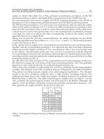
Figure 3.6 illustrates our last example.You can see how two pulleys and a belt
may solve the problem of transferring power to a distant axle through a narrow
space. In this particular example, the motor does not need to be locked with a
vertical beam because the torque on its shaft won’t ever reach high values (belt
slippage prevents this from happening).At the same time, the belt works like a
rubber band, too, keeping the motor from coming off its foundation.
Wiring Motors
The LEGO wiring system is so easy to use you won’t require any training.The
cables end with 2 x 2 x 2/3 connectors that attach as easily as standard bricks and
don’t need any special knowledge to be used.
As we already explained, LEGO motors are DC motors, therefore they are
sensitive to the polarity you connect them with, meaning it determines whether
the motor turns clockwise or counterclockwise. Usually, you don’t have to worry
about this, since you can control this property from your program. However, the
design of the LEGO connectors is very clever and not only prevents you from
www.syngress.com
Figure 3.6 Belts Don’t Require Very Solid Mountings
174_LEGO_03 10/25/01 3:12 PM Page 49
50 Chapter 3 • Controlling Motors
involuntarily short-circuiting the motor or the battery, but they also allow you to
reverse the polarity by simply turning them 180 degrees.
How can you test your motors without adjusting programming? There are
many different ways, as in the following:
■
RCX console Press the View button until you select the port your
motor is wired to.When the cursor (a small arrow) points to the proper
port, don’t release the button. Keeping the View button pressed, you can
press Prgm or Run to power the motor in the desired direction.
■
Software Browsing the Internet you can find and download many
good freeware programs that allow full direct control of your RCX via
your PC.They make running a motor as easy as a click of the mouse
(see Appendix A for links and resources).
■
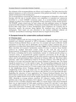
External battery box Some LEGO TECHNIC sets include a battery
box (Figure 3.7). If you want an extra motor and buy an 8735 TECHNIC
Motor set, you’ll get one.With this box you can test your motor with no
need of the RCX.
■
Remote control This useful tool is not included in the MIND-
STORMS kit, you have to buy it separately (Figure 3.8). It’s currently
sold inside the Ultimate Accessory Set that also contains additional parts.
If you can afford it, it’s a good buy.You can control all three output ports
at the same time, which is very useful when testing your robot during
the building phase.
■
Other sources All the components of the LEGO 9V electric system are
compatible with each other. If you have a LEGO train speed regulator, or
www.syngress.com
Figure 3.7 The LEGO Battery Box
174_LEGO_03 10/25/01 3:12 PM Page 50
Controlling Motors • Chapter 3 51
a Control Center unit, you can safely use them to run your motors. Don’t
use non-LEGO electricity sources.They might harm your motors.
In some cases, you want to control more than a single motor from the same
RCX output port. Is this safe for your RCX and your motors? Yes, and with no
risk of damaging either item.The only thing to point out is that the RCX has a
current-limiting device behind each port that prevents your motor from drawing
too much current to avoid any possible damage during stall situations.When you
connect two or more motors to the same port, they must share the maximum
available current, thus limiting the work they can perform. Nevertheless, there are
situations where splitting the load on two or more motors is the preferable option.
There is another possible approach that bypasses the current-limiting circuit:
indirect control. Instead of supplying the motors from your RCX port, you control a
motor that activates a switch that turns on the other motors.This sounds compli-
cated, but it isn’t.You just need some extra parts: a polarity switch and a battery
box. In Figure 3.9, you see a system devised to drive the LEGO polarity switch
with a motor and two pulleys.The belt coupling makes the system less critical
about timing. If you accidentally power the controlling motor for longer than
what’s needed to activate the switch, the belt slips and your motor doesn’t stall.
The polarity switch is actually a three-state switch: forward, off, and reverse.At
one side, it switches the motors on, in the center it switches them off, while on
the other side it switches them on again but with reversed polarity. Our simple
assembly can control only two states (don’t rely on timing to position the polarity
switch precisely in the center!), so you have to choose whether you want an
on/off system or a forward/reverse one.
As the battery box does not feature any current limiting device, your motors
can draw as much current as they need out of the batteries. Remember that with
www.syngress.com
Figure 3.8 The LEGO MINDSTORMS Kit Remote Control
174_LEGO_03 10/25/01 3:12 PM Page 51
52 Chapter 3 • Controlling Motors
this wiring the controlled motors are not protected against overloads, thus stall
situations might permanently damage them.
Controlling Power
You know that your program can control the power of your motors. In fact, a
specific instruction will set the power level in the range 0 to 7 (some alternative
firmware, like legOS, provide higher granularity, e.g., 0 to 255). But what happens
when you change this number? And why do we care?
There are different ways to control the power of an electric motor.The
LEGO train speed regulator controls power through voltage: the higher the
voltage, the higher the power.The RCX uses a different approach, called pulse
width modulation (PWM).
To explain how this works, imagine that you continuously and rapidly switch
your motor on and off.The power your motor produces in any given interval
depends on how long it’s been on in that period. Applying current for a short
period of time (a low duty cycle) will do less work than applying it for a longer
time. If you could switch it on and off hundreds of times a second, you would see
the motor turning in an apparently normal way; but under load you would notice
a decrease in its speed, due to a decrease in the supplied power (Figure 3.10).
This is exactly what the RCX does. Its internal motor controller can switch
the power on and off very quickly (an on/off cycle every 8 milliseconds), at the
same time varying the proportion between the on period and the off period.At
power level 0, the motor is on for 1/8 of the cycle; at power level 1, for 2/8 of it;
and so on until you reach level 7, when the motor is always on (8/8).
www.syngress.com
Figure 3.9 Indirect Motor Control
174_LEGO_03 10/25/01 3:12 PM Page 52
Controlling Motors • Chapter 3 53
Why do we care about this technical stuff? Because this explains you aren’t
actually controlling speed, but power. LEGO motors are very efficient, and when
the motor has no load or a very small one, lowering the power level won’t
decrease its speed very much. Under more load, you will see how the power level
affects the resulting speed, too.
Braking the Motor
Controlling the power means also being able to brake your motor when neces-
sary. For this purpose, the RCX features a sort of electric brake. Once again, let
us explain how it works through an experiment.
You need a motor, a cable (any length), and a 24t gear.Assemble the three as
shown in Figure 3.11, paying attention to the way the cable is looped: the ends of
the wire go on opposite sides. Now try and turn the 24t with your fingers: it
turns smoothly, and continues to spin for a while after you’ve stopped turning it.
Then remove the cable and reconnect it as shown in Figure 3.12: the ends of
the wire go into the same side—this way the motor is short-circuited.We know
that a short circuit sounds like a bad thing, but in this particular case we mean only
that the circuit is closed. Don’t worry, your motor is not at any risk. Now try and
turn the 24t again.You see? The motor offers a lot of resistance, and as soon as
you stop turning, it stops, too.
What happened? A LEGO motor is not only able to transform electricity
into motion, it does the opposite, too: It can be used to generate electricity. In our
experiment the generated current short-circuits back into the motor, producing
www.syngress.com
Figure 3.10 Pulse Width Modulation Power Levels
174_LEGO_03 10/25/01 3:12 PM Page 53
54 Chapter 3 • Controlling Motors
the force that resists the motion.This is the simple but effective system the RCX
implements to brake the motor:When you set them to off, the RCX not only
switches the power off, it also short-circuits the port, making the motor brake.
There’s another condition, called float mode, where the RCX simply discon-
nects the motor without creating any brake effect. In this case, the motor will
continue to turn for a few seconds after the power has been removed.
www.syngress.com
Figure 3.11 In This Setup, the Motor Shaft Turns Smoothly
Figure 3.12 An Electric Brake
174_LEGO_03 10/25/01 3:12 PM Page 54
Controlling Motors • Chapter 3 55
Coupling Motors
We previously discussed the case in which you want to wire two motors to the
same port. If you do this to get more power for a task, you will very likely need
to mechanically couple the motors as well, meaning that they will work together
to operate the same mechanism, sharing its load. It’s like when you have to move
something really heavy and call a friend to help you: each member of the party
bears only half the total weight.Though this rule works for all electric motors in
general, a specific limitation applies when attaching LEGO motors to the RCX:
Its current-limiting device won’t allow the motors to draw as much current as
they want. Consider it a constraint to the maximum power each port can pay out.
In Figure 3.13, you see two motors acting upon the same 40t gear wheel.
People often wonder whether connections like these are going to cause any
problem to the motors.The answer is simply no. Unless you keep your motor
stalled for more than a brief moment, they are not easy to damage. In applications
like the one in Figure 3.13, you just have to be sure the motors don’t oppose
each other.With this in mind, we suggest you double-check both the connection
and turning directions before actually coupling the motors to the same gear.
It is true that no two motors turn exactly at the same speed, or output the
same torque either, but this doesn’t cause any conflict.A motor doesn’t know that
there’s another motor cooperating on the same task, it simply reacts to the load
absorbing more current and trying to keep the speed.This works even if the
motors are of different types, even if they are powered at different levels, and even
if they are geared with different ratios.
If you’re not convinced of this, think of a simple vehicle propelled by a single
motor.When the path becomes steeper, the load on the motor increases, causing
www.syngress.com
Using Motors as Generators
If you are not convinced that a motor works as a generator, too, perform
this simple experiment. Connect one motor to another with a wire. Place
a 24t on each shaft. Take one motor in your hands and turn the 24t
while looking at the second motor. What happens? The first motor con-
verts the mechanical energy coming from your fingers into electric cur-
rent, which makes the second motor turn.
Bricks & Chips…
174_LEGO_03 10/25/01 3:12 PM Page 55
56 Chapter 3 • Controlling Motors
it to reduce its speed. Essentially, the motor adapts itself to the load.The same
happens when two motors work together, they share the load and mutually adapt
themselves.
Have you ever tried riding a tandem bicycle? Your partner might be much
weaker than you, but you would prefer him to pedal rather than simply ride
along watching the landscape.
Summary
LEGO electric motors are easy and safe to use, but they require a bit of experi-
ence to get the most from them and avoid any possible damage. On this latter
topic, the most important thing is to never let them stall for more than a few sec-
onds and to never keep them powered when they’ve stalled.You already know
from Chapter 2 that the clutch gear is a good ally in this venture, and you’ve now
learned that the RCX has further protections that limit the maximum current
and thus the risk that your motor will burn out.
You’ve seen that wiring LEGO motors is very simple:The special connectors
prevent short circuits and allow easy control of polarity, which affects the direc-
tion in which a motor turns.The different mounting options require a bit of
practice, the same as for gears. Don’t forget to brace motors with vertical beams
the way you were taught in Chapter 1:They produce enough torque to pull
themselves apart if not solidly locked!
On the topic of coupling motors, this option is useful when you want to split a
load over two or more of them to reduce their individual effort.The only impor-
tant thing to remember is that you must control them from the same port, so as to
avoid any dangerous conflict situation where one motor opposes to the other.
As a general tip, we suggest you make intense use of prototyping—don’t wait
to finish your robot to discover a motor is in the wrong place or has not been
geared properly—test your mechanisms while you are building them.
www.syngress.com
Figure 3.13 Two Mechanically Coupled Motors
174_LEGO_03 10/25/01 3:12 PM Page 56
Reading Sensors
Solutions in this chapter:
■
Touch Sensor
■
Light Sensor
■
Rotation Sensor
■
Temperature Sensor
■
Sensor Tips and Tricks
■
Other Sensors
Chapter 4
57
174_LEGO_04 10/25/01 3:13 PM Page 57
58 Chapter 4 • Reading Sensors
Introduction
Motors, through gears and pulleys, provide motion to your robot; they are the
muscles that move its legs and arms.The time has come to equip your creature
with sensors, which will act as its eyes, ears, and fingers.
The MINDSTORMS box contains two types of sensors: the touch sensor (two
of them) and the light sensor. In this chapter, we’ll describe their peculiarities, and
those of the optional sensors that you can buy separately: the rotation sensor and
the temperature sensor.All these devices have been designed for a specific purpose,
but you’ll be surprised at their versatility and the wide range of situations they
can manage.We will also cover the cases where one type of sensor can emulate
another, which will help you replace those that aren’t available. Using a little trick
that takes advantage of the infrared (IR) light on the RCX, you will also discover
how to turn your light sensor into a sort of radar.
We invite you to keep your MINDSTORMS set by your side while reading
the chapter, so you can play with the real thing and replicate our experiments.
For the sake of completeness, we’ll describe some parts that come from MIND-
STORMS expansion sets or TECHNIC sets. Don’t worry if you don’t have them
now; this won’t compromise your chances to build great robots.
Touch Sensor
The touch sensor (Figure 4.1) is probably the simplest and most intuitive member
of the LEGO sensor family. It works more or less like the push button portion of
your doorbell: when you press it, a circuit is completed and electricity flows
through it.The RCX is able to detect this flow, and your program can read the
state of the touch sensor, on or off.
If you have already played with your RIS, read the Constructopedia, and built
some of the models, you’re probably familiar with the sensors’ most common
www.syngress.com
Figure 4.1 The Touch Sensor
174_LEGO_04 10/25/01 3:13 PM Page 58
www.syngress.com
application, as bumpers. Bumpers are a simple way of interacting with the environ-
ment; they allow your robot to detect obstacles when it hits them, and to change
its behavior accordingly.
A bumper typically is a lightweight mobile structure that actually hits the
obstacles and transmits this impact to a touch sensor, closing it.You can invent
many types of bumpers, but their structure should reflect both the shape of your
robot as well as the shape of the obstacles it will meet in its environment.A very
simple bumper, like the one in Figure 4.2, could be perfectly okay for detecting
walls, but might not work as expected in a room with complex obstacles, like
chairs. In such cases, we suggest you proceed by experimenting. Design a tentative
bumper for your robot and move it around your room at the proper height from
the floor, checking to see if it’s able to detect all the possible collisions. If your
bumper has a large structure, don’t take it for granted that it will impact the
obstacle in its optimal position to press the sensor. Our example in Figure 4.2 is
actually a bad bumper, because when contact occurs, it hardly closes the touch
sensors at the very end of the traverse axle. It’s also a bad bumper because it trans-
mits the entire force of the collision straight to the switch, meaning an extremely
solid bracing would be necessary to keep the sensor mounted on the robot.
Be empirical, try different possible collisions to see if your bumper works
properly in any situation.You can write a very short program that loops forever,
producing a beep when the sensor closes, and use it to test your bumper.
When talking of bumpers, people tend to think they should press the switch
when an obstacle gets hit. But this is not necessarily true.They could also release
the switch during a collision. Look at Figure 4.3, the rubber bands keep the
Reading Sensors • Chapter 4 59
Figure 4.2 A Simple Bumper
174_LEGO_04 10/25/01 3:13 PM Page 59
60 Chapter 4 • Reading Sensors
bumper gently pressed against the sensor; when the front part of the bumper
touches something, the switch gets released.
Actually, there are some important reasons to prefer this kind of bumper:
■
The impact force doesn’t transfer to the sensors itself. Sensors are a bit
more delicate than standard LEGO bricks and you should avoid
shocking them unnecessarily.
■
The rubber bands absorbing the force of the impact preserve not only
your sensor but the whole body of your robot.This is especially impor-
tant when your robot is very fast, very heavy, very slow in reacting, or
possesses a combination of these factors.
Bumpers are a very important topic, but touch sensors have an incredible
range of other applications.You can use them like buttons to be pushed manually
when you want to inform your RCX of a particular event. Can you think of a
possible case? Actually, there are many. For example, you could push a button to
order your RCX to “read the value of the light sensor now,” and thus calibrate
readings (we will discuss this topic later). Or you could use two buttons to give
feedback to a learning robot about its behavior, good or bad.The list could be long.
Another very common task you’ll demand from your switch sensors is position
control.You see an example of this in Figure 4.4.The rotating head of our robot
www.syngress.com
Figure 4.3 A Normally Closed Bumper
174_LEGO_04 10/25/01 3:13 PM Page 60
Reading Sensors • Chapter 4 61
(Figure 4.4a) mounts a switch sensor that closes when the head looks straight
ahead (Figure 4.4b).Your software can rely on timing to rotate the head at some
level (right or left), but it can always drive back the head precisely in the center
simply waiting for the sensor to close. By the way, the cam piece we used in this
example is really useful when working with touch sensors, as its three half-spaced
crossed holes allow you to set the proper distance to close the sensor.
There would be many other possible applications in regards to position control.
We’ll meet some of them in the third part of this book.What matters here is to
invite you to explore many different approaches before actually building your
www.syngress.com
Figure 4.4 Position Control with a Touch Sensor
174_LEGO_04 10/25/01 3:13 PM Page 61
62 Chapter 4 • Reading Sensors
robot. Let’s create another example to clarify what we mean. Suppose you’re going
to build an elevator.You obviously want your elevator to stop at any floor.Your first
idea is to put a switch at every level, so when one of them closes you know that
the cab has reached that level. Okay, nice approach.There’s one small problem;
however, you have just two touch sensors, and an elevator with only two floors
doesn’t seem like such an interesting project to you.You could buy a third sensor,
but this simply pushes your problem one floor up, without solving the general case.
Meanwhile, the three input ports of your RCX are all engaged. Suddenly, an idea
occurs to you:Why not put the sensor on the booth instead of on the structure?
With a single sensor on the booth, and pegs that close it at any floor, you can pro-
vide your elevator with as many floors as you like.You see, by reversing our original
approach you found a much better solution.Are the two systems absolutely equiva-
lent? No, they aren’t. In the first, you could determine the absolute position of the
booth, while in the second you are able to know only its relative position.That is,
you do need a known starting point, so you can deduce the position of the cab
counting the floors from there. Either require that the cab must be at a specific
level when the program starts, or use a second sensor to detect a specific floor. For
example, place a sensor at the ground level, so the very first thing your program has
to do when started is to lower the elevator until it detects the ground level. From
then on, it can rely on the cab sensor to detect its position.
Now your elevator is able to properly navigate up and down.You have one
last problem to solve: How do you inform your elevator which floor it should go
to? Placing a touch sensor at every floor to call the elevator there is impractical.
You have only one input port left on your RCX.What could you do with a
single sensor? Can you apply the previous approach here, too?
Yes.You can count the pushes on a single touch sensor. For example, three clicks
means third floor, and so on. Now you are ready to actually build your elevator!
www.syngress.com
Counting Clicks
The following examples are written using a pseudo-code—that is, a code
that does not correspond to any real programming language, but rather
lies between a programming language and natural language. Using
pseudo-code is a common practice among professional programmers;
Bricks & Chips…
Continued
174_LEGO_04 10/25/01 3:13 PM Page 62
Reading Sensors • Chapter 4 63
www.syngress.com
you are “playing computer” and quickly stepping through an operation
in your head to plan and understand what your program will do.
Counting how many times a touch sensor is pressed requires some
tricks. Suppose you write some simple code, like this:
Counter = 0
repeat
if Sensor1 is on then
Counter = Counter+1
end if
end repeat
Your code executes so fast on your RCX that during the short
instant you keep the touch sensor pressed, it counts too many clicks.
Thus, you need to have it wait for the button to be released before
counting a new click:
Counter = 0
repeat
if Sensor1 is on then
Counter = Counter+1
wait until Sensor1 is off
end if
end repeat
Now, your code counts properly the transitions from off to on.
There’s one last feature you must introduce in your code: You want the
counting procedure to end when it doesn’t receive a click for a while. To
do this, you employ a timer that measures the elapsed time from the last
click:
Counter = 0
Interval = <a proper value>
reset Timer
repeat
if Sensor1 is on then
Counter = Counter+1
wait until Sensor1 is off
Continued
174_LEGO_04 10/25/01 3:13 PM Page 63
64 Chapter 4 • Reading Sensors
Light Sensor
Saying that the light sensor (Figure 4.5) “sees” is definitely too strong a statement.
What it actually does is detect light and measure its intensity. But in spite of its
limitations, you can use it for a broad range of applications.
The most important difference between the touch sensor and the light sensor,
is that the latter returns many possible values instead of a simple on/off state.
These values depend on the intensity of the light that hits the sensor at the time
you read its value, and they are returned in the form of percentages ranging from
0 to 100.The more light, the higher the percentage.What can you do with such
a device? A possible application is to build a light-driven robot, a light follower as
it’s called, that looks around to find a strong (or the strongest) light source and
directs itself toward it. Provided that the room is dark enough not to produce
interference, you could then control your robot using a flashlight.
www.syngress.com
or until Timer is greater then Interval
reset Timer
end if
until Timer is greater then Interval
Let’s say your interval is two seconds. When the counting proce-
dure begins, it resets the timer and the counter to 0 then starts checking
the sensor. If nothing happens in two seconds, it exits the repeat group.
If a click occurs, it counts it, waits for the user to release the button, and
resets the timer so the user has again two seconds for another click
before the procedure ends.
Figure 4.5 The Light Sensor
174_LEGO_04 10/25/01 3:13 PM Page 64
Reading Sensors • Chapter 4 65
This ability to trace an external light source is interesting, but probably not
the most amazing thing you can do with this sensor.We introduce here another
feature of this device: not only does it detect light, but it emits some light as well.
There is a small red LED that provides a constant source of light, thus allowing
you to measure the reflected light that comes back to the sensor.
When you want to measure reflected light, you must be careful to avoid any
possible interference from other sources. Remember that this sensor is very sensi-
tive to IR light, too, like the one typically emitted by remote controls, video
cameras, or the LEGO IR tower.
The amount of light reflected by a surface depends on many factors, mainly
its color, texture, and its distance from the source.A black object reflects less light
than a white one, while a black matte surface reflects less light than a black shiny
surface. Plus, the greater the distance of the objects from the sensor, the less light
returns to the detector.
These factors are interdependent, meaning that with a simple reading from
your light sensor, you cannot tell anything about them. But if you keep all the
factors constant except one, you are now able to deduce many things from the
readings. For example, if your light sensor always faces the same object, or objects
with the same texture and color, you can use it to measure its relative distance.On
the other hand, you can place different objects in front of the sensor, at a constant
distance, to recognize their color (or, more accurately, their reflection).
www.syngress.com
Reading Ambient Light
The LEGO light sensor is actually not a great device to measure external
sources, as its sensitivity is too low. The emitting red LED is so close to
the detector that it strongly influences the readings. If your target is an
external source, you might consider trying to reduce the effect of the
emitting LED. A simple solution is to place a 1 x 2 one-hole brick just in
front of the light sensor. Much more effective solutions require that you
slightly modify your sensor. On his Web site, Ralph Hempel shows how
to make modifications that neither permanently alter nor damage your
sensor (see Appendix A).
Designing & Planning…
174_LEGO_04 10/25/01 3:13 PM Page 65
66 Chapter 4 • Reading Sensors
Measuring Reflected Light
To illustrate the concept of measuring reflected light, let’s prepare an experiment.
Take your RCX, turn it on, attach a light sensor to any input port, and configure
the port properly using the Test Panel of your MINDSTORMS box (the red
LED should illuminate). Prepare the environment.You need a dark room, not
necessarily completely dark but there should be as little light as possible.The
RCX has a console mode that allows you to view the value of a sensor in real
time. Press the View button on your RCX until a short arrow in the display
points to the port the sensor is attached to.The main section of the display shows
the value your sensor is reading. Now you can proceed. Put the light sensor on
the table.Take some LEGO bricks of different colors and place them one by one
at short distances from the sensor (about 0.5 in., or 1 to 1.5 cm). Keep all of
them separated from each other at the same distance, and look at the readings.
You will notice how different colors reflect a different amount of light (you
might want to write down the values on a sheet).
For the second part of the experiment, take the white brick and move it
slowly toward the sensor and then away from it, always looking at the values in
the display.You see how the values decrease when you increase the distance.You
can find a distance where the white brick reads the same value you have read for
the black one at a shorter distance.This is what we meant to prove:You cannot
tell the distance and the color at the same time, but if you know that one of the
properties doesn’t change, you can calculate the other.We stress again that in both
cases you must do your best to shield your system from ambient light.
www.syngress.com
Understanding Raw Values
Understanding raw values is an advanced topic, and not strictly neces-
sary to successfully using the MINDSTORMS system. That said, it does
help to understand how to work with sensors.
The RCX converts the electrical signals coming from sensors (of any
type) into whole numbers in the range of 0 to 1023, called raw values.
When, in your program, you configure a port to host a specific kind of
sensor, the RCX automatically scales raw values to a different range,
Bricks & Chips…
Continued
174_LEGO_04 10/25/01 3:13 PM Page 66
Reading Sensors • Chapter 4 67
Reading colors is a very common application for light sensors.We already
explained that the sensor doesn’t actually read colors, rather it reads the reflected
light. For this reason, it’s hard to tell a black brick from a blue one. But, for now,
let’s continue to use the expression reading colors, now that you know what’s really
behind the reading.
Line Following
Probably the most widespread usage of the light sensor is to make the robot read
lines or marks on the floor where it moves.This is a way to provide artificial
www.syngress.com
suitable for that particular kind of sensor. For example, readings from
touch sensors become a simple 1 or 0 digit, meaning on or off, while
readings from a temperature sensor convert into Celsius or Fahrenheit
degrees. Similarly, light sensor readings are converted into percentages
through use of the following equation:
Percentage = 146 - raw value / 7
Why should you need to know about this conversion? Well, for
most applications the percentage light value returned by the RCX works
well, but there are situations where you need all the possible resolution
your sensor can provide, and this conversion into percentages masks
some of the resolution your light sensor is capable of. Let’s explain this
with an example. Suppose that, in two different conditions, your light
sensor returns raw values of 707 and 713. Convert these numbers into
percentages, considering that RCX uses whole numbers only, and thus
rounds the result of a division to the previous integer:
146 - (707 / 7) = 146 - 101 = 45
146 - (713 / 7) = 146 - 101 = 45
The 101 in the second equation should have been 101.857…, but
it’s been truncated to 101, and you lost the difference between the two
readings. We agree that in most situations this granularity of readings is
not very important, but there are others where even such a small interval
matters.
If you program your RCX using RCX Code, the graphic LEGO envi-
ronment, you must accept the scaled values, because you have no way
to access raw values. But if you use alternative programming tools you
can choose to receive the unprocessed raw values directly, taking advan-
tage, when necessary, of their finer resolution.
174_LEGO_04 10/25/01 3:13 PM Page 67
68 Chapter 4 • Reading Sensors
landmarks your robot can rely on to navigate its environment.The simplest case
is line following.The setup for this project is very simple, which is one of the rea-
sons it’s so popular. Despite its apparent simplicity, this task deserves a lot of
attention and requires careful design and programming.We will discuss this topic
in greater detail in Part II; for now, though, we want to bring your attention to
what happens when the light sensor “reads” a black line on a light floor.
When the sensor is on the floor, it returns, let’s say, 70 percent, while on the
black line, it returns 30 percent. If you move it slowly from the floor to the line
or vice versa, you notice that the readings don’t leap all of a sudden from one to
the other, they go through a series of intermediate values.This happens because
the sensor doesn’t read a single point, but a small area in front of it. So when the
sensor is exactly over the borderline, it reads half the floor and half the black
strip, returning an intermediate result.
Is this feature useful? Well, sometimes it is, sometimes it’s not.When dealing
with line following in particular, it is very useful. In fact, you can (and should)
program your robot to follow the “gray” area along the borderline rather than the
actual black line.This way when the robot needs to correct its course, it knows
which direction to turn: If it reads too “dark,” it should turn toward the “light”
region, and vice versa.
www.syngress.com
Calibrating Readings
Sometimes you can’t know in advance what actual values your sensor is
going to read. Suppose you’re going to attend a line following contest:
You cannot be sure of the values your sensor will return for the floor and
the black line. In this case, and as a good general practice, it is better
not to write the expected values as constants in your program, but allow
your robot to read them by itself through a simple calibration proce-
dure. Staying with the line following example, you can dedicate a free
input port to a touch sensor to be manually pressed when you put your
robot on the floor and then on the black line, so it can store the max-
imum and minimum readings. Or you can program the robot to perform
a short exploration tour to uncover those limits itself.
Designing & Planning…
174_LEGO_04 10/25/01 3:13 PM Page 68
Reading Sensors • Chapter 4 69
When you need to navigate a more complex area, one, for example, that
includes regions of three different colors, things get more difficult. Imagine a pad
divided into three fields: white, black, and gray. How can you tell the gray area
from the borderline between the white and the black? You can’t, not from a
single reading, anyway.You must take into consideration other factors, like pre-
vious readings, or you can make your robot turn in place to make it gather more
information and understand where it is.To handle a situation like this, your soft-
ware is required to become much more sophisticated.
The light sensor is such a versatile device that you can imagine many other
ways to employ it.You can build a form of proportional control by placing a
multicolor movable block of LEGO parts in front of it. Figure 4.6 shows an
example of this kind.When you push or pull the upper side of the beam, the
sensor reads different light intensities.
Combining the light sensor with a lamp brick (not included in the MIND-
STORMS kit) you get a photoelectric cell (Figure 4.7); your robot can detect
when something interrupts the beam from the lamp to the sensor. Notice that
we placed a 1 x 2 one-hole beam in front of the light sensor to reduce the pos-
sible interference from ambient light.
www.syngress.com
Figure 4.6 An Analogue Control with a Light Sensor
Figure 4.7 A Photoelectric Cell
174_LEGO_04 10/25/01 3:13 PM Page 69
70 Chapter 4 • Reading Sensors
Proximity Detection
You can also use the light sensor as a sort of radar to detect obstacles before your
robot hits them.This is called proximity detection.The technique is based on a
property we have already discussed and explored: that the light sensor can be used
to measure relative distances based on reflected light. Suppose your robot is going
straight, with a light sensor pointing ahead of it. Suppose also that your robot
moves in a dark room, with no other sources of light except the emitting red
LED of the sensor.While moving forward, the robot continuously reads the
sensor. If the readings tend to increase rapidly, you can deduce that the robot is
going toward something.There’s nothing you can tell about the nature of the
obstacle and its distance, but if nothing else moves inside the room, you are sure
the robot is getting closer to the obstacle. Great! We now have a system to avoid
obstacles instead of being limited to detecting them through collisions.
NOTE
The red LED in the sensor emits visible light, while the IR LED in the RCX
emits invisible light!
Unfortunately, this technique doesn’t work very well in a room with any
source of light, because your program cannot tell the difference between its red
light reflected back, or any other change in the ambient light.You would need a
stronger independent source on the robot to provide a better reference.
Thankfully, you just happen to have one! The RCX has an IR LED to send mes-
sages to the tower or to another RCX. Sending a message uses the IR LED in
the RCX to encode the bits in a format that can be received by the tower.We
don’t care about the contents of the message; we just want the light. Infrared
light, though not visible to the human eye, is of the very same nature as visible
light, and the LEGO light sensor happens to be very sensitive to it.
So you now have all the elements to use proximity detection in your pro-
grams. Send an IR message and immediately read the light sensor.You had better
average some readings to minimize the effect of external sources (we’ll discuss
this trick in Chapter 12). If you notice a significant increase between two subse-
quent groups of readings, for example, ten percent, your robot is very likely
headed towards an obstacle.
www.syngress.com
174_LEGO_04 10/25/01 3:13 PM Page 70
Reading Sensors • Chapter 4 71
Rotation Sensor
The third LEGO sensor we’ll examine is the rotation sensor (Figure 4.8). It’s a pity
this piece of hardware is not included in the MINDSTORMS kit, its versatility
being second only to the light sensor. However, there is one included in the 3801
Ultimate Accessory Set, together with a touch sensor, a lamp brick, the remote
control, and a few other additional parts.
The rotation sensor, as its name suggests, detects rotations. Its body has a hole
that easily fits a LEGO axle.When connected to the RCX, this sensor counts a
unit for every sixteenth of a turn the axle makes.Turning in one direction, the
www.syngress.com
Figure 4.8 The Rotation Sensor
How the Rotation Sensor Works
The rotation sensor returns four possible values that correspond to four
states, let’s call them A, B, C, and D. For every complete turn, it passes
through the four states four times—that’s why we get 16 counts per
turn. Turning the sensor clockwise, it will read the sequence ABCDA ,
while turning it counterclockwise will result in the sequence ADCBA.…
The RCX polls the sensor frequently, and when it detects that the state
has changed, it can not only deduce that the sensor has turned, but also
tell in which direction it has turned. For example, transitions from A to
B, or from D to A, increment the counter by one unit, whereas transi-
tions from D to C, or from A to D, decrement it by one unit.
Bricks & Chips…
174_LEGO_04 10/25/01 3:13 PM Page 71
72 Chapter 4 • Reading Sensors
count increases, while turning in the other, the count decreases.This count is rela-
tive to the starting position of the sensor.When you initialize the sensor, its count
is set to zero, and you can reset it again in the code, if necessary.
By counting rotations, you can easily measure position and speed.When con-
nected to the wheels of your robot (or to some gearing that moves them), you
can deduce the traveled distance from the number of turns and the circumference
of the wheel.Then you can convert the distance into speed, if you want, dividing
it by the elapsed time. In fact, the basic equation for distance is:
distance = speed x time
from which you get:
speed = distance / time
If you connect the rotation sensor to any axle between the motor and the
wheel, you must remember to apply the proper ratio to the count you read. Let’s
do an example along with the math together. In your robot, the motor is con-
nected to the main wheels with a 1:3 ratio.The rotation sensor is directly con-
nected to the motor, so it shares the same 1:3 ratio with the wheel, meaning that
every three turns of the rotation sensor, the wheels make one turn. Every rotation
of the sensor counts 16 units, so 16 x 3 = 48 increments, which correspond to a
single turn of the wheel. Now, to calculate the traveled distance we need to know
the circumference of the wheel. Luckily, most of the LEGO wheels have their
diameter marked on the tire.We had chosen the largest spoked wheel, which is
81.6cm in diameter (LEGO uses the metric system), thus its circumference is
81.6 x π≈81.6 x 3.14 = 256.22cm.At this point, you have all the elements: the
distance traveled by the wheel results from the increment in the rotation counter
divided by 48 and then multiplied by 256. Let’s summarize the steps. Calling R
the resolution of the rotation sensor (the counts per turn) and G, the gear ratio
between it and the wheel, we define I as the increment in the rotation count that
corresponds to a turn of the wheel:
I = G x R
In our example G is 3, while R is always 16 for LEGO rotation sensors.Thus,
we get:
I = 3 x 16 = 48
On each turn, the wheel covers a distance equal to its circumference, C.You
can obtain this from its diameter D by using the formula:
www.syngress.com
174_LEGO_04 10/25/01 3:13 PM Page 72