McGraw.Hill PIC Robotics A Beginners Guide to Robotics Projects Using the PIC Micro eBook-LiB Part 4 ppt
Bạn đang xem bản rút gọn của tài liệu. Xem và tải ngay bản đầy đủ của tài liệu tại đây (1.9 MB, 20 trang )
Using DOS to Code, Compile, and Program 47
Figure 5.13 Select wink.hex in Open File message box and hit the OK button.
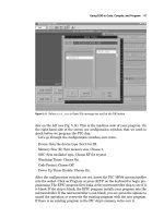
dow on the left (see Fig. 5.14). This is the machine code of your program. On
the right-hand side of the screen are configuration switches that we need to
check before we program the PIC chip.
Let’s go through the configuration switches once more.
Device: Sets the device type. Set it for 8X.
Memory Size (K): Sets memory size. Choose 1.
OSC: Sets oscillator type. Choose XT for crystal.
Watchdog Timer: Choose On.
Code Protect: Choose Off.
Power Up Timer Enable:
Choose On.
After the configuration switches are set,
insert the PIC 16F84 microcontroller
into the socket. Click on Program or press ALT-P on the keyboard to begin pro-
gramming
. The EPIC program first looks at the microcontroller chip to see if it
is blank.
If the chip is blank,
the EPIC program installs your program into the
microcontroller. If the microcontroller is not blank, you are given the options to
cancel the operation or overwrite the existing program with the new program.
If there is an existing program in the PIC chip’s memory
,
write over it.
48 Chapter Five
Figure 5.14 Hexadecimal numbers showing in EPIC window are the machine language version of
the wink.bas program that is uploaded (programmed) into the 16F84 microcontroller.
I have noticed that when I place a brand new PICmicro 16F84 chip into the
EPIC compiler to program, EPIC always reports existing code on the chip. I
don’t know if Microchip Technology Inc. loads numbers into the chip’s memory
for testing purposes. Don’t let it throw you—the PICmicro chip is new.
The machine language code lines are highlighted as the EPIC software
uploads the program into the PICmicro chip. When it is finished, the micro-
controller is programmed and ready to run. You can verify the program if you
like by hitting (or highlighting) the Verify button. This initiates a comparison
of the program held in memory to the program stored in the PIC microcon-
troller.
Chapter
6
Testing the PIC Microcontroller
The PIC Microcontroller
This is where we will build the testing circuit for the PICmicro chip we pro-
grammed. The components needed for the circuit were listed in Chap. 1; if you
purchased the components, you can quickly set up the test circuit. If not, the
components are listed again at the end of this chapter; you will need the com-
ponents to build the circuit.
The solderless breadboard
For those of us who have not dabbled in electronics very much, I want to
describe the solderless breadboard (see Fig. 6.1) in detail. As the name implies,
you can breadboard (assemble and connect) electronic components onto it
without solder. The breadboard is reusable; you can change, modify, or remove
circuitry components from the breadboard at any time. This makes it easy to
correct any wiring errors. The solderless breadboard is an important item for
constructing and testing circuits outlined in this book.
The style of breadboard on the left is available from any number of sources
including RadioShack. The breadboard on the right is similar but provides a
larger prototyping area.
If you wish to make any circuit permanent, you can transfer the components
onto a standard printed-circuit board and solder it together with the fore-
knowledge that the circuit functions properly.
A partial cutaway of the top surface shows some of the internal structure of
a board (Fig. 6.2). The holes on the board are plugs. When a wire or pin is
inserted into the hole
,
it makes intimate contact with the metal connector strip
inside. The holes are properly distanced so that integrated circuits and many
other components can be plugged in. You connect components on the board by
Copyright © 2004 The McGraw-Hill Companies. Click here for terms of use.
49
50 Chapter Six
Figure 6.1 Top view of solderless breadboards.
Figure 6.2 Top view of solderless breadboards with a partial cutaway showing underneath conductive contact strips.
using 22-gauge (solid or stranded) wire. I prefer to use stranded wire because
it has greater flexibility; other people prefer solid wire because it’s stiffer and
easier to push into the breadboard hole.
The complete internal wiring structure of the solderless boards is shown in
Fig. 6.3. The solderless breadboard on the left shows the X and Y rows that are
typically used to supply power (Vcc) and ground connections to the circuit. The
columns below the X row and above the Y row are used for mounting compo-
nents. The solderless breadboard on the right has double rows located at the
top and bottom. These are used to supply both Vcc and ground on each side of
the breadboard.
Three schematics, one circuit
Figures 6.4, 6.5, and 6.6 are identical schematics of our test circuit. The 16F84
PIC microcontroller in the schematic is the microcontroller you programmed
in either Chap. 4 or 5. I drew three schematics to help orient experimenters
who may not be familiar with standard electrical drawings. Figure 6.4 shows
Testing the PIC Microcontroller 51
Figure 6.3 Top view of solderless breadboards detailing conductive strips.
+
Electrical Symbol
Component
Appearance
4.0
MHz
470 470
4.7kΩ
+5V
1
2
3
4
5
6
7
8
9
18
17
16
15
14
13
12
11
10
RA2 RA1
RA0
OSC1/CLKIN
OSC2/CLKOUT
Vdd
RB7
RB6
RB5
RB4
RA3
RA4IT0CKI
MCLR
RB0/INT
RB1
RB2
RB3
Vss
PIC16F84
22pF
22pF
4MHz
.1uF
Xtal LED Resistor Capacitor
All resistors
1
/
4
watt
++
Figure 6.4 Isometric schematic of test circuit for wink.bas program.
how the PIC 16F84 microcontroller and components appear. There is a legend
at the bottom that shows the electrical symbol and the typical appearance of
the component. Figure 6.5 is a line drawing showing how the components
appear mounted on one of the solderless breadboards. The writing on Fig. 6.5
points out each electrical component.
52 Chapter Six
A
B
C
D
E
F
G
H
I
J
Y
X
1
1
5
5
10
10
15
15
20
20
PIC16F84
7805
Volt
Reg.
Xtal
22 pF
LEDs
Red
LED
Side
View
+
+
+
470Ω
Ground
Ground
4.7kΩ
+Vcc
Gnd
.1uF
Figure 6.5 Isometric drawing showing test circuit constructed on solderless breadboard.
Figure 6.6 Schematic of test circuit for wink.bas program.
If you examine the placement of the components mounted on the solderless
breadboard with its internal electrical wiring (F
igs
. 6.2 and 6.3), you can see
how the components connect to one another and produce a circuit.
Figure 6.6 is the same schematic drawn as a standard electrical drawing
with the pin numbers grouped and oriented to function.
F
or the remainder of
the book,
standard electrical drawings will be used.
The schematic shows how minimal are the components needed to get your
microcontroller up and running
.
Primarily you need a pull-up resistor on pin
Testing the PIC Microcontroller 53
Figure 6.7 Photograph of wink.bas circuit constructed on solderless breadboard.
4 (MCLR), a 4-MHz crystal with two (22-pF) capacitors and a 5-V power sup-
ply. Note: The 4-MHz crystal and two (22-pF) capacitors make up an oscillator
that is required by the microcontroller. These three parts may be substituted
with a 4-MHz ceramic resonator.
The two LEDs and the two resistors connected in series with each LED are
the output. It allows us to see that the microcontroller and program are func-
tioning properly.
Assemble the components as shown in the schematic (Fig. 6.5) onto the sol-
derless breadboard. When you have finished, your work should appear as in
Fig. 6.7.
Although the specifications sheet on the 16F84 states the microcontroller
will operate on voltages from 2 to 6
V,
I provided a regulated 5-V power supply
for the circuit. The regulated power supply consists of a 7805 voltage regula-
tor and two filter capacitors.
Wink
Apply power to the circuit. The LEDs connected to the chip will alternately
turn on and off
.
Wink,
…, wink. Now you know how easy it is to program these
microcontrollers and get them up and running.
54 Chapter Six
Troubleshooting the circuit
There is not too much that can go wrong here. If the LEDs do not light, the
first thing to check is the orientation of the LEDs. If they are put in backward,
they will not light.
Next check your ground wires. See the jumper wires on the right-hand side
of the solderless breadboard. They bring the ground up to the two 22-pF capac-
itors.
Check all your connections. Look back at Figs. 6.2 and 6.3 to see how the
underlying conductive strips relate to the push in terminals on top of the
board.
PIC Experimenter’s Board and LCD Display
There are two optional tools you may want if you plan on experimenting with
the PIC16F84 and microcontrollers in general. They are the PIC
Experimenter’s Board and LCD display. We will look at the LCD display first
because a similar LCD display is incorporated into the PIC Experimenter’s
Board and what we say about the stand-alone LCD display is also true for the
PIC Experimenter’s Board LCD display.
One thing PIC microcontrollers lack is some type of display. With a display,
the chip could show us how a program is running or what it is detecting. In
addition a display would allow the microcontroller to output textual and
numeric messages to the user.
To this end there are serial LCD displays on the market that only require a
single microcontroller’s I/O lines (pin) and a circuit ground. The particular
LCD display we are using receives standard serial data (RS-232) at 300, 1200,
2400, and 9600 baud (Bd) (inverted or true). The LCD module is a two-line, 16-
character visible display. The full display is actually two lines by 40 characters,
but the additional 24 characters per line are off screen. We can use the
PicBasic and PicBasic Pro
serout command to communicate and output mes-
sages to the LCD display.
The PicBasic and PicBasic Pro compilers can send and receive serial
information at 300, 1200, 2400, and 9600 Bd. Data are sent as 8 bits, no
parity, and 1 stop bit. The serial mode may be set to be true or inverted.
These data match the serial communication protocols required of the LCD
display.
The LCD module has three wires: �5
V (red), GND (black or brown), and a
serial in line (white).
The baud rate may be set to 300,
1200,
2400,
or 9600 by
using a set of jumpers (J1, J2, and J3) on the back of the LCD display.
This first program prints the message
“Hello World.” The cursor (printing
position) automatically moves from left to right.
The schematic is shown in F
ig
.
6.8,
and the LCD display is shown in F
ig
.
6.9.
‘PicBasic program
‘LCD test
pause 1000
‘Wait 1 second for LCD to initialize
Testing the PIC Microcontroller 55
PIC
Microcontroller
Ground
Serial Line
+5V
Figure 6.8 Schematic of LCD display test circuit.
Figure 6.9 Photograph of LCD display “Hello World.”
start:
serout 1, t1200, (254,1) ‘Clear screen
pause 40
serout 1, t1200, (“Hello World”) ‘Print message
pause 400
goto start
end
I kept this program small to show how easy it is to print a message on the LCD
display. Here is the same program written for the PicBasic Pro compiler.
‘PicBasic Pro program
‘LCD test
pause 1000 ‘Wait 1 second for LCD to initialize
start:
serout portb.1, 1, [254,1] ‘Clear screen
pause 40
serout portb.1, 1, [“Hello World”] ‘Print message
pause 400
goto start
end
56 Chapter Six
Notice that, in line 5 of the program(s), serout 1, t1200, (254,1) is a com-
mand. The LCD module has eight common commands. All commands are pre-
fixed with the decimal number 254. The LCD module will interpret any number
following a 254 prefix as an instruction. Instead of decimal numbers, you may
also use hexadecimal numbers, if you wish. So in hexadecimal the command
becomes
serout 1, t1200, ($fe, $01). The following is a list of a few
common commands. Remember all commands are prefixed with a 254 ($fe).
Code Instruction
1 Clear screen.
2 Home position (move cursor top left of display).
16 Move cursor one character position left.
20 Move cursor one character position right.
24 Scroll display one character position left.
28 Scroll display one character position right.
192 Move cursor to first position on second line.
PIC Experimenter’s Board
The PIC Experimenter’s Board is a prefabricated developing board for proto-
typing circuits (see Fig. 6.10). The board allows easy access to all the I/O pins,
port A (RA0–RA4), and port B (RB0–RB7) of the 16F84. The board may also be
used with the 16F8X, 16C55X, 16C62X, 16C7X, and 16C8X family of 18-pin
PIC microcontrollers.
Its 168-point solderless connection area allows for quick and easy access to
all port A (RA0–RA4) and port B (RB0–RB7) I/O lines. There is an open 18-pin
socket for inserting the microcontroller you are developing. The board includes
an integrated 16 �
2 serial LCD display (optional backlight), which can be eas-
ily connected with one wire to any I/O line (or external source).
Use
The board can be powered by either an onboard 9-V battery or an ac/dc trans-
former.
The power switch in the upper right turns power to the board on and
off. The board includes a reset button, for resetting the microcontroller. The
LCD has its own power switch, located directly above the LCD. If your LCD
has a backlight, the backlight switch is located above the LCD power switch.
I will describe the prototyping section on the PIC Experimenter’s Board, as
I did with the solderless breadboards, and finish up the description by wiring
a simple microcontroller LED project on the Experimenter’s Board. The proto-
typing is located at the lower left corner of the PIC Experimenter’s Board (see
Fig. 6.11). There is an open 18-pin socket to hold the microcontroller being
developed.
Testing the PIC Microcontroller 57
Figure 6.10 Photograph of PIC Experimenter’s prototype developing board.
The prototyping area is similar in design and function to solderless bread-
boards; see Fig. 6.12. You can breadboard (assemble and connect) electronic
components and electronic circuits into the prototyping area without solder-
ing. The prototyping area is reusable; you can change, modify, or remove cir-
cuit components at any time. This makes it easy to correct any wiring errors.
A cutaway of the prototyping area is shown in Fig. 6.13. The square holes
shown in the area are sockets. When a wire or pin is inserted into a hole, it
makes electrical contact with the underlying metal strip. The holes are spaced
so that integrated circuits and many other components can be plugged right in.
The internal electrical connection structure of the prototyping area is shown
in Fig. 6.14.
Looking at Fig. 6.15, at the top of the prototyping area we see that the
columns of bank 1 are labeled with the pin assignments from the 16F84. These
columns are directly connected to those microcontroller pins. Connecting a
wire or device to any of the three sockets in a particular column is electrically
connecting that wire or device to that I/O pin of the 16F84.
Bank 2 provides 14 individual four-socket columns. The four sockets aligned
in each individual column are electrically connected. The individual columns
are separate electrically from one another
.
Bank 3 is the same as bank 2.
58 Chapter Six
Figure 6.11 Photograph of PIC Experimenter’s Board with breadboarding area and 18-pin socket
highlighted.
Figure 6.12 Diagram of the
breadboard area.
The last row, labeled GND (ground), is electrically connected across the
entire row. There are an additional three ground sockets at the top of
bank 1.
A �5-V power is available from a four-socket column adjacent to bank 1.
Simple experiment
We shall wire a simple experiment to illustrate the use of the experimenter’s
prototyping area: blinking an LED. Yes, this is very similar to the wink pro-
Testing the PIC Microcontroller 59
Figure 6.13 Cutaway view of
breadboard area.
Figure 6.14 Underlying electrical
connections of breadboard area.
gram, with the exception that we are only using one LED this time. The fol-
lowing are a small PicBasic program and PicBasic Pro program to blink an
LED on pin RB1.
PicBasic program PicBasic Pro program
start: high 1
start: high portb.1
pause 250
pause 250
60 Chapter Six
Figure 6.15 Diagram of breadboard area with banks, ground, and
5-V power supply highlighted.
low 1 low portb.1
pause 250 pause 250
goto start goto start
The complete schematic for this experiment is shown in Fig. 6.16. Aside from
a programmed 16F84, we only need two other components: a 470-
,
1
4
-W resis-
tor and a subminiature LED. All the other components needed to make the
16F84 work are already hardwired on the PIC Experimenter’s Board.
The LED has two terminals, one longer than the other. The longer terminal
on the LED is positive, shown in the legend of Fig. 6.17. On the schematic the
LED appears as a diode. To wire this circuit, connect one lead of the
1
4
-W resis-
tor into one of the RB1 sockets. Connect the other lead of the
1
4
-W resistor into
a socket in bank 2. Take the positive lead of the LED and plug it into a socket
in the same column as the one containing the resistor lead.
Connect the oppo-
site lead of the LED, and plug it into one of the ground sockets at the bottom.
Plug the programmed 16F84 microcontroller into the 18-pin socket on the
PIC Experimenter’s board, and turn on the power. The LED should begin
blinking on for
1
4
s, then off for a
1
4
s. This on/off cycle (blinking) continually
repeats.
Built-in LCD
The onboard LCD display combines a serial interface and a 2-line by 16-char-
acter display (see Fig. 6.18). The LCD display can be set to receive serial data
at 300, 1200, or 2400 Bd (true or inverted, switch-selectable).
Testing the PIC Microcontroller 61
Figure 6.16 Schematic of blink
circuit.
Figure 6.17 Diagram of blink circuit assembled in breadboard area of
PIC Experimenter’s Board.
To use the LCD, connect a jumper from the desired output pin on the micro-
controller to the serial input. It is not necessary to connect a secondary ground
line to the serial input ground unless the serial data are coming from a source
off the Experimenter’s Board.
Like the LCD module, the onboard LCD display has two operational modes:
text and instruction.
The default is text mode;
data received via the serial
input line appears on the screen. Send the string “Images” and “Images” will
appear on the LCD. To input instructions to the LCD display, such as clear
62 Chapter Six
Figure 6.18 Photograph of PIC Experimenter’s Board with LCD controls highlighted.
screen, go to line 2, etc., you must prefix the instruction with ASCII 254
(0xFE). The byte following the prefix is seen and treated as an instruction
code. After the instruction code, the unit automatically returns to text mode.
Every instruction code must be sent with its own 254 prefix.
If your LCD is backlit, you may adjust the backlight contrast to the optimal
setting via the LCD contrast control. The contrast control is set fully clockwise
(highest contrast) at the factory, but you can adjust the control by hand.
To set the baud rate, there are three sets of jumpers: J1 to J3. Set the
jumpers in accordance with the silkscreen diagram on the Experimenter’s PC
Board. At all baud rates, serial data are received at 8 data bits, 1 stop bit, no
parity. Note that the baud rate setting is only read once at start-up, so chang-
ing the jumpers while the module is active will not have any effect on the baud
rate until the Experimenter’s Board is reset.
Once the LCD module is connected and configured to match the baud rate
of the computer/microcontroller, it will receive those transmitted data and dis-
play the information on the LCD display. For example, if you send “Hello,” then
“Hello” appears on the display. The cursor (printing position) automatically
moves from left to right.
The onboard LCD display will accept the standard LCD instructions. A par-
ticular byte is identified as an instruction when it is preceded by an instruc-
tion prefix c
haracter, ASCII 254 (0xFE hex, 11111110 binary). The onboard
LCD treats the byte immediately after the prefix as an instruction,
then auto-
matically returns to data mode. For example, the clear-screen instruction is
ASCII 1. To clear the screen, send 2541 (where the symbols mean
single bytes set to these values
, not text as typed from the keyboard). Notice
this instruction code matches the instruction code for the serial LCD display
module.
Instruction Code (decimal)
Clear screen 1
Testing the PIC Microcontroller 63
Figure 6.19 Photograph of LCD display in self-test mode.
Home position (move cursor top left of display) 2
Move cursor one character position left 16
Move cursor one character position right 20
Scroll display one character position left 24
Scroll display one character position right 28
Set cursor position (DDRAM address) 128
addr
Set point in character generator (CG) RAM 64 addr
The onboard LCD also has a self-testing mode that will print the current
baud rate as determined by the jumper settings and mode (true/inverted); see
Fig. 6.19. To enter self-test mode, connect the serial in line to ground (for true)
or 5
V (for inverted) upon LCD module start-up.
Note: If the serial input line is improperly connected for self-test mode, for
instance connected to 5 V when jumpers are set for true mode, the LCD dis-
play will remain blank. The module stays in self-test mode as long as the ser-
ial input line is held either high (inverted mode) or low (true mode). LCD
module may be exited from self-test mode on the fly by simply connecting the
serial input line to a serial source.
When you print past the end of a line, the next 24 characters do not show
up on the LCD screen. They are not lost; they are in an off-screen memory
area. All alphanumeric LCD modules have 80 bytes of memory, arranged
appropriately for a 2
40 screen. On LCDs with smaller screens (such as
this 2 16), text printed past the end of a visible line goes into memory, but
can’t be seen on the screen. Use cursor-positioning instructions to print to a
particular location on the display. Or deliberately print in off-screen memo-
ry to temporarily hide text, then send scroll-left instructions to reveal it.
Using the LCD: PicBasic and PicBasic Pro examples
Connect the serial input of the LCD to portb.0 of a PIC microcontroller. The fol-
lowing PicBasic program demonstrates sending data and commands to the LCD.
main: pause 1000 ‘Wait for the LCD to start up
serout 0, t2400, ($fe,$01) ‘Clear the screen
64 Chapter Six
pause 40
serout 0, t2400, (“Wherever you go”)
serout 0, t2400, ($fe,$c0) ‘Move to line 2
serout 0, t2400, (“there you are”)
pause 1000 ‘Wait 1 second
goto main ‘Do it again
The program clears the LCD and sends the message “Wherever you go there
you are” at 2400 Bd (true mode), waits for 2 s, and then loops indefinitely (see
Fig. 6.20). Note that in the above example, the control codes were written in
hexadecimal (base-16). Hexadecimal is specified by a dollar sign ($) prefix. If
you wish, the lines
serout 0, t2400,($fe,$01) ‘Clear the screen
serout 0, t2400,($fe,$c0) ‘Move to line 2
could also be written with decimal (base-10) notation as
serout 0, t2400,(254,1) ‘Clear the screen
serout 0, t2400,(254,192) ‘Move to line 2
Which notation you choose to use is a matter of preference. An equivalent pro-
gram can be written with PicBasic Pro as follows:
Figure 6.20 Photograph of message from pin RB0 of 16F84 microcontroller sent to onboard LCD
displa
y.
Testing the PIC Microcontroller 65
main: pause 1000 ‘Wait for the LCD to start up
serout portb.0,0,[$fe,$01] ‘Clear the screen
pause 40
serout portb.0,0,[“Wherever you go”]
serout portb.0,0,[$fe,$c0] ‘Move to line 2
serout portb.0,0,[“there you are”]
pause 1000 ‘Pause for a second
goto main ‘Loop
Introduction to Binary and the PIC Microcontroller
The term binary means “based on 2,” as in two numbers 0 and 1. It’s also like
an electric switch that has two values: on (1) and off (0).
The term bit
is an acronym that stands for the term binary digit. A bit or
binary digit can have two values, either 0 or 1. A
byte is a digital expression
(number) containing 8 bits.
Binary is important to computers and microcontrollers. The bit values of 0
and 1 are the only things a computer can read. Actually the computer or micro-
controller can’t really read, but it can sense voltage values. So a bit that is on
1 is represented by a positive voltage. Consequentially a bit 0 is off 0 and is
represented as no voltage.
A single bit by itself is of little value, but start putting them together to
make bytes (8 bits), words (16 bits, 32 bits, 64 bits, 128 bits), and so on, and we
can make the computers perform mathematics, create word processors and
spreadsheets, create a cyberspace (Internet), etc. All these applications are
based on a bit.
To read or write to a port register requires understanding a little binary.
When we read and write to any port, we use standard decimal numbers.
However it’s the binary equivalent of those decimal numbers that the PIC
microcontroller sees and uses.
The 16F84 uses 8-bit port registers so we only need to concern ourselves
with small 8-bit numbers and their decimal equivalents. Remember that an 8-
bit number is called a byte. An 8-bit number can represent any decimal value
between 0 and 255. When we write a decimal number into a register, the PIC
microcontroller can only see the binary equivalent of that decimal number
(byte) we wrote to the register
.
F
or us to understand what’s happening inside
the register, we need to be able to look at the binary equivalents of the decimal
(byte) number also. Once we can do this, our ability to effectively and elegant-
ly program the PIC microcontrollers is greatly enhanced.
Examine the binary number table at the top of the next page. It shows all the
decimal and binary number equivalents for numbers 0 through 32. By using
this information,
the binary numbers from 32 to 255 can be extrapolated.
Each decimal number on the left side of the equals sign has its binary equiv-
alent on the right side. So where we see a decimal number, the microcontroller
will see the same number as a series of 8 bits
(there are 8 bits to a byte).
66 Chapter Six
Binary Number Table
0 � 00000000 16 � 00010000 32 � 00100000
1 � 00000001 17 � 00010001 .
2 � 00000010 18 � 00010010 .
3 � 00000011 19 � 00010011 .
4 � 00000100 20 � 00010100 64 � 01000000
5 � 00000101
21 � 00010101 .
6 � 00000110 22 � 00010110 .
7 � 00000111 23 � 00010111 .
8 � 00001000 24 � 00011000 128 � 10000000
9 � 00001001 25 � 00011001 .
10 � 00001010 26 � 00011010 .
11 � 00001011 27 � 00011011 .
12 � 00001100 28 � 00011100 255 � 11111111
13 � 00001101 29 � 00011101
14 � 00001110 30 � 00011110
15 � 00001111 31 � 00011111
Figure 6.21 shows the relationship between a binary number and the two
PIC microcontroller registers that control port b. Notice each register has eight
open positions. This register can hold an 8-bit (1-byte) number. Let’s look at the
second binary number table below. Notice for each progression of the binary 1
to the left, the exponential power of 2 is increased by 1.
Second Binary Number Table
Bit no. Decimal Binary Bit no. Decimal Binary
Bit 0 1 � 00000001 Bit 4 16 � 00010000
Bit 1 2 � 00000010 Bit 5 32 � 00100000
Bit 2 4 � 00000100 Bit 6 64 � 01000000
Bit 3 8 � 00001000 Bit 7 128 � 10000000
These are relevant numbers, because each progression to the left identifies
another bit location and bit weight within the 8-bit byte.
For instance, suppose we wanted to write binary 1s at the RB6 and RB2
locations. To do so, we add their bit weights, in this case 64 (RB6) plus 4 (RB2),
which equals 68. The binary equivalent of decimal number 68 is 01000100. If
you push that number into the port B register, you will see that the binary 1s
are in the RB6 and RB2 positions. Remember this—it is important.
The open TRISB register shown in Fig. 6.21 may be used to examine num-
bers placed in the TRISB
.
The port B register may be used to examine num-
bers placed at the port B register
.
Notice the correlation between the register bit locations, bit weights, and