McGraw-Hill - The Robot Builder''''s Bonanza Episode 2 Part 9 pps
Bạn đang xem bản rút gọn của tài liệu. Xem và tải ngay bản đầy đủ của tài liệu tại đây (452.52 KB, 35 trang )
sound to quickly and efficiently navigate through dark caves. So accurate is their “sonar”
that bats can sense tiny insects flying a dozen or more feet away.
Similarly, robots don’t always need light-sensitive vision systems. You may want to con-
sider using an alternative system, either instead of or in addition to light-sensitive vision.
The following sections outline some affordable technologies you can easily use.
ULTRASONICS
Like a cave bat, your robot can use high-frequency sounds to navigate its surroundings.
Ultrasonic transducers are common in Polaroid instant cameras, electronic tape-measuring
devices, automotive backup alarms, and security systems. All work by sending out a high-fre-
quency burst of sound, then measuring the amount of time it takes to receive the
reflected sound.
616 ROBOTIC EYES
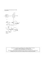
Diffraction grating
Laser
Video camera
Main beam
Sub-beams
FIGURE 37.14 When projected onto a flat surface, the beams
from the diffracted laser light form a regular
grid.
FIGURE 37.13 A penlight laser,
diffraction grat-
ing, filter, and
video camera
can be used to
create a low-
cost machine
vision system.
Ch37_McComb 8/21/00 4:26 PM Page 616
Ultrasonic systems are designed to determine distance between the transducer and an
object in front of it. More accurate versions can “map” an area to create a type of topo-
graphical image, showing the relative distances of several nearby objects along a kind of
3-D plane. Such ultrasonic systems are regularly used in the medical field. Some trans-
ducers are designed to be used in pairs—one transducer to emit a series of short ultrason-
ic bursts, another transducer to receive the sound. Other transducers, such as the kind used
on Polaroid cameras and electronic tape-measuring devices, combine the transmitter and
receiver into one unit.
An important aspect of ultrasonic imagery is that high sound frequencies disperse less
readily than do low-frequency ones. That is, the sound wave produced by a high-frequen-
cy source spreads out much less broadly than the sound wave from a low-frequency source.
This phenomenon improves the accuracy of ultrasonic systems. Both DigiKey and All
Electronics, among others, have been known to carry new and surplus ultrasonic compo-
nents suitable for robot experimenters. See Chapters 36 and 38 for more information on
using ultrasonic sensors to guide your robots.
RADAR
Radar systems work on the same basic principle as ultrasonics, but instead of high-fre-
quency sound they use a high-frequency radio wave. Most people know about the high-
powered radar equipment used in aviation, but lower-powered versions are commonly used
in security systems, automatic door openers, automotive backup alarms, and of course,
speed-measuring devices used by the police.
Radar is less commonly found on robotics systems because it costs more than ultra-
sonics. But radar has the advantage that radar it is less affected by wind, temperature, and
distance. For example, radar can be used up to several miles away; ultrasonics is useful
only up to about 10 or 20 meters.
PASSIVE INFRARED
A favorite for security systems and automatic outdoor lighting, passive pyroelectric
infrared (PIR) sensors detect the natural heat that all objects emit. This heat takes the form
of infrared radiation—a form of light that is beyond the limits of human vision. The PIR
system merely detects a rapid change in the heat reaching the sensor; such a change usu-
ally represents movement.
The typical PIR sensor is equipped with a Fresnel lens to focus infrared light from a
fairly wide area onto the pea-sized surface of the detector. In a robotics vision application,
you can replace the Fresnel lens with a telephoto lens arrangement that permits the detec-
tor to view only a small area at a time. Mounted onto a movable platform, the sensor could
detect the instantaneous variations of infrared radiation of whatever objects are in front of
the robot. See Chapter 36, “Collision Avoidance and Detection,” for more information on
the use of PIR sensors.
TACTILE FEEDBACK
Many robots can be effective navigators with little more than a switch or two to guide their
way. Each switch on the robot is a kind of “touch sensor”: when a switch is depressed, the
GOING BEYOND LIGHT-SENSITIVE VISION 617
Ch37_McComb 8/21/00 4:26 PM Page 617
robot knows it has touched some object in front of it. Based on this information, the robot
can stop and negotiate a different path to its destination.
To be useful, the robot’s touch sensors must be mounted where they will come into con-
tact with the objects in their surroundings. For example, you can mount four switches
along the bottom periphery of a square-shaped robot so contact with any object will trig-
ger one of the switches. Mechanical switches are triggered only on physical contact;
switches that use reflected infrared light or capacitance can be triggered by the proximity
of objects. Noncontact switches are useful if the robot might be damaged by running into
an object, or vice versa. See Chapter 35, “Adding the Sense of Touch,” for more informa-
tion on tactile sensors.
From Here
To learn more about… Read
Using a brain with your robot Chapter 28, “An Overview of Robot ‘Brains’”
Connecting sensors to a robot Chapter 29, “Interfacing with Computers and
computer or microcontroller Microcontrollers”
Using touch to guide your robot Chapter 35, “Adding the Sense of Touch”
Getting your robot from point Chapter 38, “Navigating through Space”
A to point B
618 ROBOTIC EYES
Ch37_McComb 8/21/00 4:26 PM Page 618
The projects and discussion in this chapter focus on navigating your robot through
space—not the outer-space kind, but the space between two chairs in your living room,
between your bedroom and the hall bathroom, or outside your home by the pool. Robots
suddenly become useful once they can master their surroundings, and being able to wend
their way through their surrounds is the first step toward that mastery.
The techniques used to provide such navigation are varied: path-track systems, infrared
beacons, ultrasonic rangers, compass bearings, dead reckoning, and more.
A Game of Goals
A helpful way to look at robot navigation is to think of it as a game, like soccer. The aim
of soccer is for the members of one team to kick the ball into a goal. That goal is guarded
by a member of the other team, so it’s not all that easy to get the ball into the goal.
Similarly, for a robot a lot stands between it and its goal of getting from one place to anoth-
er. Those obstacles include humans, chairs, cats, a puddle of water, an electrical cord—just
about anything can prevent a robot from successfully traversing a room or yard.
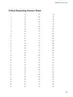
To go from point A to point B, your robot will consider the following process (as shown
in Fig. 38.1):
38
NAVIGATING THROUGH SPACE
619
Ch38_MCComb 8/29/00 8:32 AM Page 619
Copyright 2001 The McGraw-Hill Companies, Inc. Click Here for Terms of Use.
1. Retrieve instruction of goal: get to point B. This can come from an internal stimulus
(battery is getting low; must get to power recharge station) or from a programmed or
external command.
2. Determine where point B is in relation to current position (point A), and determine a
path to point B. This requires obtaining the current position using known landmarks or
references.
3. Avoid obstacles along the way. If an immovable obstacle is encountered, move around
the obstacle and recalculate the path to get to point B.
620 NAVIGATING THROUGH SPACE
Go to Point B
Locate Point B
Obstacle in way?
Move around
obstacle
No
Ye s
Read wheel
odometers
Errors in travel?
No
Ye s
Correct for
heading
Stop at point B
At point B?
Ye s
No
FIGURE 38.1 Navigation through open space requires
that the robot be programmed not only to
achieve the “goal” of a specific task but to
self-correct for possible obstacles.
Ch38_MCComb 8/29/00 8:32 AM Page 620
4. Correct for errors in navigation (“in-path error correction”) caused by such things as
wheel slippage. This can be accomplished by periodically reassessing current position
using known landmarks or references.
5. Optionally, time out (give up) if goal is not reached within a specific period of time or
distance traveled.
Notice the intervening issues that can retard or inhibit the robot from reaching its goal.
If there are any immovable obstacles in the way the robot must steer around them. This
means its predefined path to get from point A to point B must be recalculated. Position and
navigation errors are normal and are to be expected. You can reduce the effects of error by
having the robot periodically reassess its position. This can be accomplished by using a
number of referencing schemes, such as mapping, active beacons, or landmarks. More
about these later in the chapter.
People don’t like to admit failure, but a robot is just a machine and doesn’t know (or
care) that it failed to reach its intended destination. You should account for the possibility
that the robot may never get to point B. This can be accomplished by using time-outs,
which entails either determining the maximum reasonable time to accomplish the goal or,
better yet, the maximum reasonable distance that should be traveled to reach the goal.
You can build other fail-safes into the system as well, including a program override if
the robot can no longer reassess its current location using known landmarks or references.
In such a scenario, this could mean its sensors have gone kaput or that the landmarks or
references are no longer functioning or accurate. One course of action is to have the robot
shut down and wait to be bailed out by its human master.
Following a Predefined Path: Line
Tracing
Perhaps the simplest navigation system for mobile robots involves following some prede-
fined path that’s marked on the ground. The path can be a black or white line painted on a
hard-surfaced floor, a wire buried beneath a carpet, a physical track, or any of several other
methods. This type of robot navigation is used in some factories. The reflective tape
method is preferred because the track can easily be changed without ripping up the floor.
You can readily incorporate a tape-track navigation system in your robot. The line-trac-
ing feature can be the robot’s only means of semi-intelligent action, or it can be just one
part of a more sophisticated machine. You could, for example, use the tape to help guide a
robot back to its battery charger nest.
With a line-tracing robot, you place a piece of white or reflective tape on the floor. For
the best results, the floor should be hard, like wood, concrete, or linoleum, and not carpet-
ed. One or more optical sensors are placed on the robot. These sensors incorporate an
infrared LED and an infrared phototransistor. When the transistor turns on it sees the light
from the LED reflected off the tape. Obviously, the darker the floor the better because the
tape shows up against the background.
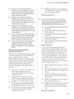
In a working robot, mount the LED and phototransistors in a suitable enclosure, as
described more fully in Chapter 36, “Collision Avoidance and Detection.” Or, use a
FOLLOWING A PREDEFINED PATH: LINE TRACING 621
Ch38_MCComb 8/29/00 8:32 AM Page 621
commercially available LED-phototransistor pair (again, see Chapter 36). Mount the
detectors on the bottom of the robot, as shown in Fig. 38.2, in which two detectors have
been placed a little farther apart than the width of the tape. I used 1/4-inch art tape in the
prototype for this book and placed the sensors 1/2 inch from one another.
Fig. 38.3 shows the basic sensor circuit and how the LED and phototransistor are wired.
Feel free to experiment with the value of R2; it determines the sensitivity of the photo-
transistor. Fig. 38.4 shows the sensor and comparator circuit that forms the basis of the
line-tracing system. Refer to this figure often because this circuit is used in many other
applications.
You can use the schematics in Fig. 38.5 and Fig. 38.6 to build a complete line-tracing
system (refer to the parts lists in Tables 38.1 and 38.2). You can build the circuit using just
three IC packages: an LM339 quad comparator, a 7486 quad Exclusive OR gate, and a
7400 quad NAND gate. Before using the robot, block the phototransistors so they don’t
receive any light. Rotate the shaft of the set-point pots until the relays kick in, then back
622 NAVIGATING THROUGH SPACE
White or reflective
strip on ground
Front view
Left
LED-Phototransistor
Right
LED-Phototransistor
FIGURE 38.2 Placement of the left and right phototransistor-LED
pair for the line-tracing robot.
LED1
Q1
+5V
R2
10K
R1
270Ω
Output
FIGURE 38.3 The basic LED-photo-
transistor wiring dia-
gram.
Ch38_MCComb 8/29/00 8:32 AM Page 622
FOLLOWING A PREDEFINED PATH: LINE TRACING 623
LED1
Q1
-
+
IC1
339 (1/4)
Output
4
5
2
+5V
+5V
R2
10K
R3
10K
R1
270Ω
R4
10K
FIGURE 38.4 Connecting the LED and phototransistor to an LM339
quad comparator IC. The output of the comparator
switches between HIGH and LOW depends on the
amount of light falling on the phototransistor. Note the
addition of the 10K “pullup” resistor on the output of the
comparator. This is needed to assure proper HIGH/LOW
action.
LED1
Q1
+5V
-
+
IC1
339 (1/4)
4
5
2
12
3
LED2
Q2
-
+
IC1
339 (1/4)
6
7
1
12
3
To Relay #2
To Relay #1
IC2
7486 (1/4)
7
14
1
2
3
1
2
3
4
5
6
R2
10K
R1
270 Ω
+5V
+5V
+5V
R4
270Ω
R5
10K
+5V
R6
10K
IC3
7400 (1/4)
14
7400 (1/4)
IC3
R3
10K
R7
10K
R8
10K
FIGURE 38.5 Wiring diagram for the line-tracing robot. The outputs of the 7400 are rout-
ed to the relays in Figure 38.6.
Ch38_MCComb 8/29/00 8:32 AM Page 623
624 NAVIGATING THROUGH SPACE
Ground
RL1
M1
D1
1N4003
+V
+5V
Ground
RL2
M2
D2
1N4003
+V
+5V
From
Detector # 1
From
Detector# 2
FIGURE 38.6 Motor direction and control relays for the line-tracing
robot. You can substitute the relays for purely electron-
ic control; refer to Chap. 18.
TABLE 38.1 PARTS LIST FOR LINE TRACER.
IC1 LM339 Quad Comparator IC
IC2 7486 Quad Exclusive OR Gate IC
IC3 7400 Quad NAND Gate IC
Q1,Q2 Infrared-sensitive phototransistors
R1,R4 270-ohm resistor
R2,R5,
R7,R8 10K resistor
R3,R6 10K potentiometer
LED1,2 Infrared light-emitting diode
Misc. Infrared filter for phototransistor (if needed)
All resistors are 5–10% tolerance.
TABLE 38.2 PARTS LIST FOR RELAY CONTROL.
RL1,RL2 DPDT fast-acting relay; contacts rated 2 amps or more
D1, D2 1N4003 diodes
Ch38_MCComb 8/29/00 8:32 AM Page 624
off again. You may have to experiment with the settings of the set point pots as you try out
the system.
Depending on which motors you use and the switching speed of the relays, you may
find your robot waddling its way down the track, overcorrecting for its errors every time.
You can help minimize this by using faster-acting relays. Another approach is to vary the
gap between the two sensors. By making it wide, the robot won’t be turning back and forth
as much to correct for small errors. I have also found that you can minimize this so-called
overshoot effect by carefully adjusting the set-point pots.
You’ll hardly ever see a railroad track with a turn tighter than about 8°. There is good
reason for this. If the turn is made any tighter, the train cars can’t stay on the track, and the
whole thing derails. There is a similar limitation in line-tracing robots. The lines cannot be
tighter than about 10° to 15°, depending on the robot’s turning radius, or the thing can’t
act fast enough when it crosses over the line. The robot will skip the line and go off course.
The actual turn radius will depend entirely on the robot. If you need your robot to turn
very tight, small corners, build it small. If your robot has a brain, whether it is a computer
or central microprocessor, you can use it instead of the direct connection to the relays for
motor control. The output of the comparators, when used with a ϩ5 volt supply, is compat-
ible with computer and microprocessor circuitry, as long as you follow the interface guide-
lines provided in Chapter 29. The two sensors require only two bits of an eight-bit port.
Wall Following
Robots that can follow walls are similar to those that can trace a line. Like the line, the wall
is used to provide the robot with navigation orientation. One benefit of wall-following
robots is that you can use them without having to paint any lines or lay down tape.
Depending on the robot’s design, the machine can even maneuver around small obstacles
(doorstops, door frame molding, radiator pipes, etc.).
VARIATIONS OF WALL FOLLOWING
Wall following can be accomplished with any of four methods:
■
Contact. The robot uses a mechanical switch, or a stiff wire that is connected to a
switch, to sense contact with the wall, as shown in Fig. 38.7a. This is by far the simplest
method, but the switch is prone to mechanical damage over time.
■
Noncontact, active sensor. The robot uses active proximity sensors, such as infrared or
ultrasonic, to determine its distance from the wall. No physical contact with the wall is
needed. In a typical noncontact system, two sensors are used to judge when the robot is
parallel to the wall (see Fig. 38.7b).
■
Noncontact, passive sensor. The robot uses passive sensors, such as linear Hall effect
switches, to judge distance from a specially prepared wall (Fig. 38.7c). In the case of
Hall effect switches, you could outfit the baseboard or wall with an electrical wire
through which a low-voltage alternating current is fed. When the robot is in the prox-
imity of the switches the sensors will pick up the induced magnetic field provided by
WALL FOLLOWING 625
Ch38_MCComb 8/29/00 8:32 AM Page 625
the alternating current. Or, if the baseboard is metal the Hall effect sensor (when rigged
with a small magnet on its opposite side) could detect proximity to a wall.
■
“Soft-contact.” The robot uses mechanical means to detect contact with the wall, but the
contact is “softened” by using pliable materials. For example, you can use a lightweight
foam wheel as a “wall roller,” as shown in Fig. 38.7d. The benefit of soft contact is that
mechanical failure is reduced or eliminated because the contact with the wall is made
through an elastic or pliable medium.
In all cases, upon encountering a wall the robot goes into a controlled program phase to
follow the wall in order to get to its destination. In a simple contact system, the robot may
back up a short moment after touching the wall, then swing in a long arc toward the wall
again. This process is repeated, and the net effect is that the robot “follows the wall.”
With the other methods, the preferred approach is for the robot to maintain proper dis-
tance from the wall. Only when proximity to the wall is lost does the robot go into a “find
wall” mode. This entails arcing the robot toward the anticipated direction of the wall. When
contact is made, the robot alters course slightly and starts a new arc. A typical pattern of
movement is shown in Fig. 38.8.
626 NAVIGATING THROUGH SPACE
Switch
Ultrasonic or
infrared
Hall effect
Roller
A
B
C
D
Wall
FIGURE 38.7 Ways to follow the wall include: a.
Contact switch; b. Noncontact active
sensor (such as infrared); c. Noncontact
passive sensor (e.g., Hall effect sensor
and magnetic, electromagnetic, or fer-
rous metal wall/baseboard); and d. “Soft
contact” using pliable material such as
foam rollers.
Ch38_MCComb 8/29/00 8:32 AM Page 626
ULTRASONIC WALL FOLLOWING
A simple ultrasonic wall follower can use two ultrasonic transmitter/receiver pairs. Each trans-
mitter and receiver is mounted several inches apart to avoid cross talk. Two transmitter/receiv-
er pairs are used to help the robot travel parallel to the wall. Suitable ultrasonic transmitter and
receiver circuits are detailed in Chapter 36, “Collision Avoidance and Detection.”
Because the robot will likely be close to the wall (within a few inches), you will want
to drive the transmitters at very low power and use only moderate amplification, if any, for
the receiver. You can drive the transmitters at very low power by reducing the voltage to
the transmitter.
WALL FOLLOWING 627
Wall
FIGURE 38.8 A wall-following robot that merely
“feels” its way around the room
might make wide, sweeping arcs.
The arc movement is easily
accomplished in a typical two-
wheeled robot by running one
motor slower than the other.
Ch38_MCComb 8/29/00 8:32 AM Page 627
SOFT-CONTACT FOLLOWING WITH FOAM WHEEL
Soft-contact wall following with a roller wheel offers you some interesting possibilities. In
fact, you may be able to substantially simplify the sensors and control electronics by plac-
ing an idler roller made of soft foam as an outrigger to the robot and then having the robot
constantly steer inward toward the wall. This can be done simply by running the inward
wheel (the wheel on the side of the wall) a little slower than the other. The foam idler roller
will prevent the robot from hitting the wall.
DEALING WITH DOORWAYS AND OBJECTS
Merely following a wall is, in essence, not that difficult. The task becomes more chal-
lenging when you want the robot to maneuver around obstacles or skip past doorways. This
requires additional sensors, perhaps whiskers or other touch sensors in the forward portion
of the robot. These are used to detect corners as well. This is especially important when
you are constructing a robot that has a simple inward-arc behavior toward following walls.
Without the ability to sense a wall straight ahead, the robot may become hopelessly trapped
in a corner.
Open doorways that lead into other rooms can be sensed using a longer-range ultrason-
ic transducer. Here, the long-range ultrasonic detects that the robot is far from any wall and
places the machine in a “go straight” mode. Ideally, the robot should time the duration of
this mode to account for the maximum distance of an open doorway. If a wall is not detect-
ed within X seconds, the robot should go into a “look for wall” mode.
Odometry: The Art of Dead Reckoning
Hop into your car. Note the reading on the odometer. Now drive straight down the road for
exactly one minute, paying no attention to the speedometer or anything else (of course,
keep your eyes on the road!). Again note the reading on the odometer. The information on
the odometer can be used to tell you where you are. Suppose it says one mile. You know
that if you turn the car around exactly 180° and travel back one mile, at whatever speed,
you’ll reach home again.
This is the essence of odometry, reading the motion of a robot’s wheels to determine
how far it’s gone. Odometry is perhaps the most common method for determining where
a robot is at any given time. It’s cheap and easy to implement and is fairly accurate over
short distances. Odometry is similar to the “dead reckoning” navigation used by sea cap-
tains and pilots before the age of satellites, radar, and other electronic schemes. Hence,
odometry is also referred to in robot literature as dead reckoning.
Unlike your car, robots don’t have speedometers connected to their transmissions
or front wheels to drive the odometer. Instead, a robot’s “odometer” is typically
devised using optical or magnetic sensors. Let’s take a look at how each kind is used in
a robot.
628 NAVIGATING THROUGH SPACE
Ch38_MCComb 8/29/00 8:32 AM Page 628
OPTICAL ENCODERS
You can use a small disc fashioned around the hub of a drive wheel, or even the shaft of a
drive motor, as an optical shaft encoder (described in “Anatomy of a Shaft Encoder,” in
Chapter 18). The disc can be either the reflectance or the slotted type:
■
With a reflectance disc, infrared light strikes the disc and is reflected back to a pho-
todetector.
■
With a slotted disc, infrared light is alternately blocked and passed and is picked up on
the other side by a photodetector.
With either method, a pulse is generated each time the photodetector senses the light.
MAGNETIC ENCODERS
You can construct a magnetic encoder using a Hall effect switch (a semiconductor sensi-
tive to magnetic fields) and one or more magnets. A pulse is generated each time a mag-
net passes by the Hall effect switch. A variation on the theme uses a metal gear and a spe-
cial Hall effect sensor that is sensitive to the variations in the magnetic influence produced
by the gear (see Fig. 38.9).
A bias magnet is placed behind the Hall effect sensor. A pulse is generated each time a
tooth of the gear passes in front of the sensor. The technique provides more pulses on each
revolution of the wheel or motor shaft, and without having to use separate magnets on the
rim of the wheel or wheel shaft.
THE FUNCTION OF ENCODERS IN ODOMETRY
As the wheel or motor shaft turns, the encoder (optical or magnetic) produces a series of
pulses relative to the distance the robot travels. Assume the wheel is 3 inches in diameter
(9.42 inches in circumference), and the encoder wheel has 32 slots. Each pulse of the
encoder represents 0.294 inches of travel (9.42/32). If the robot senses 10 pulses, it knows
it has moved 2.94 inches.
If the robot uses the traditional two-wheel drive approach, you attach optical encoders
to both wheels. This is necessary because the drive wheels of a robot are bound to turn at
ODOMETRY: THE ART OF DEAD RECKONING 629
Hall effect sensor
Ferrous metal gear
Bias magnet
FIGURE 38.9 A Hall effect sensor
outfitted with a
small “bias” mag-
net and sensitive to
the changes in
magnetic flux
caused by a rotat-
ing ferrous metal
gear.
Ch38_MCComb 8/29/00 8:32 AM Page 629
slightly different speeds over time. By integrating the results of both optical encoders, it’s
possible to determine where the robot really is as opposed to where it should be (see Fig.
38.10). As well, if one wheel rolls over a cord or other small lump, its rotation will be hin-
dered. This can cause the robot to veer off course, possibly by as much as 3° to 5° or more.
Again, the encoders will detect this change.
It’s best to make odometry measurements using a microcontroller that is outfitted with
a pulse accumulator or counter input. These kinds of inputs independently count the num-
ber of pulses received since the last time they were reset. To take an odometry reading, you
clear the accumulator or counter and then start the motors. Your software need not moni-
tor the accumulator or counter. Stop the motors, and then read the value in the accumula-
tor or counter. Multiply the number of pulses by the known distance of travel for each
pulse. (This will vary depending on the construction of your robot; consider the diameter
of the wheels and the number of pulses of the encoder per revolution.)
If the number of pulses from both encoders is the same, you can assume that the robot trav-
eled in a straight line, and you have only to multiple the number of pulses by the distance per
pulse. For example, if there are 1055 pulses in the accumulator-counter, and if each pulse rep-
resents 0.294 inches of travel, then the robot has moved 310.17 inches straight forward.
ERRORS IN ODOMETRY
In a perfect world, robots would not need anything more than an odometer to determine
exactly where they were at any given time. Unfortunately, robots live and work in a world
that is far from perfect; as a result, their odometers are far from accurate. Over a 20- to 30-
foot range, for example, it’s not uncommon for the average odometer to misrepresent the
position of the robot by as much as half a foot or more!
Why the discrepancy? First and foremost: wheels slip. As a wheel turns, it is bound to
slip, especially if the surface is hard and smooth, like a kitchen floor. Wheels slip even
630 NAVIGATING THROUGH SPACE
Obstacle under
one wheel
Actual direction
of travel
Intended direction
of travel
1000 “clicks” counted
980 “clicks” counted
FIGURE 38.10 The relative number of
“counts” from each
encoder of the typical two-
wheeled robot can be used
to indicate deviation in
travel. If an encoder shows
that one wheel turned a
fewer number of times
than the other wheel, then
it can be assumed the
robot did not travel in a
straight line.
Ch38_MCComb 8/29/00 8:32 AM Page 630
more when they turn. The wheel encoder may register a certain number of pulses, but
because of slip the actual distance of travel will be less. Certain robot drive designs are
more prone to error than others. Robots with tracks are steered using slip—lots of it. The
encoders will register pulses, but the robot will not actually be moving in proportion.
There are less subtle reasons for odometry error. If you’re even a hundredth of an inch
off when measuring the diameter of the wheel, the error will be compounded over long dis-
tances. If the robot is equipped with soft or pneumatic wheels, the weight of the robot can
deform the wheels, thereby changing their effective diameter.
Because of odometry errors, it is necessary to combine it with other navigation tech-
niques, such as active beacons, distance mapping, or landmark recognition. All three are
detailed later in this chapter.
Compass Bearings
Besides the stars, the magnetic compass has served as humankind’s principal navigation
aid over long distances. You know how it works: a needle points to the magnetic north pole
of the earth. Once you know which way is north, you can more easily reorient yourself in
your travels.
Robots can use compasses as well, and a number of electronic and electromechanical
compasses are available for use in hobby robots. One of the least expensive is the
Dinsmore 1490, from Dinsmore Instrument Co. The 1490 looks like an overfed transistor,
with 12 leads protruding from its underside. The leads are in four groups of three; each
group represents a major compass heading: north, south, east, and west. The three leads in
each group are for power, ground, and signal. A Dinsmore 1490, mounted on a circuit
board, is shown in Fig. 38.11.
The 1490 provides eight directions of heading information (N, S, E, W, SE, SW, NE,
NW) by measuring the earth’s magnetic field. It does this by using miniature Hall effect
sensors and a rotating compass needle (similar to ordinary compasses). The sensor is said
to be internally designed to respond to directional changes much like a liquid-filled com-
pass. It turns to the indicated direction from a 90° displacement in approximately 2.5 sec-
onds. The manufacturer’s specification sheet claims that the unit can operate with up to 12°
of tilt with acceptable error, but it is important to note that any tilting from center will
cause a corresponding loss in accuracy.
Fig. 38.12 shows the circuit diagram for the 1490, which uses four inputs to a comput-
er or microcontroller. Note the use of pullup resistors. With this setup, your robot can
determine its orientation with an accuracy of about 45° (less if the 1490 compass is tilted).
Dinsmore also makes an analog-output compass that exhibits better accuracy.
Another option is the Vector 2X and 2XG. These units use magneto-inductive sensors
for sensing magnetic fields. The Vector 2X/2XG provides either compass heading or
uncalibrated magnetic field data. This information is output via a three-wire serial format
and is compatible with Motorola SPI and National Semiconductor Microwire interface
standards. Position data can be provided either 2.5 or 5 times per second.
Vector claims accuracy of ±2°. The 2X is meant to be used in level applications. The
more pricey 2XG has a built-in gimbal mechanism that keeps the active magnetic-inductive
element level, even when the rest of the unit is tilted. The gimbal allows tilt up to 12°.
COMPASS BEARINGS 631
Ch38_MCComb 8/29/00 8:32 AM Page 631
632 NAVIGATING THROUGH SPACE
FIGURE 38.11 The Dinsmore 1490 digital compass provides simple bearings
for a robot. The sensor is accurate to about 45°.
1
2
3
+5 vdc
Output
10K
123
12
3
1
2
3
1
2
3
1=+V
2=Gnd
3=Output
FIGURE 38.12 Circuit diagram for using the
Dinsmore 1490 digital compass.
When used with a ϩ5 vdc supply,
the four outputs can be connected
directly to a microcontroller. One or
two outputs can be activated at a
time; if two are activated, the sensor
is reading between the four com-
pass points (e.g., N and W outputs
denotes NW position).
Ch38_MCComb 8/29/00 8:32 AM Page 632
Ultrasonic Distance Measurement
Police radar systems work by sending out a high-frequency radio beam that is reflected off
nearby objects, such as your car as you are speeding down the road. The difference
between the time when the transmit pulse is sent and when the echo is received denotes
distance. Speed is calculated using the Doppler effect: the time between the sending pulse
and echo increases or decreases proportionately depending on how fast you are going.
Radar systems are complex and expensive, and most require certification by a govern-
ment authority, such as the Federal Communications Commission for devices used in the
United States. There is another approach: you can use high-frequency sound instead to
measure distance, and with the right circuitry you can even provide a rough indication of
speed.
Ultrasonic ranging is, by now, an old science. Polaroid used it for years as an automat-
ic focusing aid on their instant cameras. Other camera manufacturers have used a similar
technique, though it is now more common to implement infrared ranging (covered later in
the chapter). The Doppler effect that is caused when something moves toward or away
from the ultrasonic unit is used in home burglar alarm systems. However, for robotics the
more typical application of ultrasonic sound is either to detect proximity to an object (see
“Ultrasonic Wall Following,” earlier in the chapter) or to measure distance (also called
ultrasonic ranging).
To measure distance, a short burst of ultrasonic sound—usually at a frequency of 40
kHz for most ultrasonic ranging systems—is sent out through a transducer (a specially
built ultrasonic speaker). The sound bounces off an object, and the echo is received by
another transducer (this one a specially built ultrasonic microphone). A circuit then com-
putes the time it took between the transmit pulse and the echo and comes up with distance.
Certainly, the popularity of ultrasonics does not detract from its usefulness in robot
design. The system presented here is suited for use with a computer or microcontroller.
There are a variety of ways to implement ultrasonic ranging. One method is to use the
ultrasonic transducer and driver board from an old Polaroid instant camera, such as the
Polaroid Sun 660 or the Polaroid SX-70 One Step. However, the driver board used in these
cameras may require some modification to allow more than one “ping” of ultrasonic sound
without having to cycle the power to the board off, then back on. More about this in a
bit.You can also purchase a new Polaroid ultrasonic transducer and driver board from a
number of mail order sources, including on the Internet. Several of these outlets are listed
in Appendix B, “Sources.” These units are new, and most come with documentation,
including hookup instructions for connecting them to popular microcontrollers, such as the
Basic Stamp. Perhaps the most common Polaroid distance measuring kit is composed of
the so-called 600 Series Instrument Grade transducer along with its associated Model 6500
Ranging Module.
The transducer, which is about the size of a silver dollar coin, acts as both ultrasonic
transmitter and receiver. Because only a single transducer is used, the Polaroid system as
described in this section cannot detect objects closer than about 1.3 feet. This is because
of the amount of time required for the transducer to stop oscillating before it sets itself up
to receive. The maximum distance of the sensor is about 35 feet when used indoors, and a
little less when used outdoors, especially on a windy day. The system is powered by a sin-
gle 6-vdc battery pack and can be interfaced to any computer or microcontroller.
ULTRASONIC DISTANCE MEASUREMENT 633
Ch38_MCComb 8/29/00 8:32 AM Page 633
FACTS AND FIGURES
First some statistics. At sea level, sound travels at a speed of about 1130 feet per second
(about 344 meters per second) or 13,560 inches per second. This time varies depending on
atmospheric conditions, including air pressure (which varies by altitude), temperature, and
humidity. The time it takes for the echo to be received is in microseconds if the object is
within a few inches or even a few feet of the robot. The short duration is really no prob-
lem, however, for fast-acting CMOS and TTL ICs. The overall time between transmit pulse
and echo is divided by two to compensate for the round-trip travel time between the robot
and the object.
Given a travel time of 13,560 inches per second for sound, it takes just 73.7 microsec-
onds (0.0000737 seconds) for sound to travel one inch. With this figure in the back of our
minds, let’s consider how the Polaroid ranging system works. The Ranging Module is con-
nected to a computer or microcontroller using only two wires: INIT (for INITiate) and
ECHO. INIT is an output, and ECHO is an input. The Ranging Module contains other I/O
connections, such as BLNK and BINH, but these are not strictly required when you are
determining distance to a single object, and so they will not be discussed here.
To trigger the Ranging Module and have it send out a burst of ultrasonic sound, the
computer or microcontroller brings the INIT line HIGH. The computer-microcontroller
then waits for the ECHO line to change from LOW to HIGH. The time difference, in
microseconds, is divided in two, and that gives you distance. To measure the time between
the INIT pulse and the return ECHO, the computer or microcontroller uses a timer to pre-
cisely count the time interval.
Different timing-counting approaches are used depending on the computer or micro-
controller you are using. For example, with the Basic Stamp or BasicX microcontrollers
(see Chapters 31 and 32, respectively), you might use the RCTime function, which is nor-
mally used to time how long it takes for a capacitor to discharge. There is no capacitor to
discharge in the Ranging Module, but the overall timing technique is still the same. With
the OOPic microcontroller (see Chapter 33), you might use its oTimer object.
Let’s suppose you’re using the BasicX microcontroller. The short bit of code in
Listing 38.1, which is taken from the BasicX application note on ultrasonic ranging, uses
pins 15 and 16 of the chip to connect to the ECHO and INIT lines, respectively, of the
Polaroid Ranging Module. The lines of the Ranging Module are connected as shown in
Fig. 38.13.
Note that the BLNK and BINH lines are held LOW and that the power supply to the
Polaroid Ranging Module must not come from the on-board regulator of the BasicX. The
Polaroid Ranging Module needs a far more robust power supply that is capable of deliver-
ing an amp or two of current for a brief period of time. Four AA batteries connected in
series will suffice. Connect the ground from the 6-vdc battery pack to the ground points
of Polaroid Ranging Module and the BasicX.
LISTING 38.1.
' Connect pin 15 of BasicX to ECHO, pin 16 to INIT
Private Const EchoPin As Byte = 15
Private Const InitPin As Byte = 16
634 NAVIGATING THROUGH SPACE
Ch38_MCComb 8/29/00 8:32 AM Page 634
' Echo delay (floating-point variable)
Dim EchoDelay As Single
' Speed of sound at room temperature (meters per second)
Const SpeedOfSound As Single = 344.0
' Take INIT HIGH and make a ping on the transducer
Call PutPin(InitPin, bxOutputHigh)
' Wait for echo to be returned
Call RCTime(EchoPin, 0, EchoDelay)
' Take INIT line LOW
Call PutPin(InitPin, bxOutputLow)
' If no echo RCTime overflows and returns 0.0
If (EchoDelay = 0.0) Then
Range = 11.0
Else
Range = (EchoDelay / 2.0) * SpeedOfSound
End If
When INIT is taken HIGH, the Polaroid Ranging Module emits a short burst of ~50
kHz sound from the transducer. The module then waits for a period of 2.38 milliseconds
for the transducer to stop ringing. This is the period of time it takes for the sonar ping to
travel about 32 inches. Considering round-trip time, this equates to the 1.3-foot minimum
imposed by the system. After this so-called “blanking” period, the Polaroid Ranging
Module listens for the return ECHO. When an echo is detected, the ECHO line goes HIGH.
Note that the module itself does not do any timing; this is the domain of the microcon-
troller that is connected to the module.
GUTTING A POLAROID SUN 660 CAMERA
Before moving on to the next subject of the chapter, it’s worth noting that used Polaroid
cameras are commonly available in thrift stores and on Internet auction sites such as eBay.
ULTRASONIC DISTANCE MEASUREMENT 635
INIT
470Ω470Ω
ECHO
BasicX
BasicX
power
Sonar
power
Sonar module
Gnd
Gnd
15
16
FIGURE 38.13 Basic sonar connec-
tion diagram for use
with the BasicX
microcontroller. Note
the separate ϩ6 vdc
power supply for the
sonar module (you
can use a 5–7 vdc
power supply that
delivers 1–2 amps
peak for a short peri-
od of time).
Ch38_MCComb 8/29/00 8:32 AM Page 635
Even models with the built-in sonar ranging system are commonly available for under $10,
and unless the camera has been damaged, they likely still work. (This is a testament to the
excellent manufacturing quality of Polaroid cameras, despite their “snap-together” con-
struction, as you’ll see in a bit.)
Most of these cameras use a transducer and ranging module very similar to the units
described already, though you will probably encounter a couple of variations. In addition,
you must first disassemble the camera to extract the ultrasonic transducer and the ranging
module board. This actually isn’t as easy as it looks, because Polaroid was known for
building their cameras with few, if any, screws. Instead, the cameras must be disassembled
like a Chinese puzzle box: first this part, then that, then this one over here—all the while
being careful you don’t break anything important.
The methods for deconstructing the typical Polaroid camera are beyond the scope of
this book, but here are a few tips. Bear in mind that when you dissect a Polaroid camera
for its ultrasonic parts you render the camera completely inoperative:
■
Start first by removing the film door and/or film rollers. This is typically accomplished
by finding and removing the small hinges and pins that hold these parts onto the main
body of the camera.
■
Pry off the faceplate. Use a thin flat-bladed screwdriver and carefully look for the
“snap” points. It’s okay if you break off a little bit of plastic here and there.
■
When you reach the innards of the camera, locate the small plastic pins that secure the
transducer element. This is a delicate part of the camera, so very carefully pry the trans-
ducer loose. Under no circumstances should you disassemble the transducer or touch
the gold-plated contact surface inside. Doing so will ruin the transducer (the gold plat-
ing will come right off in your hands).
Locate the ranging module and carefully pry it up (it’ll likely be held down with two or
more small plastic prongs). You can remove the wide multi-pin connector from the mod-
ule, but keep the shielded wires to the ultrasonic transducer intact.
When you are done, you should have something that looks like the module and trans-
ducer in Fig. 38.14. This module came out of a Sun 660, and not all Polaroid modules look
the same. Though similar in design, the pinouts of the multi-pin connector are different
from those found in the Model 6500 Ranging Module described earlier in the chapter.
Table 38.3 lists the pinouts for the Model 6500 Ranging Module as well as the ranging
module from the Sun 660. Note that the Sun 660 module has an eight-pin connector; the
Model 6500 has a nine-pin connector.
A disadvantage of using sonar ranging boards removed from Polaroid cameras is that in
many cases, the board is not able to produce more than one “ping” of ultrasonic sound with-
out recycling the power off, then back on. The Polaroid cameras from which the boards are
taken are powered by a battery contained in the film pack. Between pictures, power to the
electronics inside the camera is turned off, which resets the sonar ranging board.
There are a number of ways to modify the sonar board to permit it to ping more than once,
and without recycling its power. I’ve found that one of the most effective—and easy—meth-
ods is to add a small single-pole, single-throw (SPST) five-volt relay between the sonar rang-
ing module and the battery that powers it. The relay should be rated for at least one amp. The
relay is controlled by the robot’s microcontroller or microprocessor. A basic hook-up scheme
for controlling a relay with a computer is shown in Chapter 18, “Working with DC Motors.”
636 NAVIGATING THROUGH SPACE
Ch38_MCComb 8/29/00 8:32 AM Page 636
Infrared Distance Measurement
Ultrasonic sound is not the only method you can use to measure distance between your ‘bot
and some object. Infrared light can also be used. Unlike ultrasonic measurement, infrared
distance sensors don’t attempt to determine the time-of-flight for a light beam—it would
be on the order of femto- and picoseconds for the distances we’re interested in. Only the
most costly electronic circuitry can handle these speeds.
Instead, infrared systems use a technical known as parallax, that is, the measurement of
the angle of reflectance between a known light source and its return beam. Here’s how the
technique works: A beam of infrared light illuminates a scene. The beam reflects off an
object in front of the sensor and bounces back into the sensor. The closer the object is, the
greater the angle of displacement due to parallax. The reflected beam falls onto a linear
array of very small photodetectors. This photodetector array is connected to circuitry that
resolves the distance of the object. The circuitry can provide either a digital or an analog
output. We’ll cover both varieties here.
The premier maker of infrared distance measurement sensors for use in robotics is
Japan-based Sharp. One of their infrared distance measurement sensors, the GP2D02, is
shown in Fig. 38.15. Actually, Sharp doesn’t make these sensors for the robotics industry;
rather, they are principally intended for use in cars for proximity devices and copiers for
INFRARED DISTANCE MEASUREMENT 637
FIGURE 38.14 A ranging module pulled from a Polaroid Sun 660 camera. The
camera was purchased for under $10 at a thrift store.
Ch38_MCComb 8/29/00 8:32 AM Page 637
paper detection. Depending on the model, the sensors have a range of about 4 inches (10
cm) and 31.5 inches (80 cm).
We’ll talk about three Sharp sensors, all of which have terribly nondescriptive names:
■
GP2D05—Digital HIGH/LOW output registers whether an object is within a preset
range.
■
GP2D02—Digital serial output indicates range as an 8-bit value.
■
GP2D12—Analog output indicates range as a voltage level.
(Also available is the GP2D15. It has a 3- to 30-cm range, and outputs a digital
HIGH/LOW value depending on range to the detected object. It’s not quite as useful for
robotics work as the others, but works on the same principles.)
In all cases, the Sharp infrared sensors share better-than-average immunity to ambient
light levels, so you can use them under a variety of lighting conditions (except perhaps
638 NAVIGATING THROUGH SPACE
TABLE 38.3 PINOUTS FOR THE POLAROID MODEL 6500 RANGING
MODULE AND “TAKE OUT” RANGING MODEL FROM THE POLAROID SUN
660 MODULE.
POLAROID MODULE 6500 RANGING MODULE
PIN FUNCTION
1 GND
2BLNK
3 (not used; do not connect)
4INIT
5 (not used; do not connect)
6 OSC
7 ECHO
8BINH
9Vϩ
RANGING MODULE FROM SUN 660
1 GND
2BLNK
3BINH
4INIT
5 (not used; do not connect)
6 OSC
7 ECHO
8Vϩ
Ch38_MCComb 8/29/00 8:32 AM Page 638
very bright light outdoors). The sensors use a modulated—as opposed to a continuous—
infrared beam that helps reject false triggering. It also makes the system accurate even if
the detected object absorbs or scatters infrared light, such as heavy curtains or dark-
colored fabrics.
USING THE GP2D05 INFRARED DISTANCE JUDGMENT
SENSOR
The GP2D05 is a “distance judgment” sensor rather than a ranging sensor. It has a one-bit
output that is either HIGH or LOW depending on whether an object has been detected with-
in a threshold range. This range is set by adjusting a small potentiometer on the back of the
sensor. Range is from 10 to 80 cm, depending on the adjustment of the pot. Fig. 38.16 shows
a typical hookup diagram for the GP2DO5. To use the sensor, the Vin line is brought LOW
for no more than 56 milliseconds (28 milliseconds is typical). If the Vout line goes HIGH
after this period of time, it means that there was an object detected within the preset range of
the sensor. If the line does not go high, it means no object was detected.
USING THE GP2D02 DIGITAL SERIAL OUTPUT INFRARED
RANGING SENSOR
The GP2D02 digital serial output infrared sensor is probably the most commonly used
of the Sharp units. Its output is an eight-bit serial digital train. The hookup diagram is
INFRARED DISTANCE MEASUREMENT 639
FIGURE 38.15 The Sharp infrared sensors are equipped with a focused infrared
light source and a linear photodetector array. Distance can be
determined by detecting where the reflected light touches the
array.
Ch38_MCComb 8/29/00 8:32 AM Page 639
shown in Fig. 38.17. To use the GP2D02, you must send a clock signal to the sensor, then
store each of the eight bits that are returned. Convert those eight bits into a value (from
0 to 255), and this is the range (in noncorrelated “units”) from the sensor to the detect-
ed object.
Listing 38.2 demonstrates a simple Basic Stamp II program for use with the GP2D02
sensor. It displays the eight-bit result from the sensor in the debug window.
LISTING 38.2.
DataInput con 0
ClockOutput con 1
StorageVariable var byte
RepeatLoop:
LOW ClockOutput ' activate detector
Pause 70 ' initial wait of 70 milliseconds
Wait:
If In0 = 0 Then Wait ' wait for output if needed
' shift in data
SHIFTIN DataInput, ClockOutput, MSBPOST, [StorageVariable]
HIGH ClockOutput ' deactivate detector
DEBUG dec StorageVariable, CR ' display result
PAUSE 1000 ' waits 1 sec; wait at least 2 ms before repeating
GOTO RepeatLoop ' repeat again
The eight-bit output value of the GP2D02 is not linear, which means that you can’t
expect a 1:1 ratio between the value you get and the distance separating the sensor and the
detected object. For the value to be meaningful, you should conduct tests with objects
placed set distances from the sensor (use a tape measure for accuracy). Note the values you
get. The higher the value (say, 230 or 240) the closer the object is, and objects closer than
10 cm will yield unpredictable results. Values from 30 to 50 denote objects at the far end
of the detection range, which is 80 cm.
The accuracy of the readings will depend greatly on the width of the target. You may
wish to experiment by placing the sensor in front of a smooth white wall. Vary the distance
between wall and sensor and note your results.
USING THE GP2D12 ANALOG OUTPUT INFRARED RANGING
SENSOR
The GP2D12 is similar to the GP2D02 of the last section, except that it provides an analog
output rather than a digital one. In some situations (and with some microcontrollers), an
analog output is easier to deal with. This is the case if your microcontroller or computer has
640 NAVIGATING THROUGH SPACE
GP2D05
1
2
3
4
+V
Gnd
Ctrl signal in
Output
FIGURE 38.16 The Sharp GP2DO5 infrared
distance judgment sensor has
a “one-bit” output that is either
HIGH or LOW depending on
whether an object was detect-
ed in the sensor’s preset
range.
Ch38_MCComb 8/29/00 8:32 AM Page 640