McGraw-Hill- PDA Robotics Part 2 ppt
Bạn đang xem bản rút gọn của tài liệu. Xem và tải ngay bản đầy đủ của tài liệu tại đây (497.79 KB, 20 trang )
This page intentionally left blank.
PDA Robotics
PDA 00 5/28/03 8:19 AM Page xxi
This page intentionally left blank.
1
The power is sitting in the palm of your hand. The technology exists
today to bring your world to you wherever you happen to be. Wireless
technology, a handful of electronic components, a small handheld
computer, and little software to glue everything together is all that is
needed to be “virtually” enabled. The culmination of this project will
provide you with the know-how to create a robotic device that can be
controlled through your PDA from anywhere over the World Wide
Web or allowed to roam autonomously using its PDA “brain.”
Why use a PDA? These devices are small and powerful, leveraging the
best technology that can be offered today in the palm of your hand.
They make for perfect robotic controllers, as they can be easily expand-
ed through their expansion slots. If you need a wireless network or a
global positioning system, simply slide in the card. Increasingly, they
have the wireless technology built into them, such as Bluetooth or dig-
ital/analog cellular phone technology, as seen in Figure 1.1. These
devices have rich application programming interfaces (APIs) that can
be used to create powerful end user applications, capitalizing on the
device capabilities, as shown in this book. The Infrared Data
Association (IrDA) functions contained in both the Windows CE and
Palm OS APIs are pure abstractions to the actual infrared transceivers
built into the PDA. For example, socket (AF_IRDA, SOCK_STREAM,
NULL) and IrOpen (irref, irOpenOptSpeed115200) are the Windows CE
and Palm OS API calls used to initiate the IrDA Data link to the PDA
Anatomy of a
Personal Digital
Assistant (PDA)
1
PDA 01 5/30/03 9:09 AM Page 1
Copyright 2003 by The McGraw-Hill Companies, Inc. Click Here for Terms of Use.
Robot. The source included will explain in detail how to accomplish a
data link used to send and receive information.
Once the link is established, users can virtually project themselves
anywhere. A doctor can perform surgery on a patient thousands of
miles away. You can roam around your house on PDA Robot from your
hotel room, cottage, or even flying 60,000 feet above the earth. This
book will give you the tools and know-how to transform this project
into anything. Explaining the schematic design, circuit board manu-
facturing, embedded software for the microchip, mechanical design
and the software source code for the world’s two most popular PDA
(handheld) operating systems, this book will take you on a tour of
today’s specialized electronic microchips and the inner workings of
PDA operating systems.
PDA (personal digital assistant) is a term for any small mobile handheld
device that provides computing and information storage and retrieval
capabilities for personal or business use, often for keeping schedule cal-
endars and address book information handy. The term handheld is a
synonym. Many people use the name of one of the popular PDA prod-
ucts as a generic term. These include Compaq/Hewlett-Packard’s IPAQ
and 3Com’s Palm devices, such as the Palm Pilot and m505.
PDA Robotics
2
Figure 1.1
Integrated wireless
PDAs.
PDA 01 5/30/03 9:09 AM Page 2
Most PDAs have a small keyboard that the PDA clips onto, and an
electronically sensitive pad on which handwriting can be received.
Typical uses include schedule and address book storage and retrieval
and note-entering. However, many applications have been written for
PDAs. Increasingly, PDAs are combined with telephones, paging sys-
tems, and wireless networks.
Some PDAs offer a variation of the Microsoft Windows operating sys-
tem called Windows CE (Pocket PC), which offers the familiar “MS
Windows” look and feel. Other products, such as the palm devices,
have their own operating system called Palm OS.
• Windows CE: Windows CE is a Microsoft operating system for
handhelds, TV set-top boxes, upcoming home appliances, even
game consoles (the new Sega Dreamcast is WinCE compatible).
Pocket PCs use Windows CE. Windows CE uses the familiar
Windows task bar, scroll bar, and drop-down menus. Unlike
Palm devices, WinCE products usually have a color screen.
• Palm OS: The Palm operating system runs the Palm series of
organizers, the IBM Wordpad series, the new Visor products, and
Sony Clie. Palm OS is known for its speedy navigation when
compared with Pocket PCs.
• Pocket PC: Pocket PCs are a direct competitor to Palm handhelds.
They use the Windows CE operating system and have color
screens, among other standard features.
Most PDAs are able to communicate directly with each other through
the use of an infrared (IR) port. This makes sharing information effort-
less. By simply lining up IR ports, people can “beam” information
back and forth. Documents can be “beamed” directly to a printer or
information exchanged bi-directionally to an IR transponder connect-
ed to a network.
Many university campuses, such as the University of California at
Berkeley, are IR enabled. Students can get class schedules and notes,
receive and transmit assignments, and even have the bus schedule
beamed directly to them from IR transponders placed around the
campus.
The PDA Robot featured in this book will use the IR port on the PDA
to communicate with its body. This protects the PDA from any dam-
Chapter 1 / Anatomy of a Personal Digital Assistant (PDA)
3
PDA 01 5/30/03 9:09 AM Page 3
age that could occur by an electronic malfunction in the robot body,
and eliminates the need for any physical connection to the PDA. The
PDA will act as the “brain” of the robot, monitoring and controlling its
systems. The IR beam of light could be considered the robot spinal
cord.
• IR port: Uses IR technology to transmit data to and receive data
from other Palm OS handhelds, and to perform HotSync opera-
tions. Used for communication with PDA Robot’s body.
• Power button/backlight control/LED indicator: Turns your hand-
held on or off and controls the backlight feature. If your handheld
is turned off, pressing the power button turns the handheld on
and returns you to the last screen you viewed. If your handheld
is turned on, pressing the power button turns the unit off.
Pressing the power button for about two seconds turns the back-
light on or off. The power button also lights steadily when the
handheld is charging in the cradle, and blinks to indicate alarms.
Some applications enable you to set alarms to remind yourself of
events or notes. You can set preferences for nonaudible alarm
notification.
• Handheld screen: Displays the applications and information
stored in your handheld. It is touch-sensitive and responds to the
stylus.
PDA Robotics
4
Figure 1.2
Palm m505: A
typical PDA.
PDA 01 5/30/03 9:09 AM Page 4
• Graffiti writing area: The area where you write letters and num-
bers using the Graffiti alphabet.
• Scroll buttons: Display text and other information that extends
beyond the area of the handheld screen. Pressing the lower scroll
button scrolls down to view information below the viewing area,
and pressing the upper scroll button scrolls up to view the infor-
mation above the viewing area.
• Application buttons: Activate the individual handheld applica-
tions that correspond to the icons on the buttons: Date Book,
Address Book, To Do List, and Note Pad. These buttons can be
reassigned to activate any application on your handheld.
• Tip: If your handheld is turned off, pressing any application
button activates the handheld and opens the corresponding
application.
Beneath the Cover
PDAs are miniature versions of typical desktop systems; however,
space and power consumption constraints have limited the processing
power, storage space, and memory available. (This may not be true for
long!) These constraints have led to very innovative designs.
Beneath the cover of each PDA is a microprocessor, which is the
“brain” of the unit. All information flows in or out of it. Attached to
the microprocessor are a number of peripheral devices such as the
touch screen, IR port, speaker, and memory modules.
Two popular PDA microprocessors are the Intel StrongARM (Figure
1.3) and the Motorola DragonBall. The Intel microprocessor is typical-
ly used in devices running Windows CE, and the Motorola is used
with devices running the Palm OS operating system. These processors
will be described in more detail below.
ARM was established in November 1990 as Advanced RISC Machines
Ltd. In 2001, more than 538 million Reduced Instruction Set
Computing (RISC) microprocessors were shipped, 74.6 percent of
which were based on the ARM microprocessor architecture. ARM
licenses its intellectual property (IP) to a network of partners, which
includes some of the world’s leading semiconductor and system com-
panies, including 19 out of the top 20 semiconductor vendors world-
Chapter 1 / Anatomy of a Personal Digital Assistant (PDA)
5
PDA 01 5/30/03 9:09 AM Page 5
wide. These partners utilize ARM’s low-cost, power-efficient core
designs to create and manufacture microprocessors, peripherals, and
system-on-chip (SoC) solutions. As the foundation of the company’s
global technology network, these partners have played a pivotal role
PDA Robotics
6
Figure 1.3
The Intel StrongARM device board SA-1110.
PDA 01 5/30/03 9:09 AM Page 6
in the widespread adoption of the ARM architecture. To date, ARM
partners have shipped more than one billion ARM microprocessor
cores!
Following is a list of ARM’s key semiconductor and system partners.
Obviously, this is a very well accepted architecture. 3Com, Agere,
Agilent, AKM, Alcatel, Altera, AMI Semiconductor, Analog Devices,
Atmel, Basis, Cirrus Logic, Cogency, Conexant, Epson, Ericsson,
Fujitsu, Global UniChip, Hynix, IBM, Infineon, Intel, LinkUp Systems,
LSI Logic, Kawasaki, Marvell, Micronas, Mitsubishi, Mobilan,
Motorola, National Semiconductor, NEC, Oak Technology, OKI,
Panasonic, Philips, Prairiecom, Qualcomm, Resonext, Rohn,
Samsung, Sanyo, Sharp, Silicon Wave, SiS, Sony, ST
Microelectronics, Texas Instruments, Toshiba, Triscend, Virata,
Yamaha, Zarlink, and ZTEIC.
The SA-1110: An Example of ARM Architecture
The SA-1110 is a general-purpose, 32-bit RISC microprocessor with a
16 kB instruction cache (Icache), an 8 kB write-back data cache
(Dcache), a minicache, a write buffer, a read buffer, an MMU, an LCD
controller, and serial I/O combined in a single component. The SA-
1110 provides portable applications with high-end computing per-
formance without requiring users to sacrifice available battery time. Its
power-management functionality provides further power savings. For
embedded applications, the SA-1110 offers high-performance com-
puting at consumer electronics pricing with millions of instructions
per second (MIPS)-per-dollar and MIPS-per-watt advantages. The SA-
1110 delivers in price/performance and power/performance, making it
a choice for portable and embedded applications.
Figure 1.4 shows that the StrongARM has five serial channels used to
communicate with peripheral devices. Because we will communicate
primarily through the serial ports, the use for each port will be
explained in detail.
• Channel 0: User datagram protocol (UDP) is a connectionless
protocol (one in which the host can send a message without
establishing a connection with the recipient) that, like transmis-
sion control protocol (TCP), runs on top of Internet protocol (IP)
networks. Unlike TCP/IP, UDP/IP provides very few error recov-
ery services, offering instead a direct way to send and receive
Chapter 1 / Anatomy of a Personal Digital Assistant (PDA)
7
PDA 01 5/30/03 9:09 AM Page 7
datagrams over an IP network. It is used primarily for broadcast-
ing messages over a network. In medical imaging, UDP is used to
log information from various devices to a system logging reposi-
tory. A datagram is a piece of a message transmitted over a pack-
et-switching network, and is a packet of information that con-
tains the destination address in addition to data.
• Channel 1: GPCLK/UART—This channel can be used as a general
purpose clock (GPCLK) or universal asynchronous receiver-trans-
mitter (UART). See Channel 3 for a more detailed description.
• Channel 2: Infrared Data Association (IrDA) is a group of device
manufacturers that developed a standard for transmitting data via
IR light waves. Increasingly, computers and other devices (such as
printers) come with IrDA ports. This enables you to transfer data
PDA Robotics
8
Figure 1.4
Block diagram of the Intel StrongARM SA-1110 microprocessor.
PDA 01 5/30/03 9:09 AM Page 8
from one device to another without any cables. For example, if
both your laptop computer and printer have IrDA ports, you can
simply put your computer in front of the printer and output a doc-
ument, without needing to connect the two with a cable.
IrDA ports support roughly the same transmission rates as tradi-
tional parallel ports. The only restrictions on their use are that
the two devices must be within a few feet of each other, and there
must be a clear line of sight between them. The IrDA port on the
PDA will be the main communication link to PDA-Bot; in
essence, it will be the spinal cord. PDA Robot responds to IrDA
discovery requests and identifies itself as “generic IrDA.” I decid-
ed to use an IrDA data link to the Robot because it is a very reli-
able communication link (error correction is built into it) that
requires absolutely no cables!
See: Chapter 4: Infrared Communications Overview, PDA Bot IR
transponder.
• Channel 3: Universal asynchronous receiver-transmitter (UART):
Intel provides a development board for the StrongARM SA-1100
microprocessors. It is interesting to note that most PDAs using
the StrongARM are almost identical in function to that of the
development board.
Increasingly, ARM-based microprocessors are being used in Palm OS
devices such as the Tungsten (see Figure 1.5). It has a Texas Instruments
OMAP1510 processor (an enhanced ARM-based processor).
The OMAP1510 processor includes the following:
• TI-enhanced ARM9 up to 175 MHz (maximum frequency).
• TMS320C55x DSP up to 200 MHz (maximum frequency).
• Voltage: 1.5v nominal.
• Optimized software architecture that allows designers to leverage
dual processing, and provides a complete and seamless software
foundation.
• DSP/BIOS Bridge that provides a seamless interface to the DSP
using standard APIs allowing easy access to DSP multimedia
algorithms.
Chapter 1 / Anatomy of a Personal Digital Assistant (PDA)
9
PDA 01 5/30/03 9:09 AM Page 9
• Open platform that enables a large network of independent
developers to provide a broad range of OMAP compatible soft-
ware solutions.
• LCD control/frame buffer for 16-bit QVGA display.
• USB client and host control.
• MMC-SD support.
• Bluetooth interface.
• USB, uWire, camera, and enhanced audio codec interface.
• Small, 289-pin MicroStar BGA package eases design in space-
constrained devices.
PDA Robotics
10
Figure 1.5
Palm OS Tungsten.
PDA 01 5/30/03 9:09 AM Page 10
To provide the optimal balance of high performance and low power
consumption necessary for these devices, the OMAP1510 combines
the TMS320C55x DSP core with a TI-enhanced ARM925 processor.
The ARM architecture is well suited for control-type code, such as the
operating system and user interface. The C55x DSP provides the addi-
tional processing power to handle the compute-intensive operations
such as security, multimedia, and speech. This is a great chip for
PDAs. Figure 1.6 shows the extensively integrated OMAP microchip.
A final example of a system on a chip design is the popular
MC68EZ328 (DragonBall EZ) Integrated Portable System Processor
used in many of the PDAs currently in use. Even though these proces-
sors typically run at a slower clock rate, they are capable of perform-
ing 2.7 MIPS performance at 16.58 MHz processor clock, and 3.25
MIPS performance at 20 MHz processor clock—very impressive for
their size and cost!
The second member of the DragonBall family, the MC68EZ328, inher-
its the display capability of the original DragonBall processor, but fea-
tures a more flexible LCD controller with a streamlined list of periph-
erals placed in a smaller package. This processor is mainly targeted for
portable consumer products, which require fewer peripherals and a
more flexible LCD controller. By providing 3.3 V, fully static operation
in efficient 100 TQFP and 144 MAPBGA packages, the MC68EZ328
delivers cost-effective performance to satisfy the extensive require-
ments of today’s portable consumer market. A number of the Visor
handspring PDAs utilize the Dragonball processors. Figure 1.7 is the
block diagram of the MC68EZ328.
Most PDAs have their small size and expandability in common,
regardless of the processor or operating system. In the near future, we
will likely see enough power in the palm of your hand to make the
desktop computer obsolete! The prices of even the high-end PDAs
have dropped dramatically over the last year, and will likely continue
to do so. There are slews of very low-cost, used PDAs floating around
at auctions, garage sales and in the classified ads. Even a very low-end
PDA running at least Palm OS version 1.1 will be sufficient for this
project. Look around if you don’t have one, and you will likely find a
very good deal on a used PDA.
Chapter 1 / Anatomy of a Personal Digital Assistant (PDA)
11
PDA 01 5/30/03 9:09 AM Page 11
12
DSP
MMU
OMAP5910
32
32
32
32
32
32
32 32
32
32
32
32
32
16
16
16
16
16
16
Flash and
SRAM
memories
SDRAM
memories
E
M
I
F
F
E
M
I
F
F
I
M
I
F
SRAM
1.5M bits
MPU
interface
Memory interface
traffic controller (TC)
JTAG/
emulation
I/F
MPU core
(TI925T)
(instruction
cache, data
cache, MMU)
ETM9
LCD
I/F
OSC
OSC
Clock and reset management
System
DMA
controller
12 MHz 32 MHz
Clock Reset External
clock request
MPU
peripheral
bridge
TMS320C55x DSP
(instruction cache, SARAM,
DARAM, DMA,
H/W accelerators)
MPU Bus
MPU private peripherals bus
MPU public
peripherals bus
DSP private
peripheral bus
McBSP1
McBSP3
MCSI1
MCSI2
DSP public (shared) peripheral bus
DSP
private peripherals
timers (3)
Watchdog timer
level 1/2
interrupt handlers
DSP public peripherals
MPU/DSP shared peripherals
TIPB
switch
UART1
UART2
UART3 IrDA
Mailbox
GPIO I/F
MPU private peripherals
Timers (3)
Watchdog timer
Level 1/2 interrupt
handlers
Configuration registers
Device identification
MPU public peripherals
McBSP2
USB Host I/F
USB Function I/F
I
2
C
µWire
Camera I/F
MPUIO
32-kHz timer
PWT
PWL
keyboard I/F
MMC/SD
LPG x2
Frame adjustment
counter
HDQ/1-Wire
RTC
Figure 1.6
Block diagram of an OMAP processor.
PDA 01 5/30/03 9:09 AM Page 12
Chapter 1 / Anatomy of a Personal Digital Assistant (PDA)
13
Figure 1.7
Block diagram of
the MC68EZ328.
PDA 01 5/30/03 9:09 AM Page 13
This page intentionally left blank.
15
PDA Robot consists of a robotic body and a PDA (handheld computer)
brain. This book will guide you through the creation of PDA Robot.
The project consists of mechanical, electronic, and software compo-
nents. Figure 2.1 shows PDA Robot roaming autonomously through
the house, capturing images when any motion is detected. The PDA
sitting on top is the machine’s main controller, receiving, analyzing,
and sending data to the robot body. The PDA is connected to a desk-
top computer that is monitoring the system, interpreting both data and
the video stream. The personal computer (PC) also acts as a control
station where the robot can be controlled remotely, based on the video
that is displayed.
The block diagram in Figure 2.2 is a high-level conceptualization of
PDA Robot. It doesn’t show the PDA connected to the wireless network.
Major Electronic Parts
Microchip MCP2150 IrDA
Standard Protocol Stack Controller
The MCP2150 is a cost-effective, low pin-count (18-pin), easy to use
device for implementing Infrared Data Association (IrDA) standard
wireless connectivity (see Figure 2.3). The MCP2150 provides support
for the IrDA standard protocol “stack” plus bit encoding/decoding.
Robotic
System
Overview
2
PDA 02 5/27/03 8:20 AM Page 15
Copyright 2003 by The McGraw-Hill Companies, Inc. Click Here for Terms of Use.
PDA Robotics
16
Figure 2.1
PDA Robot.
Figure 2.2
Block diagram of
PDABot.
PDA 02 5/27/03 8:20 AM Page 16
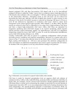
Vishay TFDS4500 Serial Infrared Transceiver
The TFDU4100, TFDS4500 (Figure 2.4), and TFDT4500 are a family of
low-power infrared (IR) transceiver modules compliant to the IrDA
standard for serial infrared (SIR) data communication, supporting
IrDA speeds up to 115.2 kb/s. Integrated within the transceiver mod-
ules is a photo PIN diode, infrared emitter (IRED), and a low-power
analog control integrated circuit (IC) to provide a total front-end solu-
tion in a single package. Telefunken’s SIR transceivers are available in
three package options, including our BabyFace package (TFDU4100),
once the smallest SIR transceiver available on the market. This wide
selection provides flexibility for a variety of applications and space
constraints. The transceivers are capable of directly interfacing with a
wide variety of I/O chips, which perform the pulse-width modula-
tion/demodulation function, including Telefunken’s TOIM4232 and
TOIM3232. At a minimum, a current-limiting resistor in series with
the IRED and a VCC bypass capacitor are the only external compo-
nents required to implement a complete solution.
Chapter 2 / Robotic System Overview
17
Figure 2.3
MCP 2150 chipset.
Figure 2.4
The vishay
TFDS4500.
PDA 02 5/27/03 8:20 AM Page 17