McGraw-Hill Build a Remote Controlled Robot Part 4 pdf
Bạn đang xem bản rút gọn của tài liệu. Xem và tải ngay bản đầy đủ của tài liệu tại đây (189.77 KB, 15 trang )
BODY FRAMEWORK
Q
uestor’s body is made from five 8-foot ϫ 1-inch ϫ 1-inch ϫ
1/8-inch strips of aluminum angle. I chose this material
over wood or plastic because while slightly more expensive, it
is stronger and more lightweight. Also, if care is taken, alu-
minum is relatively easy to work with. The aluminum angle is
used to form two boxes. These boxes are called the upper
framework and the lower framework. Once joined, they make
up Questor’s body.
Before the boxes are constructed each section of alu-
minum angle used to make up that portion of the body is
marked and drilled with holes to be used later in the robot’s
construction. These predrilled holes are best made when the
framework is in pieces rather than when assembled. A chart
will list how to assemble each box so all the predrilled holes
are in their proper locations when the framework is complete.
Remember to take your time and not to cut or drill the alu-
minum angle until you have checked your measurements or
hole locations against the book.
CUTTING ALUMINUM
Figure 2-1 shows how to cut each of the five aluminum strips
into the pieces that make up Questor’s framework. Cut the
strips with a hack saw and use a miter box to achieve straight
cuts. Be careful not to cut the aluminum before you have
checked your measurements.
13
CHAPTER
TWO
Copyright 2002 The McGraw-Hill Companies, Inc. Click Here for Terms of Use.
FIGURE 2-1.
Aluminum angle cutting guide.
14
Once you have cut the strips into pieces, separate them
so that you have four 36-inch, four 6-inch, six 10-inch, and
ten 20-inch pieces. Keep all the extra aluminum for use
later.
Now that you have the various pieces grouped together,
check to see if they are all the same length. If the pieces are
slightly unequal, simply choose the shortest piece of that
group and cut or file the others down to match it. After all the
pieces have been grouped and trimmed, they must be
predrilled and some pieces precut before assembly. This
preparation will save you a lot of time and trouble later.
DRILLING AND CUTTING THE SECTIONS
Many of the holes to be drilled now are not utilized until later
in the robot’s construction. It is much easier to drill them now
while the framework is in pieces than later when it is assem-
bled. All the cuts to be made consist of 45-degree angles.
These cuts are at the ends of one side of some of the pieces
and allow them to be joined into squares with no overlap.
Figure 2-2 shows an example of this.
Figures 2-3 through 2-26 illustrate how each piece of alu-
minum is drilled or cut. Each figure consists of two rectan-
gles; one rectangle represents each of the outer surfaces of
BODY FRAMEWORK 15
TABLE 2-1. Parts List
AMOUNT
ITEM
5 8-foot ϫ 1-inch ϫ 1-inch ϫ 1/8-inch angle aluminum
50 1/8-inch pop rivet (and rivet gun)
8 1-inch ϫ 5/32-inch-diameter bolt, nut, and
lockwasher set
6 1-inch ϫ 1/4-inch-diameter bolt, nut, and
lockwasher set
1 Vacuum cleaner kit
FIGURE 2-2. Angles cut so pieces can be joined at corners.
FIGURE 2-3. Drilling and cutting guide.
FIGURE 2-4. Drilling and cutting guide.
FIGURE 2-5. Drilling and cutting guide.
FIGURE 2-6. Drilling and cutting guide.
FIGURE 2-7. Drilling and cutting guide.
BODY FRAMEWORK 19
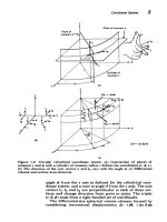
that piece. The figures depict each piece as if it were laid
lengthwise with its two edges on a workbench then flattened
so both sides could be seen. All the figures show the locations
and diameter of the holes to be drilled. The locations of the
45-degree angle cuts to be made at the ends of many of the
aluminum pieces are shown as shaded areas where the alu-
minum is to be removed.
Most of the figures are duplicates of each other. The dif-
ference between the figures are numbers and sometimes let-
ters that appear on the sides of each aluminum piece. The
numbers are used when the framework is assembled to the
two main sections that make up Questor’s body. The letters
are used when these sections are joined together by two con-
necting pieces to form the completed framework. In both
cases the symbols ensure that all the predrilled holes are
in their correct locations when the framework is completed.
To mark the numbers and letters on the outsides of each
FIGURE 2-8. Drilling and cutting guide.
20 CHAPTER TWO
FIGURE 2-9. Drilling and cutting guide.
BODY FRAMEWORK 21
FIGURE 2-10. Drilling and cutting guide.
22 CHAPTER TWO
FIGURE 2-11. Drilling and cutting guide.
BODY FRAMEWORK 23
FIGURE 2-12. Drilling and cutting guide.
24 CHAPTER TWO
FIGURE 2-13. Drilling and cutting guide.
FIGURE 2-14. Drilling and cutting guide.
BODY FRAMEWORK 25
FIGURE 2-15. Drilling and cutting guide.
FIGURE 2-16. Drilling and cutting guide.
26 CHAPTER TWO
FIGURE 2-17. Drilling and cutting guide.
FIGURE 2-18. Drilling and cutting guide.
BODY FRAMEWORK 27
FIGURE 2-19. Drilling and cutting guide.
FIGURE 2-20. Drilling and cutting guide.