Mechanics of Microelectromechanical Systems - N.Lobontiu and E.Garcia Part 12 doc
Bạn đang xem bản rút gọn của tài liệu. Xem và tải ngay bản đầy đủ của tài liệu tại đây (902.01 KB, 30 trang )
318
Chapter 5
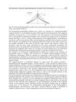
Figure 5.53 Bifurcation versus snap-through buckling
The buckling cases discussed so far (and which are retrieved in
significant numbers of MEMS applications) were produced by
bending/flexure. There are however cases where buckling is generated
through torsion (such as for thin-walled open-section members) or through
mixed bending and torsion (for coupled bending-torsional cases), but these
situations are beyond the scope of this presentation. Also, from a structural
standpoint, members that can buckle include columns (which can sustain
only axial loads), beam-columns (which can sustain bending loads, in
addition to axial loads), rigid frames (which are formed of two or more
rigidly-attached beam-columns), or plates/membranes. The presentation will
be limited here to columns and beam-columns (both straight and curved), as
the majority of buckling-related MEMS applications are based on these
structural members.
Buckling can be either elastic or inelastic, depending on the way the
buckling stresses do compare to the proportionality limit which is shown
in the plot of Fig. 5.54 for a ductile material. Long and thin (slender)
columns for instance buckle at stress levels that are less the proportionality
limit, where the stress-strain characteristic becomes non-linear (the material
no longer obeys the Hooke’s linear relationship). This type of buckling is
therefore elastic and this is the desired form of buckling in MEMS
applications, as the microcomponent recovers its original shape after the load
has been removed. Relatively short components are generally prone to
inelastic buckling, as part of their cross-section is already in the non-linear
portion of the stress-strain characteristic of Fig. 5.54 (the 2-3 portion), and
therefore this type of buckling is inelastic, so the micromember does not
completely regain its original shape. Unless the buckled micromember is
going to be discarded, this condition is to be avoided in buckling design.
5. Static response of MEMS
319
Figure 5.54 Stress-strain curve for a ductile material
7.2
Columns and Beam-Columns
Columns and beam-columns (straight, curved and bent) will be studied
next by analyzing their behavior in the elastic domain.
7.2.1
Straight Beam-Columns
The main problem with the elastic buckling is establishing the minimum
compressive force (the critical load), which is capable of producing buckling.
One method of solving this problem is formulating and solving the
differential equation of a column subjected to axial compressive load. Most
often, the pinned-pinned configuration of Fig. 5.55 is taken as the paradigm
example, and will also be utilized here.
Figure 5.55 Pinned-pinned column in buckling.
The pinned-pinned column is originally straight and its length is 1. Figure
5.55 shows it in buckled condition and indicates the generic deflection
which is generated through the action of the compressive axial load F applied
at the moving pinned end. The differential equation governing the static
bending of this member is:
320
Chapter 5
As Fig. 5.55 indicates, the bending moment is:
such that substitution of Eq. (5.149) into Eq. (5.148) results in:
where:
From basic differential calculus, it is known that the solution to the
homogeneous differential equation (5.150) is of the form:
where A and B are integration constants that are determined from the
boundary conditions. When x = 0, the deflection at that point is
and Eq. (5.152) gives A = 0. Similarly, when x = 1, which, after
substitution into Eq. (5.152), gives the non-trivial solution:
Equation (5.153) is equivalent to:
which, combined to Eq. (5.151), gives the equation of the forces that produce
buckling as:
Out of the set of forces that are obtained when n = 1, 2, 3, , the critical
buckling load is the smallest one, corresponding to n = 1, and therefore:
Boundary conditions that are different from the ones of Fig. 5.55 are also
possible in other buckling-related problems, as shown in Fig. 5.56. The
5. Static response of MEMS
321
critical buckling load can be calculated for each case following the procedure
used in determining the critical load for a pinned-pined column, as detailed in
Chen and Lui [6] or Chajes [7]. The critical load can be expressed in the
generic manner:
where is called the effective length and is calculated by means of the
effective-length factor K as:
Figure 5.56 Combinations of ideal boundary conditions for beam-columns in buckling: (a)
guided-fixed (K = 0.5), (b) pinned-fixed (K = 0.7), (c) pinned-pinned (K = 1), (d) fixed-fixed
(K = 1), (e) free-fixed (K = 2), (f) fixed-pinned (K = 2)
Figure 5.56, which shows other combinations of boundary conditions for
beam-columns subjected to buckling, also gives the corresponding values of
K – after Chen and Lui [6].
Another measure of the elastic buckling is the critical stress, which is
produced by the compression load, and which can be calculated as:
By using the radius of gyration, which is defined as:
322
Chapter 5
and the slenderness ratio, which is:
the critical stress of Eq. (5.159) becomes:
The critical stress is plotted against the slenderness ratio in Fig. 5.57.
Figure 5.57 Plot of critical stress against the slenderness ratio
The curve denoted by 1 is the graphical representation of the critical stress –
slenderness ratio of Eq. (5.162), and therefore the elastic buckling is only
possible for values lager than the value which corresponds to the material
proportionality limit. For values smaller than which apply to shorter
columns – as the definition Eq. (5.161) shows it, the column might buckle
inelastically (the portions 2 or 3) or, for very short columns, buckling is not
even possible (the segment denoted by 4). The curve 2 for instance represents
the Engesser model for inelastic buckling, which uses a formula similar to
the one corresponding to the elastic buckling of Eq. (5.162). The only
difference with this model is that Young’s modulus is no longer constant, and
is taken as either the tangent or secant value from the experimental stress-
strain curve, or as an average combination of the two values. Another
solution is the Tetmajer-Jasinski model, which expresses a linear relationship
between the critical stress and the slenderness ratio. While the Engesser
model works better for metallic components, the Tetmajer-Jasinski model is
5. Static response of MEMS
323
more appropriate for aluminum-type materials – Chen and Lui [6]. In MEMS
devices, however, the inelastic buckling is not desirable, and redesign has to
be performed when a component is plausible to buckle inelastically.
Example 5.21
A guided-fixed beam-column, as the one sketched in Fig. 5.56 (a), which
is intended to function as an out-of-the-plane actuator, is designed by mistake
such that Take the necessary measures in order for the beam
column to operate reliably as an actuator. The material of the
microcomponent cannot be changed and the length is also specified.
Solution:
Because the beam-column will eventually buckle inelastically, as
shown in Fig. 5.57, and this is an undesired condition. For elastic buckling it
is necessary that the redesigned component have a slenderness ratio larger
than the proportionality limit. By considering a rectangular cross-section
defined by w and t (w being the in-plane dimension, and w > t), the
slenderness ratio in the initial design can be expressed as:
when taking into account that:
Obviously, the new slenderness ratio (of the redesigned microactuator) is
expressed similarly as:
and the intention is that:
in order to insure that the new slenderness ratio is at least equal to the
proportionality limit so that buckling takes place in the elastic domain.
Combination of Eqs. (5.163), (5.165) and (5.166) results in the following
relationship:
324
Chapter 5
One way of realizing condition (5.167) is to change the current boundary
conditions such that K increases. The highest theoretical value of K is 2, as
shown in Fig. 5.56, and this corresponds to either a free-fixed condition – Fig.
5.56 (e) or a fixed-pinned one – Fig. 5.56 (f). This provision would transform
Eq. (5.167) into:
because and as indicated in Fig. 5.56. As a consequence, the
microactuator will buckle elastically when the boundary is modified
according to the previous discussion and when the cross-section thickness is
reduced by at least 20%.
7.2.2
Curved Beam-Columns
A pinned-pinned thin curved beam of small curvature is now analyzed,
as the one sketched in Fig. 5.58, in order to find its critical load by means of
the energy method.
Figure 5.58 Pinned-pinned curved beam of small curvature under axial loading
The original shape of the beam is drawn with thick solid line, whereas the
deformed (buckled) shape is shown with a dotted line. The original offset of
the curved beam at a position x is denoted by and the maximum offset
a is located at the midpoint of the beam whose span is 1. The extra-
deformation gained through axially-produced bending is denoted by
for the x-position. By following the standard procedure that enables finding
the deformed shape of a pinned-pinned beam and under the assumption that
the original curved shape of the beam is defined as:
Timoshenko [4] derived the following solution for the bent shape of the
curved beam:
5. Static response of MEMS
325
The energy method which is utilized here as an alternative tool of
calculating the critical load states that the strain energy stored in a deformed
member is equal to the external work performed by the loads. In the case of
the small-curvature beam of Fig. 5.58, only the bending effects have to be
accounted for. As a consequence, the strain energy stored in the beam
through bending is expressed as:
The bending moment is produced by the axial force and is equal to:
By substituting Eqs. (5.170) and (5.172) into Eq. (5.171), the strain energy
can be calculated as:
The work in this case is produced by the force F traveling over a distance
about the x-axis, namely:
The travel by the force F can be calculated as:
By taking the x-derivative of of Eq. (5.170) and by substituting it into
Eq. (5.175), the work of Eq. (5.174) becomes:
By considering the statement of the energy principle, namely:
it can be found that the critical force is equal to the critical force
corresponding to a straight pinned-pinned beam.
326
Chapter 5
The advantage of the curved design, as well as of the next design
presented herein (the bent beam column), over the straight configuration is
that the curved beam-column produces buckling unidirectionally (outside the
curvature center), as it is improbable that buckling will occur the other
direction. This feature can be used in applications where buckling is sought
not to take place about certain directions, such as towards the substrate. At
the same time, the buckling direction of a straight beam-column is
completely unpredictable.
7.2.3
Bent Beam Columns
A design which is similar to the small-curvature curved beam of Fig.
5.58 is the one sketched in Fig 5.59. It consists of two symmetric beams
which are rigidly attached at the middle of the span 1, and are slightly
inclined, making a small angle with the line joining the two end pins. This
design, with different boundary conditions, was studied in the
sensing/actuation chapter, when dealing with the bent beam thermal actuator.
It is worth emphasizing that when the axial force is less than the critical
buckling load, the microstructure still bends, although not through buckling,
and this is also valid for the curved beam of the previous sub-section.
Figure 5.59 Pinned-pinned bent beam under axial loading
Determining the critical load can be done by using the energy method,
similarly to the procedure applied to the curved beam. The loading by the
force F is statically-equivalent to the loading by a force applied at the
beam’s midpoint, as shown in Fig. 5.60. The two loading systems are
equivalent when the areas of the two bending moment diagrams are equal, as
shown by Timoshenko [4], namely when:
The initial offset of a generic point of the bent beam of Fig. 5.60 is:
5.
Static response of MEMS
327
Figure 5.60 Equivalent loading of the pinned-pinned bent beam
The deformation produced through bending by the action of the force can
simply be found by integrating the following differential equations:
and by using the appropriate boundary conditions that are zero deflections at
points 1 and 3‚ as well as equal deflections and equal slopes at point 2. It can
be shown that the total offset of the deformed beam is:
where:
By using Eqs. (5.171) and (5.181)‚ it is found that the strain energy is equal
to:
The work done by the axial force is:
By equating the strain energy U to the work W‚ according to the energy
principle‚ gives the expression of the critical force:
328
Chapter 5
which is also the solution for a straight beam of length l.
7.3
Post Buckling and Large Deformations
The critical load is found by means of the small-displacement theory‚ and
this cannot predict the displacement/deformations of a beam-column at
buckling or for conditions where the axial load exceeds the critical value.
However‚ as mentioned previously‚ MEMS applications are being
specifically designed to produce large output displacement through buckling
and therefore knowledge of the true deformation of a buckled member is
important. By using the large-deformation theory it is possible to predict the
so-called post-buckling behavior of a microcomponent‚ as shown next.
Figure 5.61 Postbuckling and large deformations: (a) straight guided-fixed column; (b)
same column in buckled condition; (c) one-quarter length free-fixed column; (d) free-fixed
column
The straight guided-fixed column of Fig. 5.61 (a) is the model for many
MEMS components that utilize buckling/postbuckling to achieve either large
displacements or actuation forces. When the axial force F exceeds the critical
buckling value‚ large deformations are set and the column deflects as shown
in Fig. 5.61 (b). The buckled shape of Fig. 5.61 (b) can be divided in four
equal segments‚ one of them (of free-fixed boundary conditions) being
shown in Fig. 5.61 (c). As Fig. 5.61 (b) suggests‚ there is a relationship
between a guided-fixed column and a free-fixed one‚ the latter having the
length equal to one quarter the length of the former‚ as mentioned by
Timoshenko [4]‚ for instance.
One consequence of this one-quarter-length relationship is that the
buckling load of the guided-fixed column can be calculated from the
5.
Static response of MEMS
329
buckling load of the free-fixed column by using 1/4 instead of 1. Another
important consequence is that the maximum postbuckling deflection of the
guided-fixed column is twice the maximum postbuckling deflection of a free-
fixed column with one quarter length‚ as shown in Figs. 5.61 (b) and (c).
Calculating the maximum deflection of a free-fixed column is relatively
easier and it follows the path described previously when studying the large
deflections of a free-fixed beam under the action of a transverse force.
Figure 5.61 (d) is used to briefly formulate the maximum deflection of a
postbuckled free-fixed column. By using the same reasoning that has been
applied for the beam under the action of a transverse load – Fig. 5.44 – it can
be shown that:
where ds‚ and are indicated in Fig. 5.44 and k is given in Eq. (5.134).
Equation (5.186)‚ coupled to Eq. (5.133)‚ gives the length of beam-column
as:
Equation (5.187) is used to determine the force F (which is embedded in k by
way of Eq. (5.134)) corresponding to a certain value of the tip slope The
maximum tip deflection is found by combining Eqs. (5.186) and (5.131)‚
namely:
Example 5.23
Determine the maximum deflection of a guided-fixed microcolumn as
the one sketched in Fig. 5.61 (a) under the compressive action of a force
knowing and E = 160 GPa.
Solution:
The critical load of a free-fixed microcolumn having the length equal to
1/4 the length of the analyzed microcolumn is determined by means of Eqs.
(5.157) and (5.158) and of Fig. 5.56 (e) – showing that K = 2. The critical
load is found to be equal to Solving for in Eq. (5.187) gives a
value of 100°‚ which is further utilized in Eq. (5.188) to find the maximum
tip deflection of the free-fixed beam. This value‚ as mentioned previously‚ is
half the maximum deflection of a guided-fixed microcolumn having four
330
Chapter 5
times the length of the free-fixed microcolumn‚ which gives a value of
for the sought maximum postbuckling deflection.
8.
COMPOUND STRESSES AND YIELDING
8.1
Introduction
Often times‚ normal and tangential stresses are produced concomitantly
in deformable MEMS components. In such cases‚ the loading produced
through actuation needs to ensure that the microcomponents that do deform‚
do so within the elastic range‚ so that the part regains its original shape after
loading is relieved‚ and that they do not fail.
Figure 5.62 Normal tangential and resultant (p) stresses on a cross-section
Figure 5.62 shows the cross-section of a MEMS component where
normal (perpendicular to the plane) and tangential (within the plane) stresses
are produced and combined vectorially to get the resultant stress p. The
normal stress can be produced by either bending or axial loading whereas
the tangential stress which is contained in the yz plane of the cross-section
and which has components about the principal axes y and z‚ can be generated
by torsion or shearing‚ as discussed in Chapter 1. The total stress p can be
found as:
Failure in MEMS‚ as the situation where a microcomponent does no
longer perform as expected/designed‚ can occur in the forms
of
fracture (in
the case of brittle materials)‚ yielding (for ductile materials where the stresses
exceed the yield limit)‚ excessive deformation (either elastic or plastic)‚
buckling or creep (deformation under constant load‚ especially at elevated
temperatures) – see for more details Boresi‚ Schmidt and Sidebottom [3] or
Cook and Young [8].
5.
Static response of MEMS
331
8.2
Yielding Criteria
The MEMS yielding failure will be discussed here under statical loading.
In essence‚ a compound stress resulting from normal and tangential
components needs to be less than a limit value in order for the
microcomponent to operate reliably. In order to predict the yield response of
structural components that are constructed of various materials and under
different loading conditions‚ criteria have been formulated that enable
transforming the complex loading into a simpler one‚ usually the uniaxial
tension‚ for which experimental values of the yield stress are usually
experimentally available. A brief presentation of the yield criteria that are
most common are presented next‚ but the interested reader could consult
more advanced texts dedicated to this topic‚ such as Boresi‚ Schmidt and
Sidebottom [3]‚ Ugural and Fenster [9] or Den Hartog [10]‚ to cite just a few
sources.
The von Mises theory considers that yielding begins when the distortion
energy reaches the limiting value and therefore when it is equal to the
distortion energy at yielding in a simple tension test. It is known from
strength of materials that the actual state of stress and deformation in a
component is the superposition (sum) of a hydrostatic state (which causes the
structure to modify its volume without changing its shape) and a distorsional
state (which only generates shape modification through pure-shear
mechanisms‚ without altering the structural volume). By equating the
distorsion energy corresponding to the real three-dimensional state of stress
to the distorsion energy pertaining to a uniaxial tensile stress situation‚ the
von Mises criterion (or theory) gives the following equivalent stress:
It is sometimes considered that the von Mises theory is a particular case of a
more generic theory‚ also known as the Beltrami-Haigh (total energy)
criterion‚ which states that yielding initiates when the total strain energy of a
structural component under complex loading equals the total strain energy
corresponding to yielding in an uniaxial tension/compression. A common
particular case of the general three-dimensional state of stress is the state of
plane stresses where the only non-zero stresses are the normal stress and
the tangential stress case where Eq. (5.190) reduces to:
The Tresca criterion‚ also known as the maximum shear stress theory‚
assumes that yielding most likely occurs when the maximum shear stress in a
component under complex load is equal to the maximum (yield) shear stress
332
Chapter 5
in uniaxial tension/compression. As a consequence‚ the equivalent stress by
the Tresca criterion is formulated as:
where and are the maximum and minimum values of the three
principal stresses and which can be calculated as solutions of the
third-degree algebraic equation:
with and – the stress invariant – being defined in terms of the three-
dimensional state of stress components as:
In a plane stress situation‚ the Tresca theory predicts that:
Both von Mises and Tresca yielding criteria are working well for ductile
materials.
Example 5.23
A microcantilever of constant rectangular cross-section is utilized in a
AFM reading experiment‚ where‚ at a given moment in time‚ the following
forces act at its tip‚ as shown in Fig. 5.63: and
Determine the maximum stress induced in the microcantilever when its
narrow cross-section is defined by and The length of the
microcantilever‚ is measured between the vertex of its tip and the
anchor root‚ and the distance h is equal to The microcantilever is
metallic with a yield stress of
Solution:
The most loaded cross-section of the microcantilever is the one located at
the anchor root. Bending moments and axial tension combine to produce
normal stresses‚ whereas the tangential stresses are generated by torsion
when shearing is ignored. The loading at the microcantilever’s fixed root
comprises the following components:
5.
Static response of MEMS
333
Figure 5.63
Microcantilever for AFM reading acted upon by three tip forces
The von Mises criterion reduces in the case of the constant cross-section to
the form given in Eq. (5.191).
Figure 5.64 shows the variation of the normal bending stresses under the
action of and respectively.
Figure 5.64 Bending-produced stresses over the cross-section
The bending-produced stresses are zero in the symmetry axes‚ and reach a
maximum (either positive – corresponding to tension‚ or negative –
corresponding to compression) on the outer fibers. The bending moment
334
Chapter 5
generates the normal stress and generates such that the resultant
stress is their algebraic sum at any point of the cross-section. As Fig. 5.64
shows‚ at points A and B the sum is maximum‚ positive at A and negative at
B. In addition to bending‚ the axial force N also produces tensile stresses
which are constant over the cross-section. It follows that the maximum
normal stress is found at A‚ and is tensile (positive):
It is also known – see Boresi‚ Schmidt and Sidebottom [3] for instance‚ that
for a narrow cross-section the maximum torsion-produced stress occurs also
at one of the edge points – so either A or B – and is equal to:
By recalling that the equivalent stress represents a maximum value‚ it follows
that Eq. (5.195) becomes‚ by means of Eqs. (5.196) through (5.198):
The equivalent stress of Eq. (5.199) gives which is smaller
than the yield stress.
Example 5.24
A U-spring connects to a shuttle mass as in Fig. 5.65 (a). The spring is
acted upon by the forces and The U-spring is constructed of a ductile
material with a yield stress of and the spring’s cross-section is
a narrow rectangle‚ as shown in Fig. 5.65 (b) with and
Known are also and Determine
the force which will keep the maximum stresses in the microsuspension
at the yield threshold.
Solution:
When ignoring the stresses produced by axial and shearing effects‚ the
three segments of the half-model of Fig. 5.65 (a) are subject to the combined
action of bending and torsion. The maximum moments occur at the fixed
position 4‚ namely:
5.
Static response of MEMS
335
The normal stresses in this case are produced by the two bending moments‚
and the maximum value occurs again at one vertex being of the form:
Figure 5.65 Model of a U-spring: (a) geometry and static loading; (b) cross-section
Because the cross-section is narrow‚ the tangential stress which is caused by
the torsion moment has its expression given in Eq. (5.198).The von Mises
theory results in:
which‚ by using Eqs. (5.200) and (5.201)‚ gives
For this state of stress problem‚ the Tresca criterion becomes:
The numerical data of this problem results in
Problems
Problem 5. 1
The precision-positioning microdevice shown in Fig. 5.66‚ utilizes
transverse electrostatic actuation and a spiral spring. The displacement is
336
Chapter 5
monitored by means of longitudinal electrostatic sensing in a controlled
feedback loop. Dimension the electrostatic actuator area A for an initial gap
such that minimum displacement increments can be
produced by minimum voltage increments The spiral spring is
defined by and E = 160 GPa. The
electrical permittivity is Also determine the pull-in voltage.
Figure 5.66 One-spring and electrostatic actuation
Answer:
Problem 5.2
A microaccelerometer, as the one of Fig. 5.4 (a), uses a constant
rectangular cross-section flexure hinge with cross-section
defined by and and E = 150 GPa. The tip mass has a
length and its mass is The electrical permittivity is
and the initial gap is The sensor has to be able to
detect accelerations as small as Determine the voltage that is
generated under these circumstances.
Answer:
U=10.11 V
Problem 5.3
The rotary electrostatic transducer of Fig. 5.6 (a) is used instead of the
one studied in Example 5.3. Determine the number of beam suspensions
having the cross-section defined by that will make this
microsystem perform identically to the one of Example 5.3 under identical
actuation and geometrical/material conditions.
Answer:
n = 3
5.
Static response of MEMS
337
Problem 5.4
The microaccelerometer with two flexure microhinges of Fig. 5.67 uses
double capacitance readout (parallel capacitance). Find the acceleration
knowing that the maximum capacitance variation is and the
voltage generated externally is U = 0.1 V. The microaccelerometer mass is
Also known are
(the capacitive area), as well as the parameters of the flexure microhinges:
E = 155 GPa. (Hint: The total capacitance change is
the sum of the capacitance variations at the two gaps).
Figure 5.67 Microaccelerometer with double capacitance readout
Answer:
Problem 5.5
A microdevice as the one shown in Fig. 5.68 is composed of an
electrostatic longitudinal actuator and two beam suspensions, all connected
by a central shuttle mass. The microactuator has the following defining
parameters: (the number of gaps),
and the parameters of one microbeam are:
E = 160 GPa. Find the longitudinal displacement of the shuttle mass
when a voltage U = 80 V is applied to the electrostatic actuator unit.
Figure 5.68 Microdevice with electrostatic actuation and beam suspensions
Answer:
338
Chapter 5
Problem 5.6
The microdevice in Fig. 5.69 combines electrostatic transverse actuation‚
longitudinal sensing‚ and two folded-beam microsuspensions. The actuation
unit is defined by: The sensing
unit has the following parameters: The
sensed capacitance change is for a voltage of 100 V actuation-
supplied. Determine the model displacement of the central shuttle mass‚ as
well as its real displacement for
Figure 5.69 Microdevice with electrostatic transverse actuation‚ longitudinal sensing and
folded-beam suspensions
Answer:
Problem 5.7
A torsional microdevice‚ as the one sketched in Fig. 5.70‚ is employed to
measure the magnitude of an external magnetic field B‚ which is directed as
shown in the same figure. The rotation angle is measured experimentally by
optical means and its maximum value is The radius of the current
loop is the current is and the parameters defining the
two constant cross-section torsion microhinges are
and G = 62 GPa. Find the external magnetic field B.
Figure 5.70
Electromagnetic-field sensor with two torsional microhinges
5.
Static response of MEMS
339
Answer:
B = 918.52 T
Problem 5.8
The microdevice in Fig. 5.71 is used as an angular electrostatic actuator
(as in Fig. 5.17) in an application where a rotation angle of needs to
be achieved. Find the necessary voltage knowing that:
The torsion microhinges are
defined by: and G = 80 GPa.
Figure 5.71 Angular electrostatic actuator with torsion microhinges
Answer:
U= 17.34V
Problem 5.9
The four-beam microaccelerometer in Fig. 5.72 is expected to sense an
acceleration Find the mass that will produce a displacement
of the central mass when the four identical flexure microhinges
are defined by: E = 165 GPa.
Figure 5.72 Microaccelerometer with four flexure microhinges
Answer:
340
Chapter 5
Problem 5.10
The plate of the optical chopper in Fig. 5.13 is suspended by means of
four inclined beams. Determine the minimum actuation force which is
needed to displace the plate by a quantity Ignore the plate’s self
weight‚ as well as the suspensions’ stiffness about the z-direction.
Answer:
Problem 5.11
The bimorph in Fig. 5.73 pushes the hinged mirror microplate with a
force such that an amplified out-of-the-plane motion is obtained at the
free tip of the microplate. A strain is induced in the bimorph. The
bimorph is defined by the following geometric and material parameters:
The two
identical torsion microhinges have G = 75 GPa‚ and
Also known are and Find the tip displacement
Figure 5.73
Displacement-amplification microdevice with bimorph actuation and torsion
microhinges (top view)
Answer:
Problem 5.12
Find the bloc force for a sagittal microdevice with curved flexure hinges‚
based on the quarter-model of Fig. 5.74.
Answer:
5.
Static response of MEMS
341
Figure 5.74 Reduced quarter-model of sagittal microdevice with curved flexure hinges
Problem 5.13
A fixed-free microbar having a length and cross-section area
is used in a yield tensile test‚ which indicates that the axial force
producing fracture of the microspecimen is and that the
corresponding maximum tip displacement is Find the values of
Young’s modulus according to the small- and large-deformation models.
Answer:
Problem 5.14
The slender microbeam of Fig. 5.75 is utilized to generate large
displacements through buckling by means of a thermal actuator. The
microbeam is defined by and E = 165 GPa,
and the actuator by
The axial displacement at the actuator-microbeam junction is
when a temperature increase is applied to the actuator.
Establish if this condition is sufficient to produce buckling of the microbeam.
Figure 5.75 Buckling microdevice with thermal actuation and slender beam
342
Chapter 5
Answer:
(for a guided-fixed beam); buckling
possible
Problem 5.15
A microplate supported by two carbon nanorods of circular cross-section
is used to sense external magnetic fields by means of a current loop‚ as
shown in Fig. 5.76. Find the maximum torsion angle that would keep the
stresses in the nanorods under an allowable limit Known are the radius of
the nanorods circular cross-section‚ r‚ their length l and the shear modulus G.
Figure 5.76 Magnetic microsensor with torsion nanorods
Answer:
References
1. W. Geiger et al.‚ Decoupled microgyros and the design principle DAVED‚ Sensors and
Actuators A‚ 95‚ 2002‚ pp. 239-249.
2. R. Sattler‚ F. Plotz‚ G. Fattinger‚ G. Wachutka‚ Modeling of an electrostatic torsional
actuator: demonstrated with an RF MEMS switch‚ Sensors & Actuators A‚ 97-98‚ 2002‚ pp.
337-346.
3.
A.P. Boresi‚ R.J. Schmidt‚ O.M. Sidebottom‚ Advanced Mechanics of Materials‚ Fifth
Edition‚ John Wiley & Sons‚ Inc.‚ New York‚ 1993.
4. S.P. Timoshenko‚ Theory of Elastic Stability‚ McGraw-Hill Book Company‚ New York‚
1936.
5. J.M. Gere‚ S.P. Timoshenko‚ Mechanics of Materials‚ Third
Edition‚ PWS-KENT
Publishing Company‚ Boston‚ 1990.
6. W.F. Chen‚ E.M. Lui‚ Structural Stability. Theory and Implementation‚ Elsevier‚ New York‚
1987.
7.
A. Chajes‚ Principles of Structural Stability Theory‚ Prentice Hall‚ Englewood Cliffs‚ 1974.
8. R.D. Cook‚ W.C. Young‚ Advanced Mechanics of Materials‚ Macmillan Publishing
Company‚ New York‚ 1985.
9. A.C. Ugural‚ S.K. Fenster‚ Advanced Strength and Applied Elasticity‚ Third Edition‚ PTR
Prentice Hall‚ Englewood Cliffs‚ 1995.
10.
1. J.P. den Hartog‚ Advanced Strength of Materials‚ Dover Publications‚ New York‚ 1987.
(Eq. (4.7)),