Mechatronics for Safety, Security and Dependability in a New Era - Arai and Arai Part 8 pdf
Bạn đang xem bản rút gọn của tài liệu. Xem và tải ngay bản đầy đủ của tài liệu tại đây (3.34 MB, 30 trang )
194
Ch40-I044963.fm Page 194 Tuesday, August 1, 2006 8:21 PM
Ch40-I044963.fm Page 194 Tuesday, August 1, 2006 8:21 PM
194
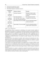
CONCLUTION
Tn this paper,
we
described
the
safety design
for the
small biped-walking home-entertainment robot
SDR-4XTT
and the
outline
of the
robotic actuator ISA-4 which contributes
to the
safety management
of
the robot.
The
cross relationships between functions
and
features
are
shown
in
Figure
12.
As SDR-4XII
is
designed
to be
used
in a
home environment,
we had to
encounter several problems
for
its
safe operation. Therefore
we
developed
new
ingenious functions described
in
this paper
and
settled
the
problems.
Mechanical design —r-
Functions of ISA-4
—
•A
-fl
tl
H
- I
-A
Sinfpfy ff at^irfc
Safety cover design
Pinching detection
Lifting up and holding motion control
Over temperature detection
Overload detection
Shock impact detection
Falling over motion control
}
\
1
)
H
h
h-
~i
i
j
-
User Protection
-
Robot Protection
Contribution
•
Figure
12:
Cross relationship between functions
and
features
REFERENCES
Collins,
H.S.,
Wisse,
M.,
Ruina,
A.
(2001),
"A
Three-Dimensional Passive-Dynamic Walking Robot
with
Two
Legs
and
Knees",
Int.
Journal of Robotics Research, Vol.20,
No.7,
pp.607-615.
Fujita,
M.,
Kageyama,
K.
(1997),
"An
Open Architecture
for
Robot Entertainment", Proc.
Int. Con-
ference
on
Autonomous Agents
1997,
pp.435-450 .
Fujiwara,
K.,
Kanehiro,
F.,
Kajita,
S.,
Yokoi,
K., et al.
(2003),
"The
First Human-size Humanoid that
can Fall Over Safely
and
Stand-up Again", Proc. IEEE/RSJ Int. Conference of Intelligent Robotics
and
Systems 2003, pp. 1920-1926.
Fukushima,
T.,
Kuroki,
Y.,
Ishida,
T.
(2004), "Development
of a New
Actuator
for a
Small Biped
Walking Entertainment Robot-Using
the
optimization technology
of
Electromagnetic Field Analysis",
Proc.
ISR
2004.
Iribe,
M.,
Fukushima,
T.,
Yamaguchi,
J.,
Kuroki,
Y.
(2004), "Development
of a New
Actuator
for a
Small Biped Entertainment Robot Which
has
Suitable Functions
for
Humanoid Robots", Proc.
The
30
th
Annual Conference
of
the IEEE Industrial Electronics Society 2004.
Iribe,
M.,
Moridaira,
T.,
Fukushima,
T.,
Kuroki,
Y.
(2004), "Safety design
for
small biped walking
home entertainment robot SDR-4XII", Proc.
The 5
th
Int.
Conference
on
Machine Automation 2004,
pp.303-308.
Kuroki,
Y.,
Fujita,
M.,
Ishida,
T.,
Nagasaka,
K.,
Yamaguchi,
J.
(2003),
"A
Small Biped Entertainment
Robot Exploring Attractive Applications", Proc. of the IEEE Int. Conference
on
Robotics
&
Automation
2003.
Kuroki,
Y.,
Fukushima,
T.,
Nagasaka,
K.,
Moridaira,
T., Doi, T.,
Yamaguchi,
J.
(2003),
"A
small Biped
Entertainment Robot Exploring Human-Robot Interactive Applications", Proc.
The 12th Int.
IEEE
Workshop
on
Robot
and
Human Interactive Communication 2003,
303.
Takenaka,
T.
(2001), "Honda humanoid robot "ASIMO"
",
Report
of
Honda foundation, No.99.
Yamaguchi,
J.,
Takanishi,
A.,
Kato,
I.
(1996), "Stabilization
of
Biped Walking
and
Acquisition
of
Landing Surface Position Information Using Foot Mechanism with Shock Absorbing Material",
Journal
of
the Robotics Society of Japan, Vol.14
No.l,
pp.67-74.
195
Ch41-I044963.fm Page 195 Tuesday, August 1, 2006 3:54 PM
Ch41-I044963.fm Page 195 Tuesday, August 1, 2006 3:54 PM
195
A STUDY ON A REAL-TIME SCHEDULING OF
HOLONIC MANUFACTURING SYSTEM
- COORDINATION AMONG HOLONS BASED ON
MULTI-OBJECTIVE OPTIMIZATION PROBLEM -
Koji TWAMURA
1
, Yota SEKT
1
, YoshitakaTANTMTZU
1
, Nobuhiro SUGIMURA
1
1
Graduate School of Engineering, Osaka Prefecture University,
1
-1 ,
Gakuen-cho, Sakai, Osaka 599-8531, Japan
ABSTRACT
This paper deals with a real-time scheduling system tor HMS (Holonic Manufacturing System). A new real-time
scheduling method for HMS is proposed, in the paper, to consider both the objective functions of the individual
holons and the whole HMS. In this method, all the pareto optimal combinations of the resource holons and the job
holons for the machining processes are generated based on the objective functions of the individual holons.
Following this, a most suitable combination is selected from the pareto optimal ones, based on the objective
functions of the whole HMS, such as the total make span and the total tardiness.
KEYWORDS
Holonic Manufacturing System, Real-time scheduling, Multi-objective optimization, Coordination
INTRODUCTION
Recently, automation of manufacturing systems has been much developed aimed at realizing flexible small
volume batch productions. New distributed architectures of manufacturing systems have been proposed to realize
more flexible control structures of the manufacturing systems, in order to cope with the dynamic changes in the
volume and the variety of the products and also the unforeseen disruptions, such as malfunction of manufacturing
equipment and interruption by high priority jobs. They are so called as autonomous distributed manufacturing
systems, biological manufacturing systems, and holonic manufacturing systems
[l]-[6].
In the previous report [6], decision making processes using effectiveness values have been proposed and applied
to the real-time scheduling problems of the HMS (Holonic Manufacturing System), and it was shown, through
case studies, that the proposed methods generate suitable schedules from the view point of the objective functions
of the individual holons. New systematic methods for the individual holons in the HMS are proposed, in the paper,
to consider both the objective functions of the individual holons and the whole HMS. The proposed methods are
verified through case studies.
196
Ch41-I044963.fm Page 196 Tuesday, August 1, 2006 3:54 PM
Ch41-I044963.fm Page 196 Tuesday, August 1, 2006 3:54 PM
196
REAL-TIME SCHEDULING PROCESSES OF HOLONS
Real-time Scheduling of Holons
New real-time scheduling process of the individual holons is proposed to select a suitable combination of the
resource holons and the job holons which can carry out the machining processes in the next time period. The
resource holons and the job holons mean here the equipment carrying out the machining processes and the
work-pieces to be machined, respectively.
At the time t when some machining processes are finished, and some resource holons and job holons become
'idling' status, all the 'idling' holons select their machining schedules in the next time period. The real-time
scheduling processes consist of following five steps.
(1) Collection of status data
The individual 'idling' holons firstly gather the status data from the other holons.
(2) Selection of candidate holons
The individual 'idling' holons select all the candidate holons for the machining processes in the next time period.
(3) Evaluation of objective function values of individual holons
The individual 'idling' holons evaluate the objective function values for the cases where a holon selects candidate
holons for the next machining process.
(4) Generation of all pareto optimal combinations based on objective functions of individual holons
The individual holons send the selected candidates and their objective function values to the coordination holon.
The coordination holon generates all pareto optimal combinations of the job holons and the resource holons which
can carry out the machining processes in the next time period, based on their objective function values. The pareto
optimal combinations means that there are no feasible combination which will improve the objective function
value of one holon without degrading the objective function value of at least one another holon [7].
(5) Determination of suitable combination based on objective functions of whole HMS
The coordination holon selects a most suitable combination of the job holons and the resource holons from the
pareto optimal combinations, from the view point of the objective functions of the whole HMS.
Evaluation of Objective Functions of Individual Holons
The objective functions of the individual holons were proposed in the previous research [6], as shown in Table 1.
The individual holons have one of the objective functions. The objective functions are evaluated by referring to the
following technological information representing the machining process and machining capability of all the job
holons and the resource holons.
Ms,:
Mi machining process of the job holon i (i= 1,
•••,«) ,
(k=\,
••',/?) .
Rjhn'.
m-\h candidate of resource holon, which can carry out the machining process MR (m=\, "\f}-
Tih
n
:
Machining time in the case where the resource holon
_/?«,„
carries out the machining process Mn,
W{.
Waiting time until the job holon i becomes idle if it is under machining status.
AQk'- Required machining accuracy of machining process M,% It is assumed that the machining accuracy is
represented by the levels of accuracy indicated by 1,2, and 3, which mean rough, medium high, and high accuracy,
individually.
The individual resource holons have the following technological information representing the machining
capability of the resource holons for the machining process M*-
W
m
: Waiting time until the resource holon R^ becomes idle if it is under machining status.
Qkn,:
Machining accuracy in the case where the resource holon
R
jkm
carries out the machining process M
ik
.
jfo,,
is also represented by the levels of 1,2 and 3.
n
Machining cost in the case where the resource holon R^,, carries out the machining process Afe.
197
Ch41-I044963.fm Page 197 Tuesday, August 1, 2006 3:54 PM
Ch41-I044963.fm Page 197 Tuesday, August 1, 2006 3:54 PM
197
TABLE 1
OBJECTIVE FUNCTIONS OF HOLONS
Objective fimctions
Resource
Holon
Job
Holon
Efficiency
Machining
Accuracy
Flow Time
Machining Cost
Objective function values
S Machining Time / Total Time
S (Machining Accuracy of Resources -
Required Machining Accuracy of Jobs)
I (Machining Time + Waiting Time)
S (Machining Cost of Resources)
The following procedures are provided for the job holons to evaluate the objective ftinctions. Let us consider ajob
holon i at time t. It is assumed that JTj., and JQ.
t
give the total time after the job holon / is inputted to the HMS and
the machining cost, respectively. If the job holon i selects a candidate resource holon/ (=
Rfh,,)
for carrying out the
machining process
M&,
the flow time JTj.
M
(J) and the machining costs JQ.i+\(j) are estimated by the following
equations.
0)
(2)
JCi,
+l
Q)=JG,+MCO
ikl
-
As regards the resource holons, the following equations are applied to evaluate the efficiency
MEj.,+\(i)
and the
machining accuracy
MAj.i+\(i),
for the case where a resource holon j (= Rn
m
) selects a candidate job holon / for
carrying out the machining process M&.
(i)= -(ME/.
t
TTj.
t
+ T
i
MAj.,
H
(i)=MA
H
+
•T
V
+W) (3 )
(4)
where,
77}., , ME}., ,
and MAj.
t
show the total time after the resource holon/ starts its operations, the efficiency, and
the evaluated value of machining accuracy of the resource holon
j ,
respectively. Eqn. 3 contains the minus sign in
order to evaluate the efficiency as the minimization problem.
The holons may select to wait in the next time period without executing any machining processes. In this case, the
objective ftinctions of the individual holons are evaluated by the following equation.
./WO) = max {JTi.md)}
j=\.—.r
JQ.
w
(0)=max {JC,
M
(f)}
Jir
(5)
(6)
(7)
(8)
where, /and S are the number of candidate resource holons for the job holon /, and the number of candidate job
holons for the resource holon
j ,
respectively. Eqn. 5 to 8 mean that these objective function values are defined by
the worst values of all the candidate resource holons, if they select waiting.
COORDINATION AMONG HOLONS BASED ON MULTI-OBJECTIVE OPTIMIZATION PROBLEM
Pareto Optimal Combination of Holons
After the individual holons evaluate the objective ftinctions, the coordination holon generates all pareto optimal
combinations of the job holons and the resource holons, which carry out the next machining processes. The
198
Ch41-I044963.fm Page 198 Tuesday, August 1, 2006 3:54 PM
Ch41-I044963.fm Page 198 Tuesday, August 1, 2006 3:54 PM
198
TABLE 2
COMBINATION OF RESOURCE AND JOB HOLONS
wait
Jobl
Job2
Job£
wait
flio
tf20
ago
Resouce l
an
«21
Resource 2
aoi
an
Oil
am.
Resource ^
ao
r
a\
y
air
as
r
procedur e
for
generatin g
all
paret o optima l combination s
is
formalize d
as a
multi-objectiv e optimizatio n problem ,
and
the
paret o optima l combination s
of
the jo b holon s
and the
resourc e holon s
are
define d
as
follows .
A matri x
A =
{<%•
(/ = 0, 1,
• •
•, S,j' = 0, 1,
• •
•, /}}
give s
the
combination s of job holon s
and
resourc e holons ,
as
show n
in
Tabl e
2.
Wher e
a,j= 1, if
the
job
holo n
i is
machine d
by the
resourc e holon /
in the
nex t tim e period .
Otherwise ,
ay = 0. If the job
holo n
i or the
resourc e holo n
j
wait s
in the
nex t tim e period , a®
= 1 or ay = 1.
Otherwise , a®
= 0 or a
Oj
= 0.
Onl y
one job
holo n
is
machine d
by one
resourc e holon , therefore ,
the
followin g
equation s shal l
be
satisfied .
S
a,,= \
;=0
2=1,2 ,
•",< ?
y=1,2,
•••, y
(9)
(10)
If A
is
determined ,
the
objectiv e functio n value s
x, (A) of the job
holo n
i and the
one s
x
R
(A) of the
resourc e
holon /
are
give n
by
followin g equations , respectively .
' = 1,2, ••-,<?
(11)
(12)
where , JOF,{j)
and
ROFfi)
are the
objectiv e functio n value s
of
the
job
holo n
/ and the
resourc e holon y give n
by
followin g equations .
ROFj(i) = MEj,
+l
(i) or MAj,
H
(f)
(14 )
The objective s
of the
individua l holon s
are to
minimiz e thei r objectiv e functio n values , therefore ,
the
objectiv e
function s
for
coordinatio n amon g holon s
are
give n
by
followin g equation s
as the
multi-objectiv e optimizatio n
problem .
minimized )
X(A) =
[x
l
(A) ,
•••, x (A),
x
K
(A),
•••, x
R
(A)] (15)
A *
is a
paret o optima l combination ,
if
ther e
is no A
suc h tha t
the
followin g equatio n
is
satisfied .
x£A) ^ x£A*) fora\lk,k=J
u
J2, Js,RuR2, ;Ry (16)
x{A) < x/(A*) iorstnyl,l=J\,J2,'"Jg,R\,R2,'"Jiy (17)
The coordinatio n holo n firstl y generate s
all the
candidate s
of A,
whic h represen t
all the
combination s
of
the
job
holon s
and the
resourc e holons . Thi s proces s doe s
not
tak e lon g time , sinc e
the
numbe r
of
'idling ' holon s
is
limite d
at
the
time t.
A set
ofparet o optima l combination s
{A
p
} are
secondl y obtaine d base d
on
Eqn . 16andEqn .
17.
199
Ch41-I044963.fm Page 199 Tuesday, August 1, 2006 3:54 PM
Ch41-I044963.fm Page 199 Tuesday, August 1, 2006 3:54 PM
199
Determination of Combination of Next Machining Processes
The coordinatio n holo n select s
a
suitabl e combinatio n
of
th e jo b holon s
and the
resourc e holon s from
all the
paret o
combinations , base d
on the
objectiv e function s
of
the whol e HMS .
The
followin g
two
performanc e indice s
of
the
whol e HM S
are
considere d
in
thi s research .
(1) Tota l slac k
The tota l slac k
is
give n
by the
followin g equation .
SLACK= l(d- t - TWKRi) (18 )
where ,
a, 4 and t are the
numbe r
of
the jo b holo n
in the
HMS ,
the due
dat e
of
the jo b holo n
i, and the
curren t time ,
respectively . TWKRi
is the
averag e
of the
tota l processin g tim e
of
the remainin g machinin g processe s
of
the
job
holo n /whic h
is
give n
by
following equation .
TWKRi=
E (E
T
ih
Jy)
(19 )
where ,
T
ikm
is the
machinin g tim e
in the
cas e wher e
the
m-\h (m=\, ,y) candidat e resourc e holo n carrie s
out the
Mi machinin g proces s
of
th e job holo n
/'.
/?an d
^are the
tota l numbe r
of
the machinin g processe s
of
th e jo b holo n
z,
and the
numbe r
of
the machinin g processe s finishe d
by the
curren t tim e
t.
(2)
Sum of
the rati o
of
the nex t processin g tim e
and the
remainin g processin g tim e
The
sum of the
ratio
of the
nex t processin g time
and the
remainin g processin g tim e
is
give n
by the
following
equation .
PT/TWKR= J.{T
i{
i
+l)m
/TWKRi)
(20 )
where ,
S and
TWKRi
are the
numbe r
of the
candidat e
job
holon s
in the HMS, and the
averag e
of the
tota l
processin g tim e
of the
remainin g machinin g processe s
of the job
holo n
i,
respectively . 7} ^+\yn mean s
the
machinin g tim e
of
th e nex t machinin g proces s
of
the
job holo n
/.
The coordinatio n holo n calculate s
the
tota l slac k SLACK
or the sum of
the rati o
of
th e nex t processin g tim e
and the
remainin g processin g tim e PT/TWKR
for all the
paret o combination s
{A
p
}.
Followin g this ,
the
coordinatio n holon
select s
the
combinatio n
of the job
holon s
and the
resourc e holons , whic h minimize s
the
SLACK
or
PT/TWKR.
Tha t
is, the
coordinatio n holon applie s
one of
the rule s calle d 'minimu m SLACK'
and
'minimu m PT/TWKR'.
CAS E STUD Y
Som e cas e studie s hav e bee n carrie d
out to
verif y
the
effectivenes s
of the
propose d methods .
The HMS
mode l
consistin g
of 10
machinin g center s
(MC) is
considere d
for the
case study .
The
individua l machinin g cente r holon s
have
the
differen t objectiv e function s
and the
differen t machinin g capacities , suc h
as the
machinin g tim e
7*,,, the
machinin g accurac y MAdhn,
and the
machinin g cos t
MCOihn-
As
regard s
the job
holons ,
24 job
holon s
are
considere d
in the
case study , whic h hav e
the
differen t objectiv e function s
and the
machinin g process .
8
case s
are
considere d
in the
cas e stud y
by
changin g
the
machinin g capacitie s
of
th e individua l resourc e holons .
Figur e
1
show s
the
verificatio n
of the
objectiv e function s
of the
individua l holon s
and the
whol e
HMS. The
vertica l axi s
and the
horizonta l axi s
in the
figure s
of
the left
and
middl e
are the
averag e
of
the objectiv e functio n
value s
of
all
the
holon s
and the
type
of
the objectiv e functions , respectively .
It is
foun d that
the
propose d metho d
keep s
the
objectiv e functio n value s
of
the individua l holon s
in
almos t sam e
as the
one s obtaine d
by the
previou s
method .
The
figures
in the
righ t giv e
the
averag e value s
of
the tota l tardines s
and the
tota l mak e spa n
of
all
the job
holons .
Tt is
show n tha t
the
propose d metho d improve s
the
tota l tardines s
and the
total mak e spa n whic h
are the
objectiv e function s
of
the
whol e HMS .
200
0
10
20
30
40
Flow time Cost
]setunim[ emit wolF
0
1000
2000
3000
4000
]neY[ tsoC
0
20
40
60
80
100
Efficiency Accuracy
]%[ ycneiciffE
0
3
6
9
12
15
ycaruccA
Previous method Pro
p
osed method
0
30
60
90
120
150
Total tardiness of HMS
]setunim[ ssenidrat latoT
(a) Minimum SLACK rule
0
10
20
30
40
Flow time Cost
]setunim[ emit wolF
0
1000
2000
3000
4000
]neY[ tsoC
0
20
40
60
80
100
Efficiency Accuracy
]%[ ycneiciffE
0
3
6
9
12
15
ycaruccA
Previou s metho
d
Pro
p
osed metho
d
0
10
20
30
40
50
60
70
Total make span of HMS
setunim[ naps ekam latoT
]
(b) Minimum PT/TWKR rule
Ch41-I044963.fm Page 200 Tuesday, August 1, 2006 3:54 PM
Ch41-I044963.fm Page 200 Tuesday, August 1, 2006 3:54 PM
200
CONCLUSIONS
(1) A new real-time scheduling method for the HMS is proposed, in order to generate a suitable schedule of
holons considering both the objective functions of the individual holons and the whole HMS.
(2) The proposed method is applied to the real-time scheduling problems of the HMS, and the scheduling results
are compared with the ones by the previous method. It was shown, through case studies, that the proposed
method is effective to improve the production schedules from the viewpoint of the objective functions of the
whole HMS.
REFERENCES
1.
Ueda,K. (1992). An approach to bionic manufacturing systems based on DNA-type information. Proc. qfthe
ICOOMS '92,303-308.
2.
Moriwaki, T. and Sugimura, N. (1992). Object-oriented modeling of autonomous distributed manufacturing
system and its application to real-time scheduling. Proc. qfthe ICOOMS '92,207-212.
3.
Iwata, K., et al. (1994). Random manufacturing system: A new concept of manufacturing systems for
production to order. Annals qfthe C1RP 43:1,379-384
4.
Wiendahl, H.P. and Garlichs, R. (1994). Decentral production scheduling of assembly systems with genetic
algorithm. Annals of the CIRP 43:1,389-396
5.
Wyns, J., et al. (1996). Workstation architecture in holonic manufacturing systems. Proa qfthe 28th Int.
Seminar on Manufacturing Systems, 220-231
6. Iwamura, K. et al. (2003). A study on simulation system for real-time scheduling of holonic manufacturing
system. Proa of The 7th WorldMulticonference on Systemics, Cybernetics andInformatics'8,261-266
7.
Vira C. et al. (1983). Multi-objective decision making: theory and methodology, North Holland
15
12
9
6
3
0
ccAuycar
150
| 120
^
90
a
1
60
| 30
0
Cost
Efficiency Accuracy
I D Previous method M Proposed method I
(a) Minimum SLACK rule
100 I 1 15 70
Flow time
Cost
Efficiency Accuracy
| D Previous method M Proposed method |
(b) Minimum PT/TWKR rule
Figure 1: Comparison of objective function values
Total tardiness of HMS
Total make span of HMS
201
Ch42-I044963.fm Page 201 Tuesday, August 1, 2006 3:57 PM
Ch42-I044963.fm Page 201 Tuesday, August 1, 2006 3:57 PM
201
A STUDY ON INTEGRATION OF PROCESS PLANNING AND
SCHEDULING SYSTEM FOR HOLONIC MANUFACTURING SYSTEM
- SCHEDULER DRIVEN MODIFICATION OF PROCESS PLANS-
Rajesh SHRESTHA
1
, Toshihiro TAKEMOTO
1
, Nobuhiro SUGIMURA
1
1
Graduate School of Engineering, Osaka Prefecture University,
1
-1 ,
Gakuen-cho, Sakai, Osaka 599-8531, Japan
ABSTRACT
In case of small batch productions with dynamic changes in volumes and varieties of products, the conventional
manufacturing systems are not adaptable and thus, new architectures of manufacturing system known as
autonomous distributed manufacturing system has been proposed, which can cope with dynamic changes in
volume and variety of products, and also with unscheduled disruptions. Holonic manufacturing system is one of
the autonomous distributed manufacturing systems. The purpose of the present research is to develop an integrated
process planning and scheduling system, which is applicable to the HMS. In this research, the process plans of the
individual product are modified with the help of the feedback information of the generated schedule. A systematic
method based on the DP and the heuristic rule is proposed to modify the predetermined process plans, based on
the load balancing of the machining equipment.
KEYWORDS
Holonic Manufacturing, Scheduling, Process Planning, Dynamic Programming, Heuristic Rule
INTRODUCTION
In case of small batch productions with dynamic changes in volumes and varieties of products, the conventional
manufacturing systems are not adaptable, and thus, new architectures of manufacturing system have been
proposed. The new architectures known as autonomous distributed manufacturing systems cope not only with the
dynamic changes but also with the unscheduled disruptions such as the breakdown of equipment and the
interruption of high priority jobs. Holonic manufacturing system is one of the autonomous distributed
manufacturing systems besides biological manufacturing systems, fractal manufacturing systems and agile
manufacturing systems.
(l
^
4)
202
Ch42-I044963.fm Page 202 Tuesday, August 1, 2006 3:57 PM
Ch42-I044963.fm Page 202 Tuesday, August 1, 2006 3:57 PM
202
The objective of the present research is to develop an integrated process planning and scheduling system
applicable to the holonic manufacturing system. In the previous papers
(3H<5)
, integration of process planning and
scheduling was carried out, wherein the scheduling system for multi-products as a whole uses the process plan
information of a set of individual products to generate a suitable schedule. But, there is not any feedback
information from the scheduling system to the process planning system. This paper deals with the integration of
the process planning and the scheduling systems where there is a scheduler driven modification of the process
plans of the products. A systematic method is proposed to generate modified sequences of machining equipment
for the individual products based on the feedback information of the scheduling results, and to generate a modified
production schedule for the whole manufacturing system.
PROCESS PLANNING AND SCHEDULING
The process planning system generates suitable process plans for the individual products to be manufactured. The
process plans give suitable sequences of manufacturing equipment needed to manufacture the machining features
of the products, and machining time of the machining features. The scheduling system determines suitable
production schedules of manufacturing equipment in the HMS for manufacturing a set of products. The
production schedules give the loading sequences of the products to the manufacturing equipment and the starting
times of the individual machining processes of the products. The production schedules are verified based on the
objective functions such as the make span and the tardiness against due date.
SCHEDULING BY SCHEDULING HOLON
Input Information
The input information of the scheduling holon is summarized here. The following production management
information is the requimements to the scheduling process.
(1) Starting time and due time of job holons.
(2) Candidate machining sequence of machining features and candidate sequences of machining equipment.
(3) Machining time of machining features.
(4) Alternative machining equipment for each machining feature.
(5) Machining time by alternative machining equipment.
Objective Functions
This research deals concurrently with both the process planning of the individual jobs and the scheduling of all the
jobs to be manufactured in the HMS. The following objective functions are considered for the scheduling task of
theHMS
(5)
.
(1) Make span: MS
(2) Total machining cost: TMC
(3) Weighted tardiness cost: WT
203
Ch42-I044963.fm Page 203 Tuesday, August 1, 2006 3:57 PM
Ch42-I044963.fm Page 203 Tuesday, August 1, 2006 3:57 PM
203
Scheduling Holon
T
lan d
i
/ 1
P ,
J
.°,
b
,,
H
p?,'.
0
.
n
n
g
1
»
y
P ,
J
.°,
b
,,
H
p?,'n°.
n
.,
2
t
»
T
p,
J
.°,
b
,,
H
p?,'.°.
n
.,
n
t
»
p_^j—o__
•
Figure 1: Scheduler driven modification of process plans
SCHEDULING BASED ON GAAND DISPATCHING RULES
(6)
A procedure shown in Figure 1 is proposed to generate suitable production schedules for all the jobs. All the job
holons firstly select suitable process plans based on their objective functions and send the candidate process plans
to the scheduling holon. Following this, the scheduling holon selects a combination of the process plans of all the
jobs and generates a production schedules for the selected combination. The procedure of the scheduling holon is
summarized in the followings.
Selection of a combination of process plans
A genetic algorithm (GA) based method is adopted for selecting a combination of process plans. The individual
job holon send N candidate process plans to the scheduling holon. The scheduling holon finally obtains both a
suitable combination of the process plans of all the jobs and a suitable schedule of the HMS.
Scheduling based on dispatching rules
A set of dispatching rules is adopted, in the research, for solving the scheduling problems. The dispatching rules
give the priority to one job against all the candidate jobs that are waiting for the machining process of the
manufacturing equipment. Let the j-th process of the i-th waiting job be denoted by OPy
(k>
(i =
1,2, ,
rri)
and its
processing time of the machining process be MAT^(j =
1,2, ,«;).
Three different dispatching rules are applied
to the waiting jobs. These rules have been widely used for the large scale job shop scheduling problems. The
followings give the dispatching rules considered in the research'
7
-
1
.
(1) SPT (Shortest Processing Time).
(2) SPTTWKR (Shortest Processing Time / Total Work Remaining).
(3) Apparent Tardiness Cost (ATC).
204
Ch42-I044963.fm Page 204 Tuesday, August 1, 2006 3:57 PM
Ch42-I044963.fm Page 204 Tuesday, August 1, 2006 3:57 PM
204
SCHEDULER DRIVEN MODIFICATION OF PROCESS PLANS
Modification Process of Process Plans
In the newly proposed method, the constraints on the machining equipment are sent to the job holons as the feed
back information of the scheduling results, to generate the modified sequences of the machining equipment for the
individual job holons. Tt was found that the machining process in some of the machining equipment are
concentrated where as the other machining equipment is remaining idle. Therefore, the global objective functions,
such as the total make span and the weighted tardiness cost, can be improved, if the scheduling holon redistributes
the concentrated load of the machining processes to the other machining equipment and reduces the waiting time.
The process plan modification procedure basically consists of two stages, they are, the load balancing of the
machine equipment by the scheduling holon and the modification of the sequence of the machining equipment by
the job holons.
Load Balancing
The load balancing means here to reallocate all the machining features and their machining processes to the
suitable machining equipment, in order that the load of all the machining equipment is well balanced, taking into
consideration of the entire alternative machining equipment MEA
ijp
for the machining features.
The following steps are being taken during the load balancing.
STEP 1 Generation of load chart: The load chart of all the machining equipment is drawn based on the scheduling
results.
STEP 2 Calculation of average balanced load: The average balanced load (ABL) is estimated from the load chart,
based on the following equation.
ABL= SEMAT^/N (1 )
where, i is ID of the job holon,/ is ID of the machining features machined by the j-th position in the machining
sequence, k is ID of the process plans of the job holon i, which is selected in the scheduling process and N is total
number of machining equipments.
STEP 3 Selection of machining equipment to be reallocated: The machining equipment with the maximum load is
selected, which is reallocated first. The reallocation process is carried out step-by-step from the machining
equipment with large load in the load chart.
STEP 4 Reallocation of machining features to selected machining equipment: The machining features are
reallocated to the machining equipment selected in the STEP 3. The LPT (Longest Processing Time) rule is used
in the research to determine the machining features to be loaded to the selected machining equipment. By the LPT
rule,
the highest priority is given to the machining features with the maximum value of the machining time
MATj®. Therefore, the machining features with the high priorities are allocated to the selected machining
205
N
P
i
MF
11
Machining featu res M F
ij
ME5
ME2
ME1
ME3
ME4
M ach in in g equ ip m e nts
ME
a
ME3
ME1
ME4
ME3
ME2
ME1
ME2
ME1
ME3
ME2
ME1
MF
1j
MF
2
1
°°
°°
°
°°
°
°
°
°
°
12
ME2
Ch42-I044963.fm Page 205 Tuesday, August 1, 2006 3:57 PM
Ch42-I044963.fm Page 205 Tuesday, August 1, 2006 3:57 PM
205
equipment according to the priority.
STEP5 Termination of reallocation process: The reallocation process is terminated, just before the load of the
selected machining equipment crosses the average balanced load (ABL).
After STEP 1 to STEP 5, some of the machining features are loaded to the selected machining equipment. The
machining equipment, which carries out these machining features, is fixed. On the other hand, the remaining
machining features shall be loaded to the machining equipment except the selected one. The procedures in the
next section are applied for selecting the suitable machining equipment for the remaining machining features.
Selection of suitable machining equipment
Figure 2 shows an example of the status of the alternative machining equipment of the machining features of the
job holon i, after the reallocation process is completed. In this case, the machining equipment ME2 is reallocated
and balanced, therefore, the machining feature MFn is fixed to ME2, and the other alternative machining
equipment for MFn are deleted. As regards to other machining features, if they have ME2 as the alternative
machining equipment, ME2 is deleted from the alternative.
Figure 2 : Modified process plans with alternative machine equipment
Following this, all the job holons regenerate new sequences of the machining equipment under the constraints
determined in the load balancing process.
CASE STUDY
The algorithm has been constructed based on the load balancing method and the dynamic programming method
and a prototype of the process planning and scheduling system has been implemented using C++ language. One
of the case result is summarized in Figures. 3 and 4, which show that the make span has been reduced from
28561.5 sec. before load balancing to 19335.7 sec. after load balancing. Balancing of the machining equipment is
carried out in the sequence of most busy machining equipment to the least busy machining equipment, and the
balancing sequence of the machining equipment is MT12, MT3, MT6, MT17, MT14, MT9 and finally MT15, in
this case.
206
Ch42-I044963.fm Page 206 Tuesday, August 1, 2006 3:57 PM
Ch42-I044963.fm Page 206 Tuesday, August 1, 2006 3:57 PM
206
Figure 3: Gantt chart before load balancing Figure 4: Gantt chart after load balancing.
CONCLUSIONS
This paper dealt with the integration of process planning and scheduling systems using process plan modification
system. Following are the conclusions:
(1) Systematic methods for load balancing of the machining equipment and for modifying the process plans are
proposed in order to obtain a modified processed plan based on the feedback information from the scheduling
results.
(2) A prototype of the process planning and scheduling systems has been implemented. Some case studies show
that the total make span can be improved from the modified process plans obtained after the feed back
information from the scheduling results.
REFERENCES
1.
Moriwaki, T. and Sugimura, N. (1992). Object-oriented modeling of autonomous distributed manufacturing
system and its application to real-time scheduling. Proc. of the ICOOMS'92,207-212.
2.
Ueda, K. (1992). An approach to bionic manufacturing systems based on DNA-type information. Proc. Of the
ICOOMS'92, 303-308.
3.
Warnecke, H. J. (1993). The Fractal Enterprise, SpringerVerlag, New York
4.
Sugimura, N. et. al. (1996). Modeling of holonic manufacturing system and its application to real-time
scheduling. Manufacturing Systems 25:4,1-8.
5.
Shrestha, R. et.al. (2003). A study on process planning system for Holonic manufacturing - Process planning
considering both machining time and machining cost Proc. qfLEM21,753-758.
6. Shrestha, R. etal. (2004). A study on Integration of Process Planning and Scheduling Systems for Holonic
Manufacturing - Manufacturing multi-products Proc. of 2004 Japan-USA Symposium on Flexible
Automation, 1-8.
7.
Vepsalainen, A. P. J. and Morton, T. E. (1987). Priority rules for job shops with weighted tardiness costs.
Management
Science.33:&,
1035-1047.
207
Ch43-I044963.fm Page 207 Tuesday, August 1, 2006 3:58 PM
Ch43-I044963.fm Page 207 Tuesday, August 1, 2006 3:58 PM
207
GENETIC ALGORITHM BASED REACTIVE
SCHEDULING IN MANUFACTURING SYSTEM
-ADVANCED CROSSOVER METHOD FOR
TARDINESS MINIMIZATION PROBLEMS -
T. Sakaguchi
1
, Y. Tanimizu
2
, K. Harada
J
, K. Iwamura
2
and N. Sugimura
2
'Graduate School of Science and Technology, Kobe University,
1-1 Rokkodai, Nada-ku, Kobe 657-8501, JAPAN
2
Graduate School of Engineering, Osaka Prefecture University,
1-1 Gakuen-cho, Sakai, Osaka 599-8531, JAPAN
Manufacturing Engineering Service Dev., Toyota Motor Corporation,
1 Shimoyama, Uchikoshi, Miyoshi-cho, Nishikamo-gun, Aichi 470-0213, JAPAN
ABSTRACT
Recently, flexible scheduling systems are required to cope with dynamic changes of market
requirements and manufacturing environments. A reactive scheduling method based on Genetic
Algorithm (GA) was proposed, in the previous research, in order to improve an initial production
schedule delayed due to unscheduled disruptions, such as delays of manufacturing processes. The
objective of the research is to propose a new GA based reactive scheduling method for tardiness
minimization scheduling problems, aiming at improving the disturbed production schedule efficiently
and generating suitable production schedules faster than the previous reactive scheduling method. A
prototype of reactive scheduling system is developed and applied to computational experiments.
KEYWORDS
Scheduling, Genetic algorithm, Flexible system, Tardiness of
job,
Recovery, Object-oriented
INTRODUCTION
Unscheduled disruptions, such as delays of manufacturing processes, addition of emergent jobs and
failures in manufacturing equipment, often occur in the actual manufacturing systems. However, most
of the traditional scheduling researches assume that manufacturing environments are well stabilized.
The manufacturing system becomes impossible to satisfy the constraints on the due dates and the
make-span, when the initial schedules are delayed due to the unscheduled disruptions.
The reactive scheduling method (Smith 1995) is defined here as the method that modifies and
improves the predetermined initial production schedules, when some unscheduled disruptions of
208
Initial production schedule (Predetermined)
Delayed
Processing
Time data
Modified
schedule
Manufacturing system
R
3
R
2
R
1
T
0
T
1
dt
()
1,1
1,22
OJ
()
1,1
2,33
OJ
()
2,1
2,44
OJ
()
2,1
1,11
OJ
()
3,2
1,44
OJ
()
4,3
1,33
OJ
()
3,2
2,11
OJ
()
4,3
2,22
OJ
()
1,2
3,33
OJ
()
2,2
3,22
OJ
()
3,3
3,11
OJ
()
4,3
3,44
OJ
delay
(Constraint on
make-span)
delay
Job name
Operation
Time
Resources
C
Ch43-I044963.fm Page 208 Tuesday, August 1, 2006 3:58 PM
Ch43-I044963.fm Page 208 Tuesday, August 1, 2006 3:58 PM
208
manufacturing processes occur in the manufacturing systems. A reactive scheduling method for delays
of manufacturing processes was proposed in the previous research papers (Tanimizu 2002). This
method used Genetic Algorithm (GA) to generate new feasible production schedules. The previous
paper showed that the initial production schedule is modified and improved through the GA based
reactive scheduling processes.
The objective of the research is to propose a new GA based reactive scheduling method for tardiness
minimization scheduling problems, aiming at improving the disturbed production schedule efficiently
and generating suitable production schedules faster than the previous reactive scheduling method. A
prototype of reactive scheduling system is developed and applied to computational experiments.
CURRENT REACTIVE SCHEDULING METHOD
Reactive scheduling process is activated, only when the initial production schedule cannot satisfy the
constraint on the make-span, due to the unscheduled disruptions. It is necessary to consider the
progress of the manufacturing process in the reactive scheduling process.
Figure 1 shows the whole reactive scheduling process. The reactive scheduling process is activated at
the present time T\, only when the delay of the make-span occurs and the predetermined initial
production schedule does not satisfy the given constraint on the make-span. The reactive scheduling
process takes computation time dt to generate a new feasible schedule. The time dt is the time in which
GA creates a new generation of the population representing the modified production schedules. The
computation time dt is estimated based on the time needed to generate a new population of the feasible
production schedules by applying GA. Therefore, the schedule of the operations starting after (T\ + dt)
can be modified in the reactive scheduling process. If the make-span of the newly generated schedule
is shorter than the make-span of the current schedule, the current schedule is substituted by the newly
generated one. The reactive scheduling process is repeated, until the newly generated schedule satisfies
the constraint on the make-span, or until all the manufacturing operations have already started.
Tf new operations start during the reactive scheduling process, the next reactive scheduling process
inherits only the individuals that are consistent with the schedule of the operations starting between T
x
and (T
x
+ dt). It is because that the schedule of these operations should be fixed in the reactive
scheduling process. The other individuals are deleted, and new individuals are randomly created.
Therefore, the proposed GA based reactive scheduling method can continuously modify and improve
the production schedule, taking into consideration of the progress of the manufacturing processes.
Initial production schedule (Predetermined)
Time
Delaye d
Processin g
Time data
n
Modifie d
t
schedul e
I
I i
Manufacturing system
Figure 1: Reactive scheduling process
209
Ch43-I044963.fm Page 209 Tuesday, August 1, 2006 3:58 PM
Ch43-I044963.fm Page 209 Tuesday, August 1, 2006 3:58 PM
209
REACTIVE SCHEDULING METHOD FOR TARDINESS MINIMIZATION PROBLEMS
Tardiness minimization problems
In this paper, the main concern is total tardiness, which is a criterion based on job due dates, and is
defined by Eqn. 1.
£max(0,C,. -d
t
) (1 )
i=\
Where Q and d
t
are the completion time and the due date of the job J
t
respectively, and n is the total
number of the jobs under consideration.
The reactive scheduling process using GA is a time-consuming process in order to generate a good
solution. However, the reactive scheduling modifies the schedule in parallel to the production activity,
therefore, it is required to find a good solution in the limited time. An advanced crossover method is
discussed in the followings, in order to modify and improve the schedule in a short time.
Advanced crossover method
Each gene in an individual of the proposed GA method corresponds to a manufacturing operation to be
executed in the manufacturing system, and the list of the genes in the individual represents the
priorities for the execution of manufacturing operations in the production schedule. The lower bound
of the tardiness is estimated for the _y-th gene of the individual, by applying Eqn. 2.
dd, (2 )
where,
LTy. lower bound of tardiness for the >"-th gene, which corresponds to the h-th operation of job Jj.
ft,: finishing time of the h-th operation of job </,.
pt f^ (s=h+\,
,«):
processing time of remaining operations of job Jj.
dd
(.
due-date of job J,
If the LT
y
is more than zero, it is impossible for job J
t
to finish the remaining operations by its due
date.
Two parent individuals and their crossover points are randomly selected in the first step of the
crossover operation. After that, only the genes having positive number of LT
y
between two crossover
points are exchanged with the genes of another parent individual, by the newly proposed crossover
method. The other genes of the parent individuals are survived to the offspring individuals, as shown
in Figure 2.
Reactive scheduling process
The reactive scheduling process is carried out by the following steps.
STEP1 Initialization
The present time T
x
(x =1,2, ) is set up. Computation time dt is estimated. It is the time for creating
the modified production schedules through STEP2 to STEP4.
210
J
1
(1)
(a) Determination of dominance of genes
Offspring1
Offspring2
J
3
(0)
…
…
…
…
…
…
J
3
(0)
…
…
……
…
Parent1
Parent2
Crossover points
J
3
(0)
J
1
(1)
… …
……
…
…
J
3
(0)
…
………
…
(b) Exchange of genes
Ch43-I044963.fm Page 210 Tuesday, August 1, 2006 3:58 PM
Ch43-I044963.fm Page 210 Tuesday, August 1, 2006 3:58 PM
210
Crossover points
Parent1
Parent2
(a) Determination of dominance of genes
Offspring1
Offspring2
J
1
(1) …
1
1
J
3
(0) …
…
-
3(0)
…
-
(b) Exchange of genes
Figure 2: Crossover process
STEP2 Creation of initial population
Two cases are considered in the creation of the initial population including the individuals which
represent the production schedules. They are,
(1) First activation of reactive scheduling process at time T\
(2) Second or later activations of reactive scheduling process at time T
2
or later.
For the cases of 1 and 2, the reactive scheduling process creates the initial population through the
STEP2-1 and STEP2-2, respectively.
STEP2-1 First activation of the reactive scheduling process
The reactive scheduling process generates the initial population randomly. The initial population
created here should satisfy the constraint on the schedule of the operations starting before (T] + dt).
STEP2-2 Second or later activations of the reactive scheduling process
In the case 2, the reactive scheduling process can inherit the population created in the previous reactive
scheduling process. Two cases are considered for the inheritance process of the population as shown in
the fallowings.
Case-A No operations start between T
x
and (T
x
+ dt)
If no operations start between T
x
and (T
x
+ dt), all the individuals of the last population of the previous
reactive scheduling process are inherited to a new reactive scheduling process between T
x
and (T
x
+
dt).
Case-B Some operations start between T
x
and (T
x
+ dt)
If some operations start between T
x
and (T
x
+ dt), the production schedules of these operations should
be fixed. Therefore, a new reactive scheduling process can inherit only the individuals, which are
consistent with the schedules of the fixed operations, from the last population created in the previous
reactive scheduling process. The other individuals are deleted, and new individuals are created from
the inherited ones randomly.
STEP3 Application of genetic operators to the population
The fitness value of each individual is calculated. The total tardiness of the production schedule which
has to be minimized is selected as the fitness value. Based on the fitness value, genetic operators, such
as selection, crossover and mutation, are applied to the individuals of the population created in STEP2,
in order to create new individuals of the next population. Crossover is carried out by the following
steps.
211
Ch43-I044963.fm Page 211 Tuesday, August 1, 2006 3:58 PM
Ch43-I044963.fm Page 211 Tuesday, August 1, 2006 3:58 PM
211
STEP 3-1: Selection of crossover points
STEP 3-2: Calculation of lower bound of tardiness
STEP 3-3: Determination of dominance of gene
STEP 3-4: Exchange of genes
STEP4 Evaluation of modified production schedule
If the shortest total tardiness of all the new individuals created in STEP3 is shorter than the total
tardiness of the cun'ent production schedule, the new modified production schedule is substituted for
the current production schedule. If the total tardiness of the new production schedule is shorter than the
constraint, the reactive scheduling process is terminated.
All the steps from STEP1 to STEP4 are repeated, until the created production schedule satisfies the
given constraint on the tardiness or all the manufacturing operations have started in the manufacturing
system.
COMPUTATIONAL EXPERIMENTS
Prototype of reactive scheduling system
A prototype of reactive scheduling system was implemented by using an object-oriented language,
Smalltalk. It was developed on a personal computer operating under the Windows system. The
prototype system was applied to some reactive scheduling problems for the tardiness minimization
problems in order to verify the effectiveness of the proposed method. The following experimental
conditions are based on the test cases proposed by Storer, Wu and Vaccari (Storer 1992).
• Job-shop type production scheduling problem
• Number of resources: 10
• Number of jobs: 50
• Parameters of GA: population size, crossover rate and mutation rate were 30, 0.5 and 0.1,
respectively. The values of these parameters were determined based on some case studies of the
job-shop type production scheduling problems.
• Interruptions: Some operations were randomly selected, and their operation times were enlarged.
Experimental results
A prototype of reactive scheduling system was applied to computational experiments for the tardiness
minimization scheduling problems. Some delays of manufacturing processes occurred, while the
manufacturing processes were in progress. The prototype system activated the reactive scheduling
process, in order to modify and to improve the disturbed initial production schedule.
Figure 3 shows the experiment results for the previous reactive scheduling method and the newly
proposed reactive scheduling method. The horizontal axis and the vertical axis show the time and the
total tardiness, respectively. The lines show that the new reactive scheduling method improves the
delayed initial production schedule faster than the previous reactive scheduling method.
Ten experimental results of the new reactive scheduling method were also compared with the results of
four types of rule based real-time scheduling methods, as shown in Figure 4. Through the comparison,
it was shown that the proposed reactive scheduling method improves the total tardiness shorter than
the real-time scheduling methods.
212
Ch43-I044963.fm Page 212 Tuesday, August 1, 2006 3:58 PM
Ch43-I044963.fm Page 212 Tuesday, August 1, 2006 3:58 PM
212
—
Previous method
—
Proposed method
0
500 1000 1500
2000 2500 3000 3500 4000
Time (sec.)
Figure
3:
Experimenta l results
• Average
•
Jr~ F
l.
Previous Proposed WSPT W(OR+SPT) W(S/RPT+SPT)
EDD
Figure
4:
Comparison
of
10 cases
of
experimental results
CONCLUSIONS
This research proposed
a new
reactive scheduling method
in
order
to
improve
the
performance
of
the
GA based reactive scheduling method
for
tardiness minimization scheduling problems.
A new
crossover method was proposed,
in
this research,
to
exchange
the
genes between
the
parent individuals
efficiently, aiming
at
generating suitable offspring individuals effectively.
The
effectiveness
of the
proposed method was verified through some computational experiments.
REFERENCES
Smith
S. F.
(1995). Reactive scheduling systems. Intelligent Scheduling System, Kluwer Academic,
155-192.
Storer
R. FL, Wu D. D. and
Vaccari
R.
(1992).
New
search spaces
for
sequencing instances with
application to job shop scheduling. Management science 38, 1495-1509.
Tanimizu Y.
and
Sugimura N. (2002).
A
study
on
reactive scheduling based
on
genetic algorithm. Proc.
of the 35th CIRP-ISMS, 219-224.
213
Ch44-I044963.fm Page 213 Tuesday, August 1, 2006 4:00 PM
Ch44-I044963.fm Page 213 Tuesday, August 1, 2006 4:00 PM
213
A BASIC STUDY ON COST BASED SCHEDULING
Kentarou Sashio
1
, Siisumu Fujii
1
, Toshiya Kaihara
2
Faculty of Eng. Kobe University, Rokkodai 1-1, Nada, Kobe, Japan
2
Graduate School of Science and Technology, Kobe University, Rokkodai 1-1, Nada, Kobe, Japan
ADDRESS : Rokkodai 1-1, Nada, Kobe, Japan
ABSTRACT
In most of the studies on manufacturing scheduling, only time and quantity based criteria, such as,
queue length, average inventory level, and so on, have been evaluated for measuring their
performance. However, it is difficult to find the most important criterion, since there are many
criteria and it is varying every moment. In addition, some of the criteria are forming trade-off
relationship. Therefore, we focus on the product cost as a criterion of scheduling performance. They
are possible to estimate the product cost with accounting methods and to reduce the product cost
directly. In this paper, we propose two kinds of cost based scheduling, such as, Activity Based
Costing approach and Genetic Algorithm based approach. And their performance is evaluated
through experiments with a Distributed Virtual Factory.
KEYWORDS
Cost, Scheduling, Distributed Virtual Factory, Activity Based Costing
1.
INTRODUCTION
To deal with the diversification of consumers' needs and to survive in severe competitions,
manufacturers are facing problems of shortening lead time, cutting indirect cost and so on. For these
problems, Information Technology (IT) has been fully utilized in manufacturing systems. On the
other hand, many studies on manufacturing scheduling have been achieved to provide solutions for
these problems. In most of the studies, however, only time and quantity based criteria, such as,
queue length, average inventory level, and so on, have been evaluated for measuring their
performance. It is difficult to find the most important criterion even for veteran engineers, since
there are many criteria based on time and quantity and it is varying every moment. In addition, some
of the criteria are forming trade-off relationship.
Therefore, we focus on the product cost as a criterion for measuring scheduling performance. They
are possible to estimate the product cost with accounting methods and to reduce the product cost
directly by applying the product cost as a criterion. In this paper, we propose two kinds of cost
based scheduling approaches, such as, Activity Based Costing (ABC)[1] approach and Genetic
214
Ch44-I044963.fm Page 214 Tuesday, August 1, 2006 4:00 PM
Ch44-I044963.fm Page 214 Tuesday, August 1, 2006 4:00 PM
214
Algorithm based approach. And their performance and characteristics are investigated through
experiments with a Distributed Virtual Factory[2,3].
2.
PRODUCT COST ANALYSIS
To evaluate and estimate the product cost and its composition, variety of accounting method has
been proposed. In recent manufacturing systems, the share of indirect costs in the total cost is
relatively increasing due to the development of the automation and IT. And it becomes more and
more important to reduce and control the indirect costs. Respecting the back ground, we employ
ABC,
since the indirect costs are reasonably distributed with ABC compared with the other
accounting methods.
As shown in Figure 1, ABC firstly pools the indirect costs to the objects whose activities consume
economical resources. The pooled costs are called Activity Costs. At the second step of ABC, the
activity costs are distributed to each product by cost driver. The indirect costs are reasonably
distributed to products, since the indirect costs are distributed to products or facilities in proportion
to the cost drivers which are carefully selected as reasonable criteria. In this study, the product cost
is obtained by summarizing eleven costs listed in Table 1. Cost drivers for each cost and charge rate
are also listed in the table. Costs without cost driver 1, such as Depreciation Cost and Direct Energy
are directly charged on each facility, therefore, it is not necessary to calculate their activity cost. And
the costs with neither cost drivers are direct costs.
j Activity C
(Ind eel) Labor Cost
1
Cost Driver 1
Work Hours =
Cost Driver 2
= Processing Time = I
Product A
10 hours
*
11
m
Product B
13 hours
I
51,30 0
fc>
1 L3C
Mr. A Mr
250 hours 100
rgBdg jsi
1
ProductC
12 hours
I
SI ,20
VJ
Product A
10 hours
<" '
B Mr. C
ours 150 hours
KM _8J
j
5gL K
Cost Driver 2
Produci C I
12 hours 1
$1,200 |
Figure 1 Concept of Activity Based Costing
3.
DISTRIBUTED VIRTUAL FACTORY
As a simulation environment for global manufacturing system simulation, Distributed Virtual
Factory (DVF) has been proposed[2,3]. DVF is constructed by integrating local area simulation
systems via the internet based on the concept of distributed simulation. In this study, we developed a
DVF as shown in Figure 2 and process histories of each product are obtained as simulation logs.
Figure 2 Overview of DVF model
215
Ch44-I044963.fm Page 215 Tuesday, August 1, 2006 4:00 PM
Ch44-I044963.fm Page 215 Tuesday, August 1, 2006 4:00 PM
215
4.
ABC BASED APPROACH
As a first algorithm of cost based scheduling, we propose an ABC based approach. We tend to the
practicality and global improvement of cost structure rather than the optimality.
We focus on three types of simple dispatching rules, named EDD (Earliest Due Date), SPT (Shortest
Processing Time) and HC (Highest Commonality). HC is our original rule. Under this rule,
materials which have higher commonality for the products are granted higher priority. Simulation
for term ti is performed three times applying each rule (shown as Step 1 in Figure 3). Then,
product costs are estimated for each trial with ABC and the rule which produces with the minimum
cost is selected as the scheduling rule for term ti (shown as Step 2 and 3 in Figure 3). Those
procedures are iterated for all over the scheduling term.
Step!
Simulation Applying Each Rule
M
HDD
SPT
(c)
HC
Analysis with ABC
(a)S123,456
(b)S124,879
(c) $134,586
Step 3
Rule Selectio
Figure 3 Concept of Proposed Method
Table 1 List of Objective Costs
Cost Name
Depreciation Cost A
Depreciation Cost B
Depreciation Cost C
Stock Cost A
Stock Cost B
Indirect Energy Cost
Indirect Labor Cost
Material Cost
Penalty for Tardiness
Direct Energy
Setup Cost
Cost Driver 1
Utilization Time
Processing Time
Cost Driver 2
Utilization Time
Utilization Time
Utilization Time
Processing Time
Processing Time
Processing Time
Charge Rate
100,000(Yen/Month)
150,000(Yen/Month)
500,000(Yen/Month)
3,000(Yen/Month)
8,000(Yen/Month)
100,000(Yen/Month)
750,000(Yen/Month)
100(Yen/Each)
10( Yen/Minute )
10( Yen/Minute )
50(Yen/Each)
4.1.
Experiments 1
We have simple experiments with the DVF to investigate the effectiveness of the proposed method
and the effectiveness of dispatching rules for product cost. The proposed method is implemented in
processing A and B. Experiments conditions are following.
1.
Total scheduling period is 6 days.
2.
Term of rule selection (shown as tl in Figure 3) is 2 days.
3.
Order amount for day 1 and 2 makes utilizations of facilities about 85%.
4.
Order amount for day 3 and 4 is 10% higher than that of day 1 and 2.
5.
Order amount for day 5 and 6 is 10% lower than that of day 1 and 2.
4.2. Results of
Experiments
I
Product cost at 4 areas, such as, Processing A, B, Assembly Line and Storages, for day 1 and 2 are
shown in Table 2. At first, we decided HC as the dispatching rule for day 1 and 2, since HC
produces in the lowest cost. However, HC is the best rule only for Processing B and it is also the
216
Ch44-I044963.fm Page 216 Tuesday, August 1, 2006 4:00 PM
Ch44-I044963.fm Page 216 Tuesday, August 1, 2006 4:00 PM
216
worst rule for storages. That means the best rule from view point of total manufacturing system
might not be the best for each area. Conversely, the best rale at an area might not be the global best
rule.
It is important to evaluate the global manufacturing system for cutting total product cost. All
costs in assembly line are the same. We consider that the initial inventory level of parts storage is
enough to absorb the fluctuation of parts arrival from processing areas. Those facts also suggest the
importance of evaluating total manufacturing system.
Product costs of 4 days are listed in Table 3 and 6 days are listed in Table 4. As shown in these
tables,
total best rule is varied at end of 4 days. This fact shows the difficulty to select the most
important criterion from time and quantity based criteria. In other words, the advantage of cost
criterion is shown through the experiments.
Table 2 Product Cost of Day 1 am
Processing A
Processing B
Assembly Line
Storages
Total
HC
566,149
1,210,868
527,166
2,933,024
5,237,207
EDD
566,149
1,231,775
527,166
2,931,088
5,256,178
2
SPT
566,149
1,231,775
527,166
2,932,017
5,257,107
Table 3 Accumulated Product Cost of 4 days
Processing A
Processing B
Assembly Line
Storages
Total
HC
1,286,396
2,897,404
976,833
4,808,301
9,968,934
EDD
1,259,266
2,836,145
979,033
4,820,264
9,894,708
SPT
1,259,277
2,927,244
978,333
4,813,092
9,977,946
Table 4 Accumulated Product Cost of 6 days
Processing A
Processing B
Assembly Line
Storages
Total
HC
1,959,670
3,943,778
1,748,700
6,936,707
14,588,855
EDD
1,959,649
3,943,778
1,748,700
6,943,103
14,595,730
SPT
1,959,670
3,943,778
1,748,700
6,943,182
14,596,330
5. GENETIC ALGORITHM BASED APPROACH
To reduce product cost more aggressively, we propose another algorithm based on Genetic
Algorithm. In this approach, product cost is estimated as the fitness value.
5.
/. Objective System
In this experiment, we implement the algorithm to Processing A. As shown in Figure 4, there are
four HMCs and three VMCs in Processing A. We assume that MRP system sends order messages to
this area every day and the detail schedules are composed in this area. All materials for order
messages are stocked in Material Storage. In this area, 20 kinds of materials are processed. Material
1-5 are processed only on HMCs, material 6-10 are processed only on VMCs and material 11-20 are
processed on HMCs and VMCs.
217
Ch44-I044963.fm Page 217 Tuesday, August 1, 2006 4:00 PM
Ch44-I044963.fm Page 217 Tuesday, August 1, 2006 4:00 PM
217
HMC 2 HMC 3 HMC 4
Figure 4 Overview of Processing A
5.2. Target Costs
In this experiment, product cost is estimated by summarizing following costs as equation (1).
• Stock Cost A (Material Storage):
CSTA
• Stock Cost B (Product Storage):
CSTB
• Energy Cost: CE
• Setup Cost : cs
• Late Penalty : CL
C= I (cSTA-TSTA
i
+CSTB-TSTB
j
+CE-TE
j
+CS-TS
l
+CL-TL
i
) (1)
Here,
D
is a set of all materials, stock time in material storage of material / is
TSTAJ
, stock time in
product storage of material / is
TSTBJ
, total processing time on MCs of material / is re
f
, total setup
time on MCs of material i is re, and late time of material i
\STL
:
.
5.3. Gene Structure
Gene is represented as process sequences of each MCs (Figure 5). Each gene consists of seven
arrays.
5.4. Crossover
MC arrays of each parent are combined into one array with ordered crossover to preserve
consistency as shown in Figure 6.
Material ID and Process Sequence
7 MCs
HMC1
VMC3
1
6
10
3
8
12
31
45
HMC 1
HMC 1
HMC 4
HMC 4
VMC 1
VMC 1
VMC 3
VMC 3
Offsprin g
HMC1 • • •
HMC 4
VMC1 • • •
VMC 3
Figure 5 Gene Structure Figure 6 Concept of Crossover
5.5.
Experiments 2
In addition to the product cost, make span and setup time are also applied as the fitness value, to
evaluate the performance of the proposed algorithm. Cost settings and GA settings are following.
Cost Settings
S Stock Cost A:CSTA = lOOYen/minute
^ Stock Cost B:CSTB = lOOYen/minute
•S Energy Cost :CE = lOOYen/minute
^ Setup Cost :CS = lOOYen/minute
S Late Penalty :CL =100Yen/minute
GA Settings
•f Gene number / Generation : 10
•S Number of Elite :6
•S Number of Crossover :4
•S Probability of Mutation :5%
•S Number of Generation :5000
The result of experiment 2 is shown in Table 5. If make span is applied as fitness value, the shortest
218
Ch44-I044963.fm Page 218 Tuesday, August 1, 2006 4:00 PM
Ch44-I044963.fm Page 218 Tuesday, August 1, 2006 4:00 PM
218
make span is achieved. In the case of setup time, same result is observed. However, these fitness
values tend to make only one objective function better. On the other hand, if product cost is applied
as fitness value, good make span and setup time are obtained.
Table5 Result of Experiment 2
Fitness Value
Make Span
Setup Time
Tardiness Time
Total Cost
Stock Cost A
Stock Cost B
Energy Cost
Setup Cost
Late Penalty
Make Span
1,389
2,485
0
87,110,200
26,299,300
59,963,400
599,000
248,500
0
Setup Time
1,384
1,935
0
87,794,800
25,559,700
61,442,600
599,000
193,500
0
Cost
1,558
2,870
796
80,785,400
32,901,400
46,918,400
599,000
287,000
79,600
As the next experiment, we changed setting of Stock Cost B (CSTB) from 100 Yen/minute to 200
Yen/minute. The results of this experiment are listed in Table 6. In this condition, late penalty is
lower than that of Stock Cost B. Thus, the tardiness of materials makes total cost better. Focusing on
the results of proposed algorithm, total cost is considerably lower than the others. Efficiency of our
proposed algorithm is shown through this experiment.
Table 6 Result of Experiments 2-2
Fitness Value
Make Span
Setup Time
Tardiness Time
Total Cost
Stock Cost A
Stock Cost B
Energy Cost
Setup Cost
Late Penalty
Make Span
1,378
2,435
0
57,123,500
26,311,300
29,969,700
599,000
243,500
0
Setup Time
1,470
2,050
35
57,092,000
25,980,200
30,304,300
599,000
205,000
3,500
Cost
1,390
2,000
0
57,080,000
26,051,100
30,229,900
599,000
200,000
0
6. CONCLUSION
In this paper, we discussed the importance of the cost as a criterion for measuring performance of
schedules and two kinds of cost based scheduling algorithms are proposed. Due to the simplicity,
ABC based algorithm is applicable to the large scale manufacturing systems. GA based algorithm is
not applicable to the large scale manufacturing systems, however, performance of this algorithm is
much better than the simple rules.
In the future research works, we are planning to improve these algorithms to achieve much better
cost globally.
REFERENCES
[1] Cooper,R. and Kaplan, R.S.,Activity-based systems: measuring the costs of resource usage.
Accounting Horizons, September, pp. 1-13.
[2] Susumu Fujii, Toshiya Kaihara, Hiroshi Morita, Masaya Tanaka, A Distributed Virtual Factoryin
Agile Manufacturing Environment, The 15thlntemational Conference on Production Research, 1999,
pp.
1551-1554
[3] Kentarou Sashio, Susumu Fujii, Toshiya Kaihara, A Study on Push and Pull Production Control
Systems -Experiments on a Distributed Virtual Factory-,
2003,
International Conference on
Production Research (ICPR) - 17. Electronic Proceedings, No. 0276.