Mechatronics for Safety, Security and Dependability in a New Era - Arai and Arai Part 10 ppt
Bạn đang xem bản rút gọn của tài liệu. Xem và tải ngay bản đầy đủ của tài liệu tại đây (3.73 MB, 30 trang )
254
Ch51-I044963.fm Page 254 Thursday, July 27, 2006 8:10 AM
Ch51-I044963.fm Page 254 Thursday, July 27, 2006 8:10AM
254
largely by knowledge and service contents, rather than just materialistic values in order to compensate
for volume reduction. Recently, leading scholars were calling for more research in the application of
engineering principles to the design and delivery of services, a research field that they called "service
engineering" (Tomiyama T., 2001).
A service is well defined in a framework consisting of a service provider, a service receiver, service
contents, and service channels. A service model consisting of three sub-models: scope model, view
model and flow model, is also presented. A computer-aided design tool, called Service Explorer, is
developed to represent a network of the parameters and determines the influence weight one another
(Shimomura Y., et al. 2003).
In this paper, we present a research framework for service engineering based on a kind of high-level
Petri Nets—Hierarchical Colored Petri Nets (Jensen. Kurt, 2004). Firstly we give the flow model in
top level net to describe the structure of a target service as a chain of agents existing in the service.
Then the sub pages corresponding to the substitution transitions of the top level net give the scope
models determining the sub services which include each agent as a receiver. Moreover, there are also
substitution transitions in the scope model, the sub pages corresponding to them give the view models
expressing the relationships among the RSPs (Receiver State Parameters), CoPs (Content Parameters),
and ChPs (Channel Parameters). Under this framework, we can represent material flow information,
also deal with RSPs. It will be helpful in intensifying, improving, and automating the whole service,
including service creation, service delivery, and service consumption. We illustrate the development
procedure by studying Consumer Electronics Rental Service using CPN—TOOLS software.
2.
THE WHOLE STRUCTURE OF PRODUCING-CONSUMING SYSTEM AND THE TOP
LEVELPETRI NET
By "leasing" instead of "selling", Consumer Electronics Rental Service can realize a new paradigm
from product-selling to function-selling: reducing of cost and trouble of customers (buying, operation,
disposal), following customers' situation changes, taking back and renting again, tiding-up with house
leasing service with little customization instead of new needs for high functionalities.
The process from producing to consuming is a complicated and large system, obviously it is better to
describe it using hierarchical and modular method in order to analyze it clearly. We will deal with it
under the 3 sub-model framework and give a realization using Hierarchical Colored Petri nets.
Between the electronic producer (the service provider) and the consumers (the service receivers), there
are many intermediate agents, such as wholesalers, lease companies, and so on. They play different
roles and carry out relevant activities. Without considering the details about each activity, the
providing-receiving service relationship can be represented by flow model which is realized by the top
level net of HCPNs depicted as Figure 1. Where, a service provider is a place that has only outgoing
arcs;
a service receiver is a place that has only incoming arcs; an intermediate agent is a place that has
both incoming arcs and outgoing arcs. The places of the top level net are all typed as E. By token e, we
can control the progress of the system. Transitions tl~t8 of the top level net are all substitution
transitions giving the scope models which determine the sub service activities.
255
Ch51-I044963.fm Page 255 Thursday, July 27, 2006 8:10 AM
Ch51-I044963.fm Page 255 Thursday, July 27, 2006 8:10AM
255
tnai
n
rep<S_ :
mai n rep
andalso tdis=-;5_tdisp andalso
rentexp+fnst+tmairrep+tdispcTOTA I
Figure 1: Flow model of producing-consuming System Figure 2: Scope model of rental service
3.
SCOPE MODEL OF THE CONSUMER ELECTRONICS RENTAL SERVICE
In this paper, because we are interested in the sub service bout "leasing", we will pay more attention to
the activity caused by Lease companyl to Consumer. The sub page corresponding to substitution
transition t3 gives the scope model about it, just depicted as Figure 2. In this activity, Lease companyl
will provide the consumers with electronics rental service. The consumers will evaluate the service
with 4 RSPs: Rental Expenses, Installation Trouble, Maintenance and Repair Trouble, and Disposal
Trouble. So we define 4 places to represent these 4 RSPs respectively. They all are typed as INT,
indicating that the color value is integer representing the satisfaction degree corresponding to each
RSP.
Transition t35 represents the event that the rental service is provided. We give an evaluating
criterion on which the consumer judges this service by a transition guard. By using RSPs, the scope
model can describe not only whether the consumer can receive the material contents but also whether
the consumer is satisfied with the service contents.
4.
VIEW MODELS OF THE CONSUMER ELECTRONICS RENTAL SERVICE
In the scope model, we don't consider how lease companyl will manage the rental service, neither
how the service management will influence these 4 RSPs. We will describe the details by the view
models realized by the relevant sub pages corresponding to the substitution transitions t31, t32, t33, t34
of the scope model respectively. These 4 RSPs are influenced by many aspects respectively. In the
view models we will represent these aspects using places which all are typed as INT.
The evaluation about Rental Expenses is described by the view model corresponding to the sub page of
the substitution transitions t31 of the scope model, just depicted as Figure 3. The evaluation about
Installation Trouble is described by the view model corresponding to the sub page of the substitution
transitions t32 of the scope model, just depicted as Figure 4. The evaluation about Maintenance and
Repair Trouble is more complicated, and is described by the view model corresponding to the sub page
of the substitution transitions t33 of the scope model, just depicted as Figure 5. The evaluation about
Disposal Trouble is described by the view model corresponding to the sub page of the substitution
transitions t34 of the scope model, just depicted as Figure 6.
256
Ch51-I044963.fm Page 256 Thursday, July 27, 2006 8:10 AM
Ch51-I044963.fm Page 256 Thursday, July 27, 2006 8:10AM
256
Figure 3: View model about Rental Expenses Figure 4: View model about Installation Trouble
Figure 5: View model for maintenance and repair trouble Figure 6: View model for disposal trouble
REFERENCES
Jensen Kurt. (2004). CPN Tools. Online: i
Tomiyama T. Service Engineering to Intensify Service Contents in Product Life Cycles. Proceedings
of the 2nd International Symposium on Environmentally Conscious Design and Inverse Manufacturing,
IEEE Computer Society, 613-618.
Shimomura Y., et al. (2003). A Proposal for Service Modeling. Proceeding of 3rd Int. Symposium on
Environmentally Conscious Design and Inverse Manufacturing, IEEE Computer Society, 75-80.
257
Ch52-I044963.fm Page 257 Thursday, July 27, 2006 8:11 AM
Ch52-I044963.fm Page 257 Thursday, July 27, 2006 8:11AM
257
OBSERVABLES OF OPPOSITES ALTERNATIVES
IN DECISION MAKING
Junichi Yagi', Eiji Arai
2
, and Shinji Matsumoto
3
i
Institute of Technology, Shimizu Corporation, Tokyo 135-8530, Japan
1
Osaka University, Graduate School of Engineering, Suita, Osaka 565, Japan
3
CSP Japan, Tokyo 100-0011, Japan
ABSTRACT
Project management requires a project manager to make a series of hard decisions as his project
develops or prior to its commencement. A choice must be made more often rather than otherwise out
of the opposite alternatives. This manuscript investigates a proper model for decision mechanism of
choice out of the severely contending opposite alternatives, the source of complexity in consequences.
KEYWORDS
dynamic interaction of alternatives, potentials and events, Mobius surface, Verhulst equation,
intensional and extensional wholes
INTRODUCTION
A decision maker faces a series of opposite alternatives for choice, seemingly equally valid, from
which it is forced to choose one. They are oftentimes under severe contention which way to go may
lead to possibly far different consequences or distinct pattern of consequences. It is the norm for
decision making, rather than otherwise, to make a choice out of the opposite alternatives.
He confronts with burning potential of opposites at every decision point- to the left or to the right, up
or down, metaphorically, A or ~A, speaking most generically, where both opposites coexist in acting
potential, and both are capable of being, but not yet in existence as event. This mode of existence is
called acting potential, whose opposite elements are both rushing toward realization, and only one of
which will be realized. In design process, it is the opposite alternatives for almost every parameter that
are concerned and stand together under severe contention. This manuscript investigates the peculiar
characteristics of acting potential, the logical relation between potentials and events, and the
consequent dynamic interaction (Prigogine 1980, Kauffman 1993) among them, which may provide us
with better understanding of the underlying mechanism how the opposites influence a decision-making.
258
Ch52-I044963.fm Page 258 Thursday, July 27, 2006 8:11 AM
Ch52-I044963.fm Page 258 Thursday, July 27, 2006 8:11AM
258
MODEL OF ACTING POTENTIALS
The collection of the common attributes which all the elements in a set equally share beyond their own
peculiarities is called intensity of the set, while the collection of the members is the extension of the
set. The intensity is reciprocal to the extension (Russell and Whitehead 1910). There are two ends in
the universe of the set theory, the empty set and the universe. Taking limits towards both ends, the
intensity of the empty set is °° and that of the universe is 0. The universe has no intensity, i.e. no
common ascribable attribute as long as we stay inside the universe (unless from outside, i.e. from a
view of a larger whole, it cannot obtain any attribute A, for the attribute requires the existence of its
opposite ~A for A to be defined).
On the other, the empty set could be deemed to contain all the possible pairs of opposite attributes,
since
<f>
= A D ~A for any attribute A relevant in the universe currently dealt with. Any attribute A that
predicates the empty set is necessarily cancelled out by its opposite attribute ~A in the view of
extension, whose cancellation does not however evade that the empty set contains both opposite
attributes in the view of intensity. The empty set therefore transcends all and contains all - in short, 'it
is empty, but plenum'.
The two extremes in the set theory, the empty set and the universe therefore may be deemed as the two
opposite wholes, the intensional whole and the extensional whole respectively. The extensional and
intensional wholes were shown as two reciprocal modes of the Whole. They are two modes of
existence, to which the domains of events and of potentials correspond respectively.
The Whole must thus satisfy the double-fold requirements in its unity; (1) the requirement that the
Whole is one, and (2) that there are two distinct reciprocal modes of the Whole. A Mobius strip as
shown at Figure 1 can give a plausible model for the Whole so defined to satisfy the double-fold
requirements above. The universe £1 yields its copies with different dimidiated partition according to
every possible pair of opposite attributes. A series of (infinitely many) copies with different
partitioning, Q
A
, Q,
B
, Q.
c
, ••• is thus obtained. Let these copies raise perpendicular to the Mobius
surface and align along the surface, whose intersections equally represent the empty set, e.g.
<f>
= AP\
~Afor any attribute A on the surface.
In this regards, the Mobius model constitutes the null
</)
along its surface as just one single surface
globally, and rends all the possible opposite attributes across its two local faces everywhere. It unifies
the reciprocal modes of the Whole, the intensional whole along the null surface and extensional
wholes across the surface; (1) The Mobius null surface models the Potential as the intensional whole,
pure being of potentials as plenum of attributes. It renders existence to the extensional universe of
events and its constituents, (2) an event occurs, when a choice is made out of every attributable
opposite. It is because collapsing over the null direction determines the unique accumulation of
attributes relevant to a particular event, (3) whenever and wherever an event occurs, holding itself
existent extensionally, the Potential acts on the event intensionally to render existence to the event
from behind.
DYNAMIC INTERACTION OF OPPOSITES
The innate dynamic interaction of opposites for decision making is thus found well represented by the
Mobius model. Given that both wholes, intensional and extensional, are reciprocal opposites, when the
one covers the whole surface as it should, there remains no room for the other whole. Immediately
after the one whole covers the whole surface, it cannot hold
itself,
for the one requires its opposite to
259
Ch52-I044963.fm Page 259 Thursday, July 27, 2006 8:11 AM
Ch52-I044963.fm Page 259 Thursday, July 27, 2006 8:11AM
259
be well-defined, and thus it inevitably moves to its opposite, the other whole. This cyclic movement
never stops or, rather required not to stop on this ceaseless flow of dialectics, in order that the
reciprocal wholes both should be defined.
Figure 1: Model for Dynamic Unification of the Acting Potential and Event
The dynamic interaction goes way beyond dynamics of events, physical or otherwise. It is the more
fundamental movement between the two wholes that molds both events and potentials with its
dynamic framework. It is not just logically anticipated, but governing principle of reality, more akin to
Heraclites' proposition in antiquity "all is in a state of flux" (Russell 1945). Tt also gives the
substantial ground why the opposite things interact at first place, A and ~A, opposing alternatives
which press on decision makers under impending pressure both in the domains of potentials and of
events. The potential mode of existence is particularly relevant to decision making, where the opposite
potencies are both rushing toward realization as event, but only one of which will be realized
exclusively.
One of the simplest equations among possible others which entertains the Mobius model is the
Verhulst equation, x,,+i = b x
n
• ~x
n
(Verhulst 1845, Feigenbaum 1978) . It is not only relevant to the
original application for the growth of populations, but for the rather far-reaching extension of
application, that is describing the deterministic interaction of opposites in the process of decision
making. The Verhulst equation expresses iterative interplay of reciprocalities of two kinds, additive
and multiplicative (x,, + ~x
n
= 1 and x,, ' ~x
n
= ^
n
+\
(= x
n+i
Ib ), respectively) at the right hand side of
the equation. Both of them equally satisfy the defining relation of reciprocality among the quantities of
two or more variables in a way that when one quantity increases, the other decreases or the other way
around, though their quite distinct ways of increasing or decreasing.
The Verhulst equation embodies a representation of the iterative fundamental movement between two
distinctive wholes, the domains of events and of potentials by capturing the interplay of both types of
reciprocals, x • ~x =1 and x + ~x = 1. Such iterative interplay between both types normally leads to a
complex behavior as depicted at Figure2. The equation consists of a series of steps of transformations,
where the fundamental movement between two wholes governs along the Mobius surface (Eqn.l); An
event x,, at n"' generation occurs in the domain of events, and determines it's unrealized opposite \-x
n
(= ~x
n
). The opposite then moves to the domain of intension or potential, where both x
n
and ~x
n
reside
as opposite potentials in the form of
x
n
'~x
n
.
The potential then produces an event of
n+\
th
generation
by the dynamic law of Verhulst, x
n+
i=bx,,'~x
n
. (Note: The additive reciprocality, x
n
+ ~x
n
= 1 expresses the
sum of opposites is the whole or "the whole is the sum of parts". It is the distinctive characteristic of extension. It
does not hold for the intensional whole which completely lacks extension. The multiplicative reciprocality, x
r
• ~x
rl
— 1 is rather "the intensional whole is the product of parts", for the intensional parts of attributes are all enfolded in
one entangled state of the intensional whole. This entanglement establishes a product as the natural operator for the
domain of the intensional whole, where an essential non-linearity reigns.)
260
Ch52-I044963.fm Page 260 Thursday, July 27, 2006 8:11 AM
Ch52-I044963.fm Page 260 Thursday, July 27, 2006 8:11AM
-& •
260
b x,,
•
~ X
B
(1)
, =b-x
n
Q-x
n
)
Figure 2: the Verhulst equation
CONCLUSION
A decision maker who manages production process confronts with pouncing disturbance. He must
achieve a dynamic equilibrium upon the sweeping waves of both internally and externally oriented
disturbance to hold the goal of the whole inviolable at every phase of production, which requires a
series of decision making to amend his course of action upon disturbance. However, a decision making
itself can be a source of considerable disturbance or, even more than often, it is the primary source,
where the opposite alternatives are acting potential for most of decision making. This characteristic
state of potential, that is "though neither yet in existence, both opposites are equally capable of being,
and contending toward existence" must be properly modeled to understand the mechanism how the
real acting potential of opposites undeniably observable in day-to-day human activities, acts on the
outcome of choice, and its consequence. The dynamic togetherness of two reciprocal wholes is the
primary cause of interference among opposites which produce a complex behavior. The Verhulst
equation exemplifies one of the simplest kinds which possibly describe complexity due to interaction
between the domains of potentials and of events.
REFERENCES
Feigenbaum M. (1978). Quantitative Universality for a Class of Nonlinear Transformations, J. Statistical Phys.
19:25
Kauffman S. (1993). The Origins of Order- Self organization and Selection in Evolution, Oxford University
Press,
Oxford, ISBN: 0-19-505811-9
Prigogine I. (1980). From Being to Becoming- Time and Complexity in the Physical Sciences, W.H. Freeman
and Company, New York, ISBN: 0-7167-1108-7
Russell B. and Whitehead A, N. (1910). Principia Mathematica, Cambridge University Press, Cambridge, UK
Russell B. (1945) History of Western Philosophy, Routledge, Oxford, ISBN: 0415325056
Verhulst P, F. (1845) Recherches mathematiques sur la loi d'accroissement de la population, Nouv. mem. De
VAcademie Royale des Sci. et Belles-Lettres de Bruxelles 18, 1-41
^-
261
Ch53-I044963.fm Page 261 Tuesday, August 1, 2006 4:09 PM
Ch53-I044963.fm Page 261 Tuesday, August 1, 2006 4:09 PM
261
ENHANCED DISTRIBUTED-SIMULATIO N USING ORiN AND HLA
Toshihiro INUKAI
1
, Hironori HIBINO
2
, Yoshihiro FUKUDA
3
'FA Engineering Department, DENSO WAVE Inc.,
1-1 Showa-cho, Kariya-shi, Aichi 448-8661, Japan
2
Technical Research Institute of JSPMI,
1-1-12
Hachiman-cho, Higashikurume-shi, Tokyo 203-0042, Japan
Faculty of Engineering, Hosei University,
3-7-2 Kajino-cho, Koganei-shi, Tokyo 184-8584, Japan
ABSTRACT
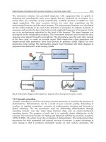
Recent manufacturing industries face various problems caused by the shorter product life cycle, the
higher demand for cost and quality, the more diversified customer needs and so on. In this situation, it
is very important to shorten the lead-time of the manufacturing system construction. Therefore, the
manufacturing simulation has been watched with keen interest. However it is used only for the design
stage of the construction. It is not useful for the implementation stage because of a proprietary
simulation language, a complex modelling, etc. Our goal is to develop a simulation environment
which can be used easily throughout the manufacturing system life cycle. Our approach is based on a
distributed architecture, ORiN and HLA. This simulation environment is composed of some
manufacturing simulators, real FA devices in the factory, its emulators and so on. By distributing them
into one simulation environment on the network, a large-scale simulation and a highly accurate
simulation are achieved.
KEYWORDS
Manufacturing systems, Distributed simulation, Virtual factory, ORiN, HLA
INTRODUCTION
Manufacturing simulations are very important to shorten the lead-time of the manufacturing system
construction. However, the manufacturing system simulator is not useful at an implementation stage.
One of the main reasons is that the simulation models which are made at the design stage cannot be
reused at the implementation stage. Therefore, a virtual factory at the design stage and a real factory at
the implementation stage cannot be combined efficiently in the system development process.
To solve this problem, current simulators are trying to integrate many functions into themselves. For
instance, some robot simulators have the function to convert the simulation language to the
262
Ch53-I044963.fm Page 262 Tuesday, August 1, 2006 4:09 PM
Ch53-I044963.fm Page 262 Tuesday, August 1, 2006 4:09 PM
262
proprietary robot language. However it is hard to integrate all functions required in a real factory,
because the real factory is composed of many kinds of devices. This approach is confronted with a lot
of problems. To cope with the problem, we made conceptual change from INTEGRATION to
DISTRIBUTION.
In this paper, we propose a simulation environment which is integrating the real devices into the
manufacturing simulation systems on the network. This environment is realized as a distributed real
simulation system. The system is composed of ORiN system, soft-wiring system, production cell
simulator, ORiN-HLA gateway and so on. By using this system, manufacturing system developers are
able to use the same simulation model consistently from the design stage to the implementation stage.
BASIC CONCEPT
The procedure for developing a manufacturing system is commonly based on the waterfall model to
reduce a waste of loop-back and re-doing. But still there are many loop-backs on each process. It is
difficult to shorten the manufacturing system development time without reducing the loop-backs.
Therefore, it is necessary for development time reduction to reduce the "loop frequency" and/or to
shorten the "loop time".
To reduce the loop frequency, the upper-layer design process should be highly accurate. To achieve
this goal, the FA programming task in the simulation environment is indispensable. However, this
causes increase in modelling cost and deterioration of cost-effectiveness. The simulation is not usually
used at the implementation stage for these reasons.
As a solution of this problem, we propose an architecture that enables diverting the simulation
program to the real device in the implementation stage. The point is to use the same model throughout
the manufacturing system life cycle. This means that an implementation task is to embody the exactly
same model as the real devices. And this leads to the wide-use of the simulator at the implementation
stage. As a result, this also leads to shorter average loop time because of the easier loop back in the
simulation.
However, it is easy to imagine the difficulty of creating the simulation environment which is usable in
all stages of the manufacturing system construction. The difficulty originates from the fact that the
production system is composed of quite a lot of FA devices. Moreover the user programs of those
devices are described not in a simulation language but in a ladder language or a robot language, etc.
Therefore, we propose architecture of using a real FA device in one simulation environment. By using
actual ladder programs or robot programs in the simulation, the simulation accuracy can be improved,
and those programs can be reused at the implementation stage.
To achieve this simulation environment, it is necessary to realize the following four functions.
1) Function to abstract a wide variety of FA devices.
2) Function to absorb the differences between the abstracted devices and the real devices.
3) Function to connect the abstracted devices logically.
4) Function to simulate the mechanical motion by the signal from the abstracted device.
In addition, to execute a manufacturing cell simulation in the real production environment such as the
production order patterns, it is necessary to make an interaction with the upper-layer simulators such
as a production line simulator. Therefore the following two functions are also required.
5) Function to exchange data between the cell simulator and the upper-layer production simulators.
6) Function to manage the logical time and the synchronization between simulators.
263
Ch53-I044963.fm Page 263 Tuesday, August 1, 2006 4:09 PM
Ch53-I044963.fm Page 263 Tuesday, August
1,
2006
4:09 PM
263
SYSTEM OVERVIEW
In
the
above-mentioned
six
functions,
the
function
1) and 2) are
very important functions.
To
realize
them,
we
developed "Open Resource interface
for the
Network, ORiN" [Inukai
T. and
Sakakibara
S.
(2004)].
ORiN
is the
base system
of the
following
two
sub-systems, "Soft-wiring system"
and
"Cell
Simulator". These systems
are
providing function
3) and 4)
respectively.
To accomplish
the
distributed simulation environment such
as 5) and 6), we use
"High Level
Architecture,
HLA
[Hibino
H. &
Fukuda
Y.
(2002)].
By
using
HLA, the
synchronization
and the
logical time management between simulators
can be
achieved. Figure
1
shows
our
system overview
of
a distributed real simulation environment [Inukai
T.,
Hibino
H. and
Fukuda
Y.
(2004)].
Distributed Real Simulation
- Hybrid Simulation
-
Real Simulation Environment
Function's
^
[2] Cell Simulator
- Mechanical Design
- Geometric Programming
[1
]
Soft-wiring System
[\
-
Electncal Desigri \
Function
4
Distributed Simulation Environment
Figure
1:
Distributed real simulation environment
ORiN
is a
software interface
for FA
devices
and the
applications.
A
real
FA
device
is
abstracted
and is
indirectly accessed through
the
ORiN platform. Therefore
the FA
applications
on
ORiN access
not a
real device
but an
abstracted device.
In
short, ORiN
can
absorb
the
differences
of FA
devices.
Therefore ORiN applications
are
executable both
in a
real factory
and a
virtual factory.
[1] "Soft-wiring system" provides
the
function
to
connect abstracted device logically.
By
using this
system,
the
information stored
in I/O and
variable
of FA
devices
can be
easily
and
intelligently
transferred
to the
other
FA
devices. Moreover different from conventional simulation system, this
system
can
connect
not
only emulators,
but
also emulator
and
real device.
In
other words,
the
client
program need
not
distinguish whether
the
supplied data
is
from
a
real device
or
from
its
emulator.
The
difference
is
completely encapsulated.
[2] "Cell simulator"
can
provide
the
function
to
imitate mechanical motion
in
accordance with
the
signals from
the
soft-wiring system.
The
mechanical behaviours
are
represented
by
two-dimensional
tree structure,
and its
node represents
a
simple motion. Complex motions
are
defined
as a
combination
of simple node.
By
using this simulator, end-user
can
easily define
the
motion
of
production cell.
[3] Synchronization mechanism
and
logical time management mechanism
are
very important
to
achieve
the
seamless communication between simulators.
The
functions
are
provided
by HLA and
ORiN-HLA gateway.
The
upper-layer simulators connected
to HLA can
retrieve
the
information
of a
real device through
the
gateway,
and
vice versa.
264
Ch53-I044963.fm Page 264 Tuesday, August 1, 2006 4:09 PM
Ch53-I044963.fm Page 264 Tuesday, August 1, 2006 4:09 PM
264
A CASE STUDY
A system shown in Figure 2 consists of a cell simulator, a PLC emulator, a real robot device, and a
real bar-code reader, etc. By reading the task instruction from a KANBAN with bar-code reader, a
sequence of tasks is performed.
End-users can not only make a program in ladder and/or robot language, but also check a mechanical
motion and a cycle time, etc. in a distributed real simulation environment. Therefore, compared with
the stressful confirmation task in the real world, the user's load was much reduced.
•» * •
•^•••.^ Cell Simulator [i ,
Real <r-» Virtual
Figure 2: A case study of cell simulation
CONCLUSION
In this paper, we proposed a distributed real simulation environment which composed of ORiN system,
soft-wiring system, cell simulation system and ORiN-HLA gateway. By using this simulation
environment, manufacturing system developers are able to use the same simulation model consistently
from a design stage to an implementation stage. A large-scale simulation and a highly accurate
simulation are also achieved. Consequently end-users can perform a lot of tasks in the simulation.
REFERENCES
Hibino H., Fukuda Y. (2002). Manufacturing Adapter of Distributed Simulation Systems Using HLA,
Proc.
of the 2002 Winter Simulation Conference, pp.1099-1109.
Inukai T., Sakakibara S. (2004). Impact of Open FA System on Automobile Manufacturing, journal of
Society of Automotive Engineers of Japan, (in Japanese), vol. 58, No. 5.
Inukai T., Hibino H., Fukuda Y. (2004). The Gateway of Real Factory and Virtual Factory using
ORiN and HLA, Proc. of the 5th International Conference on Machine Automation.
265
Ch54-I044963.fm Page 265 Thursday, July 27, 2006 8:16 AM
Ch54-I044963.fm Page 265 Thursday, July 27, 2006 8:16 AM
265
OBJECT-ORIENTED EMBEDDED SYSTEM DEVELOPMENT
METHOD FOR EASY AND FAST PROTOTYPING
T. Vallius, J. Haverinen and J. Roning
Computer Engineering Laboratory, Department of Electrical Engineering
University of Oulu
P.O.
Box 4500
FIN-90014 Oulu, Finland
ABSTRACT
Traditionally, embedded system design requires a considerable amount of expertise, time and money.
This complicates the testing of new research results in robotics with real embedded systems, which
would be necessary to bring the results into real use. We are studying an easy and fast embedded
system development method that enables people without special skills in electronics or embedded
systems to create such systems. We hope that this method will ultimately enable utilization of
electronics also in research domains where electronics skills are usually not available. In this paper, we
present an embedded object based architecture, and the ideology of fitting this architecture into the
common object-oriented methods used in software development. We also describe its application to
combined software and hardware entities. This paper concentrates on explaining the ideology and
architecture of this approach.
KEYWORDS
Object-oriented, embedded systems, embedded object, easy, fast, architecture
INTRODUCTION
Motivation
In academic research involving embedded systems (for example in robotics), research on new ideas
usually proceeds as follows: the researcher gets an idea and formulates a hypothesis about it. A model
is created to examine the hypothesis. The model is then simulated and modified iteratively several
times.
Finally, the results are tested in a real embedded system, and depending on the results, the
researcher may have to return to one of the previous phases again. Sometimes there exists a significant
threshold to real hardware tests. This is because the actual process of building a device to test research
results in practice requires a completely new project, another people, lots of expertise, and more time
266
Ch54-I044963.fm Page 266 Thursday, July 27, 2006 8:16 AM
Ch54-I044963.fm Page 266 Thursday, July 27, 2006 8:16 AM
266
and funding. Tests with real hardware are still often necessary in order to bring research innovations
into common use as affordable consumer devices.
We are trying to find out how the creation of an embedded system could be made both affordable and
maximally easy, so that the building would not require much expertise in electronics (see the analogy
with the PropertyService idea of Maenpaa,Tikanmaki, Riekki & Roning (2004), which enables a non-
robotics expert to use robots in research). Thus, different research results in robotics could be tested by
the researchers themselves easily in a real embedded system. However, the research is not restricted to
robotics, but we try to generalize the results to apply to any research involving embedded systems. We
hope that this research will ultimately expand the utilization of electronics also to non-technical areas
of science, thus giving totally new possibilities for non-technical research.
Our approach
For software development there are many high level languages available, which enable one to create
new software both easily and quickly. One example of them is Microsoft Visual Basic. The ease of use
is obtained mostly by an object-oriented approach, visual aids, and a vast amount of ready-made
lower-level code. For embedded systems there is not such a high level possibility to create new
systems. For hardware development, there are some design methods available, such as Grimpe and
Oppenheimer(2001); Kumar et al (1994); Nebel and Schumacher (1996), which in spite of being
modular or object-oriented require a lot of expertise in electronics. For embedded software, there also
are object-oriented design methods available, some of them even quite innovative, for example Awad,
Kuusela and Ziegler (1996) and Object oriented programmable integrated circuits (OOPIC,
). Object-oriented embedded system development, which covers both software
and hardware design, has been studied by Edwards and Green (2000) in the MOOSE method. Still, the
difficulty level of creating an embedded system continues to be very high compared to many high-
level software development tools. At the other end, there are the robotics system sets by LEGO, which
contain a very easy-to-use user interface and a possibility for fast development of hardware (with Lego
bricks), but due to tightly restricted system, they have limited suitability for testing research results or
creating anything but simple systems.
We have studied how the high-level software language techniques could be applied to the process of
developing an embedded system. We propose an architecture and a development method for embedded
systems that is something between LEGO robotics and extended MOOSE, enabling easy building of
object oriented embedded systems with minimal limitations.
HARDWARE MODEL FOR AN OBJECT-ORIENTED EMBEDDED SYSTEM
DEVELOPMENT METHOD
Introduction
Our method is based on small embedded objects called Atomi-objects. Embedded object means that
the Atomi is an object in both software and hardware (embedded system) aspect. Atomis are small
electronic boards that contain some sensor circuits, actuator drivers, or other functionality. The
software of an Atomi resembles an Automation object (ActiveX Control) by Microsoft. It has
properties, methods, and events that correspond to the physical functionality of the Atomi. In other
words, one can set different properties of an Atomi (such as intensity of a light), run methods (such as
a sequence of positions for a servo), and set an Atomi to respond to events (for example, when heat is
below the threshold in a temperature sensor Atomi, the switch property of a heater Atomi is turned on).
Atomi boards can be stacked together, and they interconnect through a simple field bus that is
extended with a common voltage supply line (see Figure 1). Each board contains a microcontroller unit
267
Servo control object
AD-conversions object
Device main control object
Field bus
Servo
connectors
Sensor
connectors
Simple device
Ch54-I044963.fm Page 267 Thursday, July 27, 2006 8:16 AM
Ch54-I044963.fm Page 267 Thursday, July 27, 2006 8:16 AM
267
(MCU). In other words, the physical architecture is a regular field bus device network, where the
Atomis are the nodes of the bus, but which is extended towards object-oriented thinking as combined
software and hardware objects, and implemented in a small physical scale.
Field bus Simple device
7V— Devic e main control object
A-Servo control object
Servo •'
connectors
I- AD-conversions object
Figure 1 Device built with embedded objects i.e. Atomis
Object-oriented thinking
The advantages of object-oriented techniques (OOT) for software are well known (Booch, 1991,
Yourdon, 1994, Martin and Odell, 1992). Many of them apply directly to hardware or an embedded
system, such as maintainability, reusability, stability, reliability, faster designing, and extensibility. In
our case, one of the main reasons for using object-oriented technology is the goal of making an easy,
high-level method to create embedded systems. We consider Atomi as combined software and
hardware object: each Atomi contains its own properties, events, and methods, which are related to
each Atomi's hardware functionalities. As the benefits of the OOT are achieved via some fundamental
elements, such as modularity, encapsulation, abstraction, hierarchy, inheritance, and concurrency, it is
relevant to study how they can be realized in Atomis.
Atomis realize modularity, encapsulation and concurrency naturally via their modular architecture.
Modularity is important element for the high-level development goal, since it enables the use of library
objects i.e. Atomis with ready-made low-level code and hardware. The idea of encapsulation is that the
internal data is hidden from the other objects, and only accessible via specific methods. Since the
software of an Atomi corresponds directly to the hardware, and Atomis are accessible only through the
field bus interface, this realizes naturally. Concurrency means the handling of different events
simultaneously. In the Atomi context it is realized through the multiprocessor architecture.
Abstraction and hierarchy are combined through inheritance. Abstraction means presenting the
essential characteristics of an object that distinguishes it from other types of objects, and hierarchy
means ranking or ordering these abstractions. Inheritance represents a hierarchy of abstractions, in
which a subclass (child) inherits from one or more superclasses (parents) (Booch, 1991). In the Atomi
architecture, inheritance is realized at two levels. A new object inheriting another object or objects can
be realized by just stacking the objects, i.e. Atomis, together and writing new software for the new
child object. This we call high-level inheritance (see Figure 2). Here, the child object controls the
parent objects, while the interfacing to others takes place via the interface of the new child object. This
procedure implements the inheritance of the parents as public class members, since others can access
them directly because they are all on the same bus. However, the new child object can also have two
interfaces (field bus interfaces and software protocol stacks) and thus implement the inheritance as
private class members by attaching objects into the second bus, which is separated from the common
bus.
268
public class members private class members
New child Atomi
Parent Atomi 1
Parent Atomi 2
Other Atomi 1
Parent Atomi 3
Parent Atomi 4
public bus
private bus
Other Atomi 2
Ch54-I044963.fm Page 268 Thursday, July 27, 2006 8:16 AM
Ch54-I044963.fm Page 268 Thursday, July 27, 2006 8:16 AM
268
public bus | Other Atomi 2 |
private bus
\
I
O
th
er Atomi 1
NT "
|
child Atomi |
Parent Atomi 3 Parent Atomi 1
• " • •
| Parent Atomi 4 11 Parent Atomi 2 |.
private class members public class members
Figure 2 High-level inheritance
Low level inheritance is in question when a completely new Atomi is to be created. In this case,
inheritance is realized as a template or base Atomi object. A template Atomi object, which can also be
thought of as a generalized abstraction of an Atomi, contains the schematic and layout drawings of an
Atomi consisting of the common hardware for the basic Atomi interface. Correspondingly, there is a
software template for operating this basic hardware. Thus, inheriting the base Atomi object to create a
new object is realized as copying the templates and adding the new components into half-ready
schematics and PCB layout and the corresponding control functions for the software. In our test
system, the common hardware means an MCU and connectors, and the software means a field bus
code with some interface-related code. The low-level inheritance is very important for the flexibility of
this architecture, as it enables fully customized Atomis to be created. It also presents a problem for the
ease of the Atomi system, as it requires hardware development and hence also some skills and
resources in electronics. However, there is still a significant advantage over designing a whole new
system, because large parts of the design process for the new Atomi are available as templates.
The characteristics of OOT include the idea of increasing complexity by creating new objects out of a
set of other objects. This realizes in the high level inheritance, and it can be realized also by normal
aggregation, i.e. by creating a new object that includes other objects. In the physical Atomi
architecture however, both inheritance and aggregation realizes similarly, and there is thus not much
difference. Since new objects can be created by inheriting/aggregating objects that already have
inherited/aggregated objects, the complexity of objects and hence the device can be increased as
needed. However, physical restrictions may become a problem at some point. The major restricting
factor for object-oriented architecture is the field bus. The field bus capacity defines the real-time
capabilities of the system and the maximum number of objects in one bus. However, the architecture
can be realized using almost any field bus. Thus, larger systems may use faster buses. Another
restricting factor could be the processing power of the MCU, but as the encapsulation suggests, each
object can implement its functions hidden from others. Thus, the objects can use any MCU that meets
the processing requirements of its functions, as long as it just implements its interface.
DISCUSSION
Towards high-level development
The object-oriented embedded system method has been tested in some devices (Vallius & Roning,
2005a, Vallius & Roning, 2005b, Tikanmaki, Vallius & Roning, 2004) and it is found to be functional.
The object-oriented embedded system method brings the development process one step closer to a
high-level software programming language: an embedded system can be built by stacking up suitable
embedded objects and then just adding a control code to a specific control object. In other words, the
269
Ch54-I044963.fm Page 269 Thursday, July 27, 2006 8:16 AM
Ch54-I044963.fm Page 269 Thursday, July 27, 2006 8:16 AM
269
lower-level software and hardware are available as objects, and only the high-level control must be
developed. This corresponds to high-level software development tools, by which you may create new
applications by selecting appropriate software objects from a library and use them with you own
control code.
To create a new device, common object-oriented design methods can be used to break up the basic
functionality into smaller modules. Usually, the modular diagram of the designed system consists of
some functional modules and a control module. In that diagram, the modules correspond directly to
Atomi objects, which gives us interesting options. One option is that the control module is a computer.
Software creation for a computer is easy because of the great processing power and easy debugging. In
the computer one can also use high-level software languages, which makes code generation easy.
Another option is to use an Atomi object to control the other objects. If the system is designed
properly, the control module could simply contain the mainQ-function that controls the other Atomi
objects. In many software development methods, the control module usually contains a state machine,
which controls the other modules. Since a state machine is a very trivial code structure, it is easy to
program with almost any programming language. To make it easier, there can also be template state
machine code structures, where the user fills in the states and transitions, compiles the code and inserts
it into the control module. A graphical state machine editor can be used to make its programming as
easy as possible. The control module could even contain a neural network Atomi object. With this
approach, some advanced learning methods could be used to teach the device to perform the desired
operations. The device could also work without a separate control module. Since all modules can
produce events, these events can be set to trigger actions on other modules and thus make the whole
device work reactively. These options require still more research and will be considered later.
Cost
If devices designed with this architecture were to be mass-produced, the costs would most likely
exceed the cost of an embedded system made with a traditional architecture because of several extra
components. On the other hand, if only a few devices were needed of one system, this architecture
could be more cost-effective. Depending on the suitability of ready-made modules, the speed of
producing a complete device would be faster with the object-oriented embedded system method. The
biggest time advantage would most likely come at the debugging phase of the hardware and the
software. The hardware and software of a system made with traditional methods or with object-
oriented methods, where the objects do not remain independent in the resulting hardware, and the
processes do not run in independent processors in the resulting software, the mixing of new hardware
and software or existing library objects can cause interference to existing objects. Since the embedded
object method is completely encapsulated in software and almost completely in hardware, the risk of
malfunctions in library objects is likely to be reduced.
The possibility of high-level system development may also bring cost benefits in the form of a reduced
need for expertise. In situations where needed embedded objects are already available, a non-
hardware-oriented person is able to create a simple embedded system, provided that the needed objects
are available, and no custom objects are needed. Luckily, many sensors and actuators uses common
interfaces, such as analog voltage output, serial port, i2c bus, SPI, pulse width modulation, or
8-bit
data bus. Thus, with only a few Atomi objects, considerably many kinds of peripherals can be
controlled by merely choosing suitable connectors for them.
Success in creating a high-level language embedded system creation method could also inspire IC
manufacturers to develop an Atomi-like packaging method for integrated circuits. This kind of a trend
can already be seen in the electronics industry, as more integrated and easy-to-use modules come to
the market all the time. Only the common interface is missing, and that is what makes Atomi objects
feasible.
270
Ch54-I044963.fm Page 270 Thursday, July 27, 2006 8:16 AM
Ch54-I044963.fm Page 270 Thursday, July 27, 2006 8:16 AM
270
CONCLUSION AND FUTURE DEVELOPMENT
We have presented an embedded object based architecture and the ideology of fitting this architecture
into the common object-oriented methods used in software development. We have applied it with
combined software and hardware entities called Atomi-objects and evaluated the pros and cons of such
an architecture and design method. The method has also been tested in some devices. This study serves
as a basis for further research on high-level development of embedded systems. Some further research
will be made towards that goal: to make the Atomi method most feasible, the most common and
general Atomi objects should be readily available. The methods for mapping existing design methods
to the Atomi architecture will be studied.
ACKNOWLEDGMENTS
This work is supported by the Finnish Academy and InfoTech.
REFERENCES
Awad M., Kuusela J. & Ziegler J. (1996). Object-Oriented Technology for Real-Time Systems,
Prentice Hall.
Booch G. (1991). Object oriented design with applications, Benjamin/Cummings.
Edwards M. & Green P. (2000). An Object Oriented Design Method for Reconfigurable Computing
Systems, Design, Automation and Test in Europe Conference and Exhibition 2000, proceedings. 27-
30 March 2000, Page(s): 692 -696.
Grimpe E. & Oppenheimer F. (2001). Object-oriented high level synthesis based on SystemC,
Electronics, Circuits and Systems, 2001. ICECS 2001. The 8th IEEE International Conference on,
Volume: 1, 2-5 Sept. 2001, Page(s): 529 -534
vol.1 .
Kumar S., Aylor J.H., Johnson B.W. & Wulf W.A. (1994). Object-oriented techniques in hardware
design, Computer, Volume 27 Issue 6, June 1994, Page(s): 64 -70.
Martin J. & Odell JJ. (1992). Object-Oriented Analysis and Design, Prentice Hall.
Maenpaa T., Tikanmaki A., Riekki J. & Roning J. (2004). A Distributed Architecture for Executing
Complex Tasks with Multiple Robots, IEEE 2004 ICRA, International Conference on Robotics and
Automation, proceedings. Apr 26- May 1, New Orleans, LA, USA.
Nebel W. & Schumacher G. (1996). Object-oriented Hardware Modelling - Where to Apply and What
are the Objects'?, Design Automation Conference, 1996, with EURO-VHDL '96 and Exhibition,
Proceedings EURO-DAC '96, European, proceedings. 16-20 Sept. 1996, Page(s): 428 -433.
Tikanmaki A., Vallius T., and Roning J. (2004). Qutie - Modular methods for building complex
mechatronics systems, International Conference on Machine Automation (ICMA2004), proceedings.
Nov 24 - Nov 26, 2004, Osaka, Japan.
Vallius T. & Roning J. (2005a). Implementation of the "Embedded Object" Concept and an Example
of Using it with UML, The 6th IEEE International Symposium on Computational Intelligence in
Robotics and Automation, proceedings, Jun 27 - Jul 30, 2005, Helsinki University of technology,
Finland.
Vallius T. & Roning J. (2005b). Embedded Object Concept with a Telepresence Robot System, SPIE
Optics East 2005, proceedings. 23-26 October 2005, Boston Marriott Copley Place, Boston,
Massachusetts, USA.
Yourdon E. (1994). Object-Oriented System Design: An Integrated Approach, Prentice Hall.
271
Ch55-I044963.fm Page 271 Tuesday, August 1, 2006 9:39 PM
Ch55-I044963.fm Page 271 Tuesday, August
1,
2006 9:39
PM
111
INTEGRATED CONSTRUCTION PROCESS
MANAGEMENT SYSTEM
Masayuki Takata
1
, Eiji Arai
2
and
Junichi Yagi
3
1 Information Processing Center,
The
Univ.
of
Electro-Communications
Chofu-shi, Tokyo 182-8585, Japan
2 Department
of
Manufacturing Science, Osaka University
Suita-shi, Osaka 565-0871, Japan
3 Institute
of
Technology, Shimizu Corporation
Koto-ku, Tokyo 135-8530, Japan
ABSTRACT
This paper describes
an
implementation
of an
Integrated Construction Process Management
Sys-
tem, which includes both manufacturing process management features
for
building parts
and
also
construction progress management features
at
construction site.
To
monitor
the
flow
of the
build-
ing parts, RFIDs
are
stuck
to all of the
parts
to be
managed,
and
several checkpoints, which
we named "gates",
are
introduced within
the
coherent process through part-manufacturing plant
line,
logistic processes
and
building construction processes.
By
means
of
this, building parts
can
be tracked certainly,
and
anyone
can
know
the
status
and the
location
of
building parts
at
that
instant.
KEYWORDS
integrated process management system, part-manufacturing process management, building
con-
struction process management, intensive data management system
1 INTRODUCTION
This paper describes
an
implementation
of
the integrated construction process management system,
which includes manufacturing process management features
for
building materials,
and
construc-
tion process management features
at
construction site. Recently, RFIDs
are
getting popular
in
logistics
and
manufacturing industries.
The
process management system
for
building construc-
tion
and
building materials manufacturing must cover these
two
aspects,
and the use of
RFIDs
in
construction industries will make
the
trace-ability
of the
building materials more accurate.
The
system
we
aimed enables efficient project management
and
diminish
the
loss
in the
construction,
by providing
all
information
of the
both material manufacturing
and
building construction
to all
of material designing, material manufacturing, building designing
and
building construction sites.
272
Ch55-I044963.fm Page 272 Tuesday, August 1, 2006 9:39 PM
Ch55-I044963.fm Page
272
Tuesday, August
1,
2006
9:39 PM
272
2 APPROACH
In this implementation,
we
aimed
to
confirm that
the
system integrity
on the
whole.
In
order
to
make
its
information processing simple,
the
process management engine uses only typical durations
to process each step
in the
manufacturing materials
or
installing them,
and the
bills
of
materials.
In order
to
trace WIPs (Work
In
Processes),
we
installed several checkpoints representing bound-
aries
of
logical activities, which
we
named "gates",
in the
process through material-manufacturing
and building-construction.
On
WIPs passing these gates, RFIDs
are
read
and
progress reports
are
collected.As
the
WIP's
due
time
for
passing
the
final inspection process gate
is
deduced from
the
overall schedule
of the
construction,
the due
time
for
passing each gates
can be
calculated from
the given final
due
time
and the
typical durations from
one
gate
to the
next.
On the
other hand,
when WIPs pass each gates,
the
estimated time
for
passing following gates
can be
calculated.
In these
way, for
each building materials types,
we can
obtain both
due
time
for all
demands
and
for
all
gates,
and
actual
or
estimated time
for all
WIPs.
By
associating each demands
and
each
WIPs
in the
order
of
time passing
a
certain gate
for
each materials type,
we
carry
out the
allocation
of demands
and
WIPs.
In the
case
of due
time
of
allocated demands
is
earlier than estimated time
of associated
WIP
passing
by, we
assume that tardiness
is
expected
and
some action
is
required.
3 THE IMPLEMENTATION
3.1 Gates
In order
to
trace WIPs,
we
have
set up
nine gates within both material-manufacturing
and
building-
construction processes,
as
follows;
(I)
Design approved,
(2)
Ordering
raw
material,
(3)
Start
pro-
cessing,
(4)
Assembling,
(5)
Shipping
out
from
the
manufacturing plant,
(6)
Carrying into
the
construction site,
(7)
Distributing within
the
construction site,
(8)
Installing building material
in
the building,
(9)
Final inspection.
It is
easy
for the
system
to
change
the
number
of
gates,
to
change typical durations from gate
to the
next.
When
the
WIPs pass gates, following processes
are
took place.
(1)
Reading RFID
on the WIP, (2)
Converting
to the WIP
identifier,
(3)
Logging
the
time passing
the
gate,
(4)
Logging
the
physical
position
of WIP, (5)
Logging
the
result
of the
post-process testing. These data
are
accumulated
within
an
actual achievement database resides
in the
shared data space, described later.
3.2 Tracking Works with RFIDs
At each gate,
the
system gathers actual achievement information
by
means
of
RFIDs.
In
this
implementation,
we
used read-only type RFIDs with
128 bit
length identifiers. Generally speaking,
as each building materials consists
of
multiple parts which
are
manufactured independently
in the
manufacturing line, single building material
may
contain multiple RFIDs
in it. On
reading RFIDs
of
a
building material, some RFIDs
may
respond
and
some
may not, but the
tracking engine should
handle these information properly.
In
some cases,
an
assembled
WIP may be
dis-assembled
and
re-assembled find much more matching combination.
So,
the
tracking engine should have following features.
1.
Identifying
the WIP
from partial RFIDs information.
2.
Keeping RFID identifiers
of all
parts consisting
the WIP.
3.
Keeping tree-structured information including assembling order
and
part structure,
for the
case
of dis-assembling
and
re-assembling.
273
Ch55-I044963.fm Page 273 Tuesday, August 1, 2006 9:39 PM
Ch55-I044963.fm Page 273 Tuesday, August 1, 2006 9:39 PM
273
Furthermore, it is expected that reading some particular RFIDs instead of entering some infor-
mation manually, such as operator name, physical location of the work-cell, and others. So, the
tracking system can judge whether given identifier represents some WIP or process equipment.
3.3 Allocation
In this implementation, we use simple algorithm described in the Section 2 to allocate demand
to corresponding WIP. The basic data, which are the typical durations from one gate to the next
or previous gate and the bills of materials, are given and stored in the shared data space among
multiple processing agents, described later. The typical durations for due date deduction may
differ from those for calculating estimated times for following gates. Both durations are defined
for all product types, but the users can define other values to override them for respective types.
We named the lists of same type WIPs, arranged in the order of expected time passing a predefined
gate,
as "preceding list." In other hand, we named the list of same type demand, arranged in the
order of due time at a predefined gate, as "priority list." Their priority is defined only by the due
time order, and we ignore any other aspects.demands.
All demands and WIPs are processed in building material type by type, and in the case of the
material type made from multiple parts, the demands of those parts is newly created at the gate
at which those parts are assembled together, according to the bills of materials. The due time of
the parts are given from the due time of the assembled WIP at the same gate. The estimated time
of a WIP to pass the assembling gate is calculated as the latest one of those times of its parts.
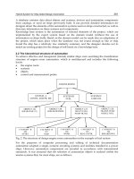
3.4 User Interface
In this subsection, we describe the user interface screens implemented. The user interface of this
system was developed as the application of WWW (World Wide Web) system, in order to make
them accessible from not only desk-top computer systems but also portable data terminals.
Figure 1 shows the status display for one particular association of the demand and the WIP,
including the parts which demands and WIPs consists of. In each table entry, the upper row
contains date information in the format of YYYYMMDD, and the lower one contains time in
the format of HHMMSS. The table entries show the due time of the demand for that gate with
Hie Edit
T Bac k
UnitTr
IJNITODO l
IAA
JOmUrrtOO Q
^^
IF7-U
Vie w
Go
Communeato r
ard Reloa d Him e Searc h Guid e
Pr
ee — Unit Identifier: UNITOOO1
1 Design
[20031030
11 210000
;
1
:
[20031030
.[ 210000
120031025
3 120000
20031115
210000
30031110
120000
20031115
210000
20031109
120000
Proc.
|
20:31123
21000: i
3:0:31123"
12000:|
20:31123
;iooo:
50:31122
12000:|
Gates-
Assem. Sk^Ort
gy
-| i-
______
210000 i 210000
c:,,•-;•;;:, •»
Hi Ss.ril, s
•'"•• •'
r
•;
"I .
" „
20031130
;
20031201 2
21:000 i osoooo
,=cooo; mm,
0031127[20031123[20031130 [2003:20112
21000QJ 2100Q0
0031127 20031129
120000 12
21:000 ! 050000
Install Imaged
150000: 180000
^'
x
^!
x
".
____ _
15000 0
i
-»»; -
— • •
0031201]~
lSOOOO j
•-I
H'lp |
4
Figure 1: Due time to passing gates and estimated time passing followings
274
Ch55-I044963.fm Page 274 Tuesday, August 1, 2006 9:39 PM
Ch55-I044963.fm Page
274
Tuesday, August
1,
2006
9:39 PM
274
•type List — Type Identifier: AW1
"type List — "Type Identifier: AW1
Figure
2:
Status display
for all
works
of
specified building material type
J
Figure
3:
Status after changing
due
time
while background color, show
the
actual achievement time
of the WIP to
pass
the
gate with green
background,
and the
estimated time
of the WIP to
pass
the
gate with blue background.
The red
characters show
the
tardiness expected.
The
neighboring entries consisting upper demand line
and
lower
WIP
line show
the
allocated pair.
As the
allocation
is
subject
to
change,
the
display contents
change when
due
dates
are
changed
or WIP
passes
new
gate.
Figure
2
shows
the
status display
for one
particular type
of
building materials, including
the
parts which demands
and
WIPs consists
of.
This example shows that
two
building materials
are
currently under processing,
and one WIP
recovered
its
tardiness
at the
first gate,
by
shorten
the
duration
for
processing from
the
first gate
to the
second,
but
another
WIP has
delayed
at the
last
gate
it
passed
and
tardiness
at the
gate
for the
final inspection
is
expected.
In
order
to
recover
such situations,
one may try to
shorten
the
duration from
the
gate
to the
next,
or may
postpone
the
due
time
for the
final inspection
of the
building materials installation.
Figure
3
shows
the
case
of
postponing
the due
time
of the
final inspection
of the
unit with unit-ID
UNIT0001
for
four days.
As the
result,
the due
time
of the
unit UNIT0001
and
that
of the
unit
UNIT0002
are
reversed,
and the
parts
set
which
are
going
to be
used
for
those units
are
exchanged.
4
THE
INFRASTRUCTURE SYSTEM
In this study,
we
used
the
system named "Glue Logic"
[1,2] as the
infrastructure
to
support
multiple-agent processing system.
The
Glue Logic, which
is
developed
by the
Univ.
of
Electro-
Communications, includes
the
active database
and the
network transparent programming environ-
ment,
and
supports data processing
in the
event driven programming paradigm. Figure
4
shows
the overall structure implemented using
the
Glue Logic infrastructure system.
The active database
is a
subclass
of the
database systems,
of
which databases have
an
abilities
to behave when
it
finds some changes
of its
contents, without waiting
for
external actions.
The
change
of the
contents includes;
(1)
when data
is
changed,
and (2)
when some relations
are
formed.
On
the
other hand,
the
behavior executed
on
these incidents includes;
(1)
changing contents
of the
275
Ch55-I044963.fm Page 275 Tuesday, August 1, 2006 9:39 PM
Ch55-I044963.fm Page 275 Tuesday, August 1, 2006 9:39 PM
275
PDA
Figure 4: Overall Structure of the Implementation
database, (2) calculating certain expression and store the result inside and (3) sending message to
some client agents.
The Glue Logic is designed to make building manufacturing work-cell control systems easy and
flexible, and also coordinates agents by means of followings;
• Providing field of coordination
• Implementing shared data space among agents
• Virtualizing agents within the shared data name space
• Controlling message passing among agents
• Implementing mutual execution primitives
• Prompting agents to start processing
• Adapting control systems to real-time and network processing environment
As the Glue Logic supports event notification and condition monitoring features based on active
database scheme, users can easily build real-time and event-driven application agents, only waiting
for notification messages from the Glue Logic.
Each agents in an application system can be developed concurrently, and can be added, deleted
or changed freely without modifying other existing agents. As the result of these, the Glue Logic
compliant agents are easy to re-use, and the users can build large libraries of application agents.
In this implementation, the flow of its data processing is as follows.
1.
When a WIP reaches a gate, or when a due time of a demand changes, the corresponding
agent is activated via a CGI for the WWW user interface. These agents updates the actual
achievement records for WIPs or the due time requirement records for demands. These records
are kept in the shared data space in the Glue Logic.
2.
When shared data is changed, some messages are sent from Glue Logic to agents which is going
to handle the data items. This time, the agents keeping preceding lists or priority lists are
informed, and update those contents.
3.
When the contents of preceding lists or priority lists are changed, the notification message is
sent to the allocation agent. The allocation agent reads preceding lists and priority lists, and
then makeup associations between demands and WIPs.
5
EVALUATION
We implement whole system on a Sun Netra Tl processor running on Solaris 8 operating system.
Through this implementation, we found following performance considerations.
276
Ch55-I044963.fm Page 276 Tuesday, August 1, 2006 9:39 PM
Ch55-I044963.fm Page 276 Tuesday, August
1,
2006
9:39 PM
276
1.
Re-allocation
of the
demand hardly took place unless
due
time
of
final inspection changed
or
some WIPs pass other preceding WIPs.
2.
In
many cases,
as
there
are
less than tens
of
WIPs concurrently being processed
in the
whole
system, re-allocation
of the
demand takes only
a few
seconds.
In the
case
of
building materials
consisting multiple parts,
as the
multiple re-allocation processes occur,
it may
takes more than
ten seconds.
We used multiple agent support systems
in the
implementation,
in
order
to
ease future extension
of functionality. From
the
view point
of the
system extend-ability,
we
found followings.
1.
All
information
on the
actual process achievements
are
kept within
a
database. This makes
any
other agents being able
to
utilize these data
for
processing
and
user interface purpose within
a
few seconds, such
as
status display systems
and
e-mail sender programs.
2.
It
seems
to be
appropriate that
the
conversion from
the
identifier
of
RFID
to
building material
identifier should
be
done
by
specialized subsystem
in the
management system. There
may be
many class
of
RFIDs other than expressing WIPs.
In this implementation,
we
introduced some limitations
to
simplify
the
system,
as
follows.
1.
There
is no
problem solving engine
to
minimize cost.
To find best solution
of
re-allocation,
it is
required
to
minimize cost
to
re-distribute building
materials,
or in
some cases
it is
required
to
determine which
WIP to be
scraped. Solving these
problems
may
need massive computational power, because
of the
combinational explosion.
2.
There
is no
clear decision rules
to be
embedded within
the
system.
Some incidents
can be
processed automatically without human interventions,
but
some require
human approvals. There
is no
clear border
and the
best
way
depends
on its
environment.
6
CONCLUSION
Through this implementation described above,
we
found that
the
integrated process management
system including both part-manufacturing
and
building construction
is
feasible enough.
In
this
financial year,
we are now
going
to
carry
out a
field test, applying this system
to the
actual
manufacturing
and
construction sites.
ACKNOWLEDGMENTS
This research activity
has
been carried
out as a
part
of the
Intelligent Manufacturing Systems
(IMS) international research program: "Innovative
and
Intelligent Parts-oriented Construction
(IF7-II)."
We
appreciate
the
kind guidance
of
each members
of
this project.
REFERENCES
[1] Takata
M and
Arai
E.
(2001). Implementation
of a
Layer Structured Control System
on the
"Glue Logic". Global Engineering, Manufacturing
and
Enterprise Networks pp.488-496, Kluwer
Academic Publishers.
[2] Takata
M and
Arai
E.
(2005). Implementation
of a
Data Gathering System with Scalable
Intelligent Control Architecture. KNOWLEDGE
AND
SKILL CHAINS
IN
ENGENEERING
AND MANUFACTURING: Information Infrastructure
in the Era of
Global Communications,
pp.261-268, Springer.
277
Ch56-I044963.fm Page 277 Thursday, July 27, 2006 8:22 AM
Ch56-I044963.fm Page 277 Thursday, July 27, 2006 8:22 AM
277
A ROBOTIZED SYSTEM FOR PROTOTYPE MANUFACTURING
OF CASTINGS AND BILLETS
Mikko Sallinen
1
, Matti Sirvio
2
'VTT Electronics, Kaitovayla 1, 90571 Oulu, Finland
Simtech Systems Inc.oy, Kukkaromaki 6C5, 02770, Espoo, Finland
ABSTRACT
In this paper, we present a new method for manufacturing prototype castings using robot-based
system. The contribution of the paper is new methods and tools for managing very different sizes of
work pieces. The tools helps and assists the designer for manufacturing pieces which are not a
straightforward to program for the robot. The methods are designed for prototype manufacturing
which means lotsize is something between one to ten.
KEYWORDS: robot milling, off-line programming, prototype casting
1.
INTRODUCTION
The models for prototypes of the cast objects has been traditionally made by hands. They are made
by wood and the form has been generated into a sand box. Nowadays, the wooden or plastic models
are made using a milling machine where the first step towards automation has been taken. However,
the disadvantages of the milling machine is the price and flexibility and therefore we have been
taken a new approach to use robot as a milling machine Sirvio et. al. (2002). Robot-based milling
stations have been developed in low intensity over the last number of years. The two main
restrictive reasons for use of robot in milling are the rigidity of industrial robots and the difficulty of
flexible off-line programming. Rigidity of the robot systems is not anymore such a problem like
several years ago. However, in the last years, another problem has been high (or high enough)
absolute accuracy of the robot manipulators.
The machining of moulds or other prototypes has been made so far using a milling machine
Boomenthal (2000). The difficulty of programming 5-axis machining as well as the lack of required
accuracy has been forced to use three to five times expensive milling machine instead of a robot.
The robotic milling that has been done so far has been concentrated on milling on soft materials like
different kind of foams or wood to avoid the problems of rigidity Veergest et. al. (1998). The
machining of large work pieces and path planning for material removing has been studied in Jager
et. al. (2001).
278
Ch56-I044963.fm Page 278 Thursday, July 27, 2006 8:22 AM
Ch56-I044963.fm Page 278 Thursday, July 27, 2006 8:22 AM
278
This paper
is
organized
as
follows:
in
chapter
1 an
introduction
to the
topic
is
given. Chapter
2
describes
the
prototype manufacturing process,
the use of
robot system
is
described
in
chapter
3.
Results from actual tests
are in
chapter
4.
Finally conclusions
are
given
in
chapter
5.
2.
DESCRIPTION
OF
THE PROCESS
The principle
of the
short series production
is
explained
as
follows.
The
geometry
of
the casting
will
be
machined into
the
sand. After machining
and
coating
the
mould,
the
work piece will
be
cast.
Depending
on the
properties
of the
casting, this process
is
repeated until
a
piece with sufficient
qualifications
has
been achieved. This
may
require
one to ten
iteration steps. Numerous castings
that
are
produced
in
small batches, including prototypes
and
spare parts, they will
be
produced
by
substitution
of
the pattern making process with advanced robotics
and
utilization
of a
digital library
created from
a
CAD model, thus economizing
in
terms
of
materials
and
storage space used and time
spent. Moreover, patterns will
be
manufactured
by
using
the
same system
by
only substituting sand
mould with plastic material. This will increase
end
user's productivity over 50%
and
decrease costs
substantially, especially when prototypes
are
developed. From
a
technical point
of
view,
new
products,
of
enhanced shapes will
be
created
in
extremely short times
and in as
many items
as
desired. Finally,
the
milling
and
mould making
can be
totally isolated from
the
foundry
environment,
a
fact that will decrease dust production substantially.
In
figure
1, the
prototype
production could
be
made without pattern making process.
3.
ROBOTIC SYSTEM FOR PROTOTYPE MANUFACTURING
The robot system consists
of CAM
phase, where
the
milling paths
are
generated, off-line
programming phase, where
the
robot programs
are
postprocessed
and
actual running phase where
the milling itself is carried
out.
3.1
CAD
/CAM
In
the
system,
raw
manufacturing paths
are
generated
in
CAM software.
Raw
means here that
no
machine dependent information
is
needed, only information
of
tools.
The
system
is
designed
to be
open such that designer
can use any
commercia l CAD/CAM software
he is
used
to and the
output
is
in
APT
format. Therefore,
the
threshold
of
taking
use of the
proposed technology
is as low as
possible.
In the
CAM phase, user selects
the
general milling parameters such
as
tool contact angle
and deepness
of
milling. These can
be
selected similar way
as
when using milling machine because
3D-CAD
Model
Robotic
Path
Generation
(CAM)
Recycling
of
sand
Grinding
of
the
Sand
Mould
Dust
Removal
Small-Series'
Casting
Pattern
or
Casting
Figure
1.
Foundry process with robotic sand grinding system