MEMS and Microstructures in Aerospace Applications - Robert Osiander et al (Eds) Part 12 pot
Bạn đang xem bản rút gọn của tài liệu. Xem và tải ngay bản đầy đủ của tài liệu tại đây (294.8 KB, 13 trang )
When designs also require high-frequency RF signals, the signals can be
introduced into the package along metal lines passing through the package walls,
or they may be electromagnetically coupled into the package through apertures in
the package walls. Ideally, RF energy is coupled between the system and the
MEMS without any loss in power, but in practice, this is not possible since perfect
conductors and insulators are not available. In addition, power may be lost to
radiation, by reflection from components that are not impedance matched, or
from discontinuities in the transmission lines. The final connection between the
MEMS and the DC and RF lines is usually made with wire bonds; although flip-
chip die attachment and multilayer interconnects using thin dielectric may also be
possible.
12.2 TYPES OF MEMS PACKAGES
Each MEMS application usually requires a new package design to optimize its
performance or to meet the needs of the system. It is possible to loosely group
packages into several categories. Four of these categories are: (1) metal packages,
(2) ceramic packages, (3) thin-film multilayer packages, and (4) plastic packages
are presented below.
12.2.1 METAL PACKAGES
Metal packages are often used for microwave multichip modules and hybrid
circuits because they provide excellent thermal dissipation and excellent
electromagnetic shielding. They can have a large internal volume while still main-
taining mechanical reliability. The package can either use an integrated base and
sidewalls with a lid, or it can have a separate base, sidewalls, and lid. Inside the
package, ceramic substrates or chip carriers are required for use with the feed-
throughs.
The selection of the proper metal can be critical. CuW (10/90), Silvar
1
(a Ni–
Fe alloy) (Semiconductor Packaging Materials, Armonk, NY), CuMo (15/85), and
CuW (15/85) all have good thermal conductivity and a higher CTE than silicon,
which makes them good choices. Kovar
1
(ESPI, Ashland, OR), a Fe–Ni–Co
alloy is also commonly used. All of these materials, in addition to Alloy-42, may
be used for the sidewalls and lid. Cu, Ag, or Au plating of the packages is
commonly done.
Before final assembly, a bake is usually performed to drive out any trapped gas
or moisture. This reduces the onset of corrosion-related failures. During assembly,
the highest temperature-curing epoxies or solders should be used first and subse-
quent processing temperatures should decrease until the final lid seal is done at the
lowest temperature to avoid later steps from damaging earlier steps. Au–Sn is a
commonly used solder that works well when the two materials to be bonded have
similar CTEs. Au–Sn solder joints of materials with a large CTE mismatch are
susceptible to fatigue failures after temperature cycling. The Au–Sn intermetallics
that form tend to be brittle and can accommodate only low amounts of stress.
Osiander / MEMS and microstructures in Aerospace applications DK3181_c012 Final Proof page 272 1.9.2005 9:13pm
272 MEMS and Microstructures in Aerospace Applications
© 2006 by Taylor & Francis Group, LLC
Welding (using lasers to locally heat the joint between the two parts without
raising the temperature of the entire part) is a commonly used alternative to solders.
Regardless of the seal technology, no voids or misalignments can be tolerated since
they can compromise the package hermeticity. Hermeticity can also be affected by
the feedthroughs that are required in metal packages. These feedthroughs are
generally made of glass or ceramic and each method (glass seal or alumina
feedthrough) has its weakness. Glass can crack during handling and thermal cyc-
ling. The conductor exiting through the ceramic feedthrough may not seal properly
due to metallurgical reasons. Generally, these failures are due to processing prob-
lems as the ceramic must be metallized so that the conductor (generally metal) may
be soldered (or brazed) to it.
The metallization process must allow for complete wetting of the conducting
pin to the ceramic. Incomplete wetting can show up as a failure during thermal
cycle testing.
12.2.2 CERAMIC PACKAGES
Ceramic packages have several features that make them especially useful for
microelectronics as well as MEMS. They provide low mass, are easily mass-
produced, and can be low in cost. They can be made hermetic, and can more easily
integrate signal distribution lines and feedthroughs. They can be machined to
perform many different functions. By incorporating multiple layers of ceramics
and interconnect lines, electrical performance of the package can be tailored to meet
design requirements. These types of packages are generally referred to as co-fired
multilayer ceramic packages. Details of the co-fired process are outlined below.
Multilayer ceramic packages also allow reduced size and cost of the total system by
integrating multiple MEMS and/or other components into a single, hermetic pack-
age. These multilayer packages offer significant size and mass reduction over
metal-walled packages. Most of that advantage is derived by the use of three
dimensions instead of two for interconnect lines.
Co-fired ceramic packages are constructed from individual pieces of ceramic in
the ‘‘green’’ or unfired state. These materials are thin, pliable films. During a typical
process, the films are stretched across a frame in a way similar to that used by an
artist to stretch a canvas across a frame. On each layer, metal lines are deposited
using thick-film processing (usually screen printing), and via holes for interlayer
interconnects are drilled or punched. After all of the layers have been fabricated, the
unfired pieces are stacked and aligned using registration holes and laminated
together. Finally, the part is fired at a high temperature. MEMS and possibly
other components are then attached into place (usually organically [epoxy] or
metallurgically [solders]), and wire bonds are made the same as those used for
metal packages.
Several problems can affect the reliability of this package type. First, the green-
state ceramic shrinks during the firing step. The amount of shrinkage is dependent
on the number and position of via holes and wells cut into each layer. Therefore,
different layers may shrink more than others creating stress in the final package.
Osiander / MEMS and microstructures in Aerospace applications DK3181_c012 Final Proof page 273 1.9.2005 9:13pm
MEMS Packaging for Space Applications 273
© 2006 by Taylor & Francis Group, LLC
Second, because ceramic-to-metal adhesion is not as strong as ceramic-to-ceramic
adhesion, sufficient ceramic surface area must be available to assure a good bond
between layers. This eliminates the possibility of continuous ground planes for
power distribution and shielding. Instead, metal grids are used for these purposes.
Third, the processing temperature and ceramic properties limit the choice of
metal lines. To eliminate warping, the shrinkage rate of the metal and ceramic
must be matched. Also, the metal must not react chemically with the ceramic
during the firing process. The metals most frequently used are W and Mo. There
is a class of low temperature co-fired ceramic (LTCC) packages. The conductors
that are generally used are Ag, AgPd, Au, and AuPt. Ag migration has been reported
to occur at high temperatures, high humidity, and along faults in the ceramic
of LTCC.
12.2.3 THIN-FILM MULTILAYER PACKAGES
Within the broad subject of thin-film multilayer packages, two general technologies
are used. One uses sheets of polyimide laminated together in a way similar to that
used for the LTCC packages described above, except that a final firing is not
required. Each individual sheet is typically 25 mm and is processed separately
using thin-film metal processing. The second technique also uses polyimide, but
each layer is spun onto and baked on the carrier or substrate to form 1 to 20 mm-
thick layers. In this method, via holes are either wet etched or reactive ion etched
(RIE). The polyimide for both methods has a relative permittivity of 2.8 to 3.2.
Since the permittivity is low and the layers are thin, the same characteristic
impedance lines can be fabricated with less line-to-line coupling; therefore, closer
spacing of lines is possible. In addition, the low permittivity results in low line
capacitance and therefore faster circuits.
12.2.4 PLASTIC PACKAGES
Plastic packages have been widely used by the electronics industry for many years
and for almost every application because of their low manufacturing cost. High-
reliability applications are an exception because serious reliability questions have
been raised. Plastic packages are not hermetic, and hermetic seals are generally
required for high-reliability applications. The packages are also susceptible to
cracking in humid environments during temperature cycling of the surface mount
assembly of the package to the motherboard. For these reasons, plastic packages
have not gained wide acceptance in the field of space applications. However, there
are notable semiconductor designs that are beginning to be flown in space applica-
tions. Programs such as commercial off-the-shelf (COTS), which include plastic
encapsulated microelectronics (PEMs) are gaining acceptance. For example, suit-
able PEMs were used for the Applied Physics Laboratory Thermosphere–Iono-
sphere–Mesosphere Energetics and Dynamics (TIMED) program. The size, cost,
and weight constraints of the TIMED mission were achieved only through the use of
commercially available devices.
2
Osiander / MEMS and microstructures in Aerospace applications DK3181_c012 Final Proof page 274 1.9.2005 9:13pm
274 MEMS and Microstructures in Aerospace Applications
© 2006 by Taylor & Francis Group, LLC
12.3 PACKAGE-TO-MEMS ATTACHMENT
The method used to attach a MEMS device to a package is a general technology
applicable to most integrated circuit (IC) devices. Generally referred to as die
attach, the function serves several critical functions. The main function is to provide
good mechanical attachment of the MEMS structure to the package base. This
ensures that the MEMS chip (or die) does not move relative to the package base. It
must survive hot and cold temperatures, moisture, shock, and vibration. The
attachment may also be required to provide a good thermal path between the
MEMS structure and the package base. Should heat be generated by the MEMS
structure or by the support circuitry, the attachment material should be able to
conduct the heat from the chip to the package base. The heat can be conducted away
from the chip and ‘‘spread’’ to the package base, which is larger and has more
thermal mass. This spread can keep the device operating in the desired temperature
range. If the support circuitry requires good electrical contact from the silicon to the
package base, the attachment material should be able to accommodate the task.
The stability and reliability of the attach material are largely dictated by the ability
of the material to withstand thermomechanical stresses created by the differences in
the CTE between the MEMS silicon and the package base material. These stresses are
concentrated at the interface between the MEMS silicon backside and the attach
material and the interface between the die-attach material and the package base as
shown in Figure 12.1. Silicon has a CTE between 2 and 3 ppm/8C while most package
bases have higher CTE (6 to 20 ppm/8C). An expression that relates the number of
thermal cycles that a die attach can withstand before failure, N(f), is based on the
Coffin–Manson relationship for strain. Equation (12.1) defines the case for die attach:
N( f ) / g
m
2t
LDCTEDT
m
(12:1)
where
g ¼ shear strain
m ¼ material constant
L ¼ diagonal length of the die
f ¼ thermal cycle frequency
t ¼ die-attach material thickness
DT ¼ magnitude of the temperature change in a cycle
DCTE ¼ CTE between substrate and chip
MEMS device
Package base
Die attach material
Compressive
stress
FIGURE 12.1 MEMS device in compression.
Osiander / MEMS and microstructures in Aerospace applications DK3181_c012 Final Proof page 275 1.9.2005 9:13pm
MEMS Packaging for Space Applications 275
© 2006 by Taylor & Francis Group, LLC
Voids in the die-attach material cause areas of localized stress concentration
that can lead to premature delamination. Presently, MEMS packages use
solders, adhesives, or epoxies for die attach. Each method has advantages and
disadvantages that affect the overall MEMS reliability. Generally, when a solder
is used, the silicon die would have a gold backing. Au–Sn (80–20) solder generally
is used and forms an Au–Sn eutectic when the assembly is heated to approximately
2508C in the presence of a forming gas. When this method is applied, a single rigid
assembled part with low thermal and electrical resistances between the MEMS
device and the package is obtained. One problem with this attachment method
is that the solder attach is rigid (and brittle) which means it is critical for the
MEMS device and the package CTEs to match since the solder cannot absorb
the stresses.
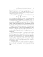
Adhesives and epoxies are comprised of a bonding material filled with metal
flakes as shown in Figure 12.2. Typically, silver flakes are used as the metal filler
since it has good electrical conductivity and has been shown not to migrate through
the die-attach material.
3,4
These die-attach materials have the advantage of lower
process temperatures. Generally between 100 and 2008C are required to cure the
material. They also have a lower built-in stress from the assembly process as
compared to solder attachment. Furthermore, since the die attach does not create
a rigid assembly, shear stresses caused by thermal cycling and mechanical forces
are relieved to some extent.
5,6
One particular disadvantage of the soft die-attach
materials is that they have a significantly higher electrical resistivity which is 10 to
50 times greater than solder and a thermal resistivity which is 5 to 10 times greater
than solder. Lastly, humidity has been shown to increase the aging process of the
die-attach material.
4
12.4 THERMAL MANAGEMENT CONSIDERATIONS
For small signal circuits, the temperature of the device junction does not increase
substantially during operation, and thermal dissipation from the MEMS is not a
problem.
However, with the push to increase the integration of MEMS with power from
other circuits such as amplifiers perhaps even within a single package, the tem-
perature rise in the device junctions can be substantial and cause the circuits to
operate in an unsafe region. Therefore, thermal dissipation requirements for power
MEMS device
Package base
Die-attach
material
Ag flakes
FIGURE 12.2 Schematic representation of silver filled epoxy resin.
Osiander / MEMS and microstructures in Aerospace applications DK3181_c012 Final Proof page 276 1.9.2005 9:13pm
276 MEMS and Microstructures in Aerospace Applications
© 2006 by Taylor & Francis Group, LLC
amplifiers, other large signal circuits, and highly integrated packages can place
severe design constraints on the package design. The junction temperature (T
j
)ofan
isolated device can be determined by
T
j
¼ QR þ T
case
(12:2)
where
Q (W) is the heat dissipated by the junction and is dependent on the output power
of the device and its efficiency,
R (8C/W) is the thermal resistance between the junction and the case, and
T
case
(8C) is the temperature of the case.
Normally, the package designer has no control over Q and the case temperature,
and therefore, it is the thermal resistance of the package that must be minimized.
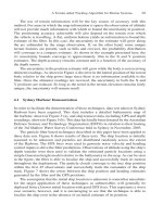
Figure 12.3 is a schematic representation of the thermal circuit for a typical
package, where it is assumed that the package base is in contact with a heat sink
or case.
It is seen that there are three thermal resistances that must be minimized: the
resistance through the package substrate, the resistance through the die-attach
material, and the resistance through the carrier or package base. Furthermore, the
thermal resistance of each is dependent on the thermal conductance and the
thickness of the material. A package base made of metal or metal composites has
very low thermal resistance and therefore does not add substantially to the total
resistance. When electrically insulating materials are used for bases, metal-filled via
holes are routinely used, under the MEMS, to provide a thermal path to the heat
sink. Although thermal resistance is a consideration in the choice of the die-attach
material, adhesion and bond strength are even more important. To minimize the
thermal resistance through the die-attach material, the material must be thin, there
can be no voids, and the two surfaces to be bonded should be smooth.
Q
R-
MMIC
R-die attach
R-package
Package base
MMIC
Heat sink or case
FIGURE 12.3 Cross section of MMIC attached to a package and its equivalent thermal
circuit.
Osiander / MEMS and microstructures in Aerospace applications DK3181_c012 Final Proof page 277 1.9.2005 9:13pm
MEMS Packaging for Space Applications 277
© 2006 by Taylor & Francis Group, LLC
12.5 MULTICHIP PACKAGING
12.5.1 MCM/HDI
Multichip packaging of MEMS can be a viable means of integrating MEMS with
other microelectronic technologies such as complementary metal oxide semicon-
ductor (CMOS). One of the primary advantages of using multichip packaging, as a
vehicle for MEMS and microelectronics, is the ability to efficiently host die from
different or incompatible fabrication processes into a common substrate. High-
performance multichip module (MCM) technology has progressed rapidly in the
past decade, which makes it attractive for use with MEMS.
The chip-on-flex (COF) process has been adapted for the packaging of MEMS.
7
One of the primary areas of the work was reducing the potential for heat damage to
the MEMS devices during laser ablation. Additional processing has also been added
to minimize the impact of incidental residue on the die.
8
12.5.1.1 COF/HDI Technology
COF is an extension of the high density interconnect (HDI) technology developed
in the late 1980s. The standard HDI ‘‘chips first’’ process consists of embedding
bare die in cavities milled into a ceramic substrate and then fabricating a layered
thin-film interconnect structure on top of the components. Each layer in the HDI
interconnect overlay is constructed by bonding a dielectric film on the substrate and
forming via holes through laser ablation. The metallization is created through
sputtering and photolithography.
9
COF processing retains the interconnect overlay used in HDI, but molded
plastic is used in place of the ceramic substrate. Figure 12.4 shows the COF process
flow. Unlike HDI, the interconnect overlay is prefabricated before chip attachment.
After the chip(s) have been bonded to the overlay, a substrate is formed around the
components using a plastic mold forming process such as transfer, compression, or
injection molding. Vias are then laser drilled to the component bond pads and the
metallization is sputtered and patterned to form the low impedance interconnects.
10
For MEMS packaging, the COF process is augmented by adding a processing
step for laser ablating large windows in the interconnect overlay to allow physical
access to the MEMS devices. Figure 12.5 depicts the additional laser ablation step
for MEMS packaging. Additional plasma etching is also included after the via-
drilling and large area laser ablations to minimize adhesive and polyimide residue
that accumulates in the exposed windows.
12.5.2 FLIP-CHIP
Controlled collapse chip connection (C4) is an interconnect technology developed
by IBM during the 1960s as an alternative to manual wire bonding. Often called
‘‘flip-chip,’’ C4 attaches a chip top-face-down on a package substrate as shown in
Figure 12.6. Electrical and mechanical interconnects are made by means of plated
solder bumps between bond pads and metal pads on the package substrate.
Osiander / MEMS and microstructures in Aerospace applications DK3181_c012 Final Proof page 278 1.9.2005 9:13pm
278 MEMS and Microstructures in Aerospace Applications
© 2006 by Taylor & Francis Group, LLC
individual functions are processed on a single piece of silicon. These processes,
generally CMOS technology, are compatible with the MEMS processing technol-
ogy. Most SOAC chips are designed with a microprocessor of some type, some
memory, some signal processing and others. It is very conceivable that a MEMS
device could one day be incorporated on a SOAC.
12.6 EXAMPLE APPLICATIONS OF MEMS FOR SPACE
Many types of MEMS devices have been proposed for application to space
systems, all of which serve to reduce size, weight, cost, and power consumption.
Examples of common sensors and actuators that are considered for space appli-
cations include inertial sensors such as accelerometers, gyroscopes, and magnet-
ometers; remote sensors such as spectrometers, shutters or filters, bolometers,
and optical elements; and subsystems such as propulsion and active mechanical
and thermal control systems. This section will focus on MEMS packaging
technologies incorporated in applications of space-science instruments and sub-
systems.
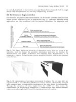
12.6.1 VARIABLE EMITTANCE COATING INSTRUMENT FOR
SPACE TECHNOLOGY 5
Novel packaging techniques that are needed to place MEMS-based thermal control
devices on the skin of a satellite are addressed in the Variable Emittance Coating
Instrument developed by the Johns Hopkins University Applied Physics Laboratory
(JHU/APL). The instrument consists of two components: the MEMS shutter array
(MSA) radiator and the electronic control unit (ECU). The MSA radiator is located
on the bottom deck of the spin-stabilized Space Technology 5 (ST5) spacecraft,
whereas the ECU is located within the spacecraft.
The instrument consists of an array of 36 dies, each 12.65 Â 13.03 mm, which
consists of arrays of 150-mm long and 6-mm wide shutters driven by electrostatic
comb drives, mounted on a radiator. The gold-coated shutters open and close over
the substrate and change the apparent emittance of the radiator. The device had to
be on the exposed side of the radiator, and any cover had to be infrared transparent
well into the far infrared. An additional requirement was that the substrate be
thermally and electrically coupled to the radiator to allow heat transfer and preven-
tion of electric charging effects.
In order to manage the thermal expansion mismatch between Al and Si for the
survival temperature range, À45 to 658 C, an intermediate carrier made from
aluminum nitrate was used. Sets of six dies, with wirebonds connecting all the
common inputs, are attached to the aluminum nitride substrate, shown in Figure
12.7, with conductive epoxy, which themselves are attached to the aluminum
radiator with epoxy. The radiator package contains heaters and is pigtailed to the
connectors for the electronic control unit inside the spacecraft.
A photograph of the entire package is shown in Figure 12.8. In order to
eliminate the concern associated with potential particulates from integration and
Osiander / MEMS and microstructures in Aerospace applications DK3181_c012 Final Proof page 281 1.9.2005 9:13pm
MEMS Packaging for Space Applications 281
© 2006 by Taylor & Francis Group, LLC
beryllium copper. This total of five layers of materials aligned and stacked in an
alternating fashion provided some unique assembly and packaging challenges. Each
silicon layer has five dies (one per pixel) with an array of aperture slits on each die.
The CuBe plates were precision machined to achieve the array of channels, each
with a fixed field-of-view, with placement accuracy between arrays sufficient to
allow for the integration of an array of five silicon die. The wafers were diced such
that each of the five dies could be individually aligned and bonded to the CuBe
plates using a flip-chip die-attach bonding technique. Low stress conductive and
nonconductive epoxies were selected for bonding the five layers to each other
because of high mismatches in coefficients of thermal expansion between the
silicon and CuBe. The bonded components of the sensor head were packaged within
the iridite-plated aluminum supporting structure via mounting brackets and alumi-
num rods used for maintaining a 1-mm offset to the MCP. The lower flange of
the MCP was adhesively attached to the insulating mounting plate, which is
attached to the housing with screws around the perimeter. The remaining
items were assembled and packaged into the spacecraft mechanical interface
housing using 2–56 and 4–40 screws. Spot welding a high voltage lead to
the upper and lower plates of the MCP provided electrical connection from
the HV power supply. A AuNi plated Kovar lead was welded to the CuBe electro-
static analyzer in order to provide an accessible site for soldering a scan
voltage supply and ground wire from the PCB. An Sn63Pb37 solder was used to
connect the power supply to the PCB, and from each preamplifier discriminator
circuit on the PCB to the plated through vias on each anode. In addition, ensuring a
conductive bleed path from every conductive surface to spacecraft ground mitigated
potential charging effects. The packaging scheme of the FlaPS instrument is
illustrated in Figure 12.9.
12.6.3 MICROMIRROR ARRAYS FOR THE JAMES WEBB SPACE TELESCOPE
In support of the James Webb Space Telescope (JWST), equipped with the multi-
object-spectrometer, individually addressable MEMS mirror arrays serving as a slit
mask for the spectrometer, will selectively direct light rays from different regions of
space into the spectrometer. An integrated micromirror array or CMOS driver chip
was designed at NASA GSFC. System requirements posed several challenges to
the packaging of the integrated MEMS chips. However, flip-chip technology
to bump-bond the large chips (9 Â 9 cm) onto a silicon substrate in a 2 Â 2 mosaic
pattern was used to eliminate the concern for global thermomechanical stresses
due to mismatched coefficients of thermal expansion between the chip and sub-
strate. Alignment of the chips forming the mosaic pattern was also a critical
system specification. The relative tilt angle between the chips was held within
0.058 by making use of the restoring force of the solder bumps to self-align the
chips during flip-chip solder reflow. The attached MMA or CMOS assembly was
placed inside a package and fixed via peripheral pressure contacts. And, finally,
input or output leads were made via tape-automated bonding from the package to
the chips.
14
Osiander / MEMS and microstructures in Aerospace applications DK3181_c012 Final Proof page 284 1.9.2005 9:13pm
284 MEMS and Microstructures in Aerospace Applications
© 2006 by Taylor & Francis Group, LLC
approaches for MEMS in space applications. As shown, most designs and materials
are still based on the experience with the semiconductor devices. In order to
accelerate the introduction of MEMS into spacecraft, more flight opportunities
are neseccary to allow a selection of packaging approaches, and a strong exchange
of knowledge is required between the engineers and space institutions to omit error
repetition. This chapter should help to get this exchange started.
REFERENCES
1. Muller, L., M.H. Hecht, et al., Packaging and qualification of MEMS-based space
systems, Proceedings of the 1995 9th Annual International Workshop on Micro Electro
Mechanical Systems, February 11–15 1996, San Diego, CA, USA, IEEE, Piscataway, NJ,
USA, 1996.
2. Moor, A., et al., The case for plastic encapsulated microcircuits in space flight applica-
tions, The Johns Hopkins University Applied Physics Lab Technical Digest, Vol. 20,
No. 1, 1999.
3. Hvims, H.L., Conductive adhesives for SMT and potential applications, IEEE Transac-
tions on Components, Packaging, and Manufacturing Technology — Part-B, Vol. 18,
No. 2, pp. 284–291, May 1995.
4. Rusanen, O. and J. Lenkkeri, Reliability issues of replacing solder with conductive
adhesives in power modules, IEEE Transactions on Components, Packaging, and Manu-
facturing Technology — Part-B, Vol. 18, No. 2, pp. 320–325, May 1995.
5. Tuhus, T. and A. Bjomeklett, Thermal cycling reliability of die bonding adhesives, 1993
IEEE Annual International Reliability Physics Symposium Digest, 208 pp, March 23–25,
1993.
6. Yalamanchili, P. and A. Christou, Finite element analysis of millimeter wave MMIC
packages subjected to temperature cycling and constant acceleration, 1993 GaAs REL
Workshop Programs and Abstracts, October 10, 1993.
7. Butler, J., V. Bright, and J. Comtois, Advanced multichip module packaging of micro-
electromechanical systems, Tech Digest of the 9th International Conference on Solid-
State Sensors and Actuators (Transducers ’97), Vol. 1, pp. 261–264, June 1997.
8. Butler, J., V. Bright, R. Saia, and J. Comtois, Extension of high density interconnect
multichip module technology for MEMS packaging, SPIE, Vol. 3224, pp. 169–177, 1997.
9. Daum, W., W. Burdick Jr., and R. Fillion, Overlay high-density interconnect: a chips-
first multichip module technology, IEEE Computer, Vol. 26, No. 4, pp. 23–29, April
1993.
10. Filtion, R., R. Wojnarowski, R. Saia, and D. Kuk, Demonstration of a chip scale chip-on-
flex technology, Proceedings of the 1996 International Conference on Multichip Mod-
ules, SPIE, Vol. 2794, pp. 351–356, April 1996.
11. Maluf, N., An Introduction to Microelectromechanical Systems Engineering, Artech
House, Inc, Boston, 2000.
12. Darrin, M.A., R. Osiander, J. Lehlonen, D. Farrar, D. Douglas, and T. Swanson, Novel
micro electro mechanical systems (MEMS) packaging for the skin of the satellite,
Proceedings of 2004 IEEE Aerospace Conference 4, pp. 2486–2494, 2004.
13. Wesolek, D.M., A. Darrin, R. Osiander, J.S. Lehtonen, R.L. Edwards, and F.A. Hererro,
Micro processing a path to aggressive instrument miniaturization for micro and picosats,
2005 IEEE Aerospace Conference, March 2005, Big Sky, Montana.
Osiander / MEMS and microstructures in Aerospace applications DK3181_c012 Final Proof page 286 1.9.2005 9:13pm
286 MEMS and Microstructures in Aerospace Applications
© 2006 by Taylor & Francis Group, LLC
14. Lu, G Q., J. Calata, et al., Packaging of large-area, individually addressable, micro-
mirror arrays for the next generation space telescope. Design, Test, Integration, and
Packaging of MEMS/MOEMS 2002, May 6–8 2002, Cannes, France, 2002.
Osiander / MEMS and microstructures in Aerospace applications DK3181_c012 Final Proof page 287 1.9.2005 9:13pm
MEMS Packaging for Space Applications 287
© 2006 by Taylor & Francis Group, LLC
13
Handling and
Contamination Control
Considerations for Critical
Space Applications
Philip T. Chen and R. David Gerke
CONTENTS
13.1 Introduction 289
13.2 Wafer Handling 290
13.3 Handling during Die Singulation, Release, and Packaging 291
13.3.1 Die Singulation 291
13.3.2 Handling during Release 291
13.3.3 Packaging 292
13.4 In-Process Handling and Storage Requirements 293
13.5 Electrostatic Discharge Control 294
13.6 Contamination Control 295
13.6.1 Contamination Control Program 295
13.6.2 MEMS Contamination Control 296
13.6.3 Contamination Controls during Fabrication 298
13.6.4 MEMS Package Contamination Control 298
13.6.5 MEMS Postpackage Contamination Control 301
13.6.6 Contamination Control on Space Technology 5 303
13.7 Conclusion 306
References 306
13.1 INTRODUCTION
No characteristic of microelectromechanical systems (MEMS) devices sets them
apart from integrated circuits (ICs) more clearly than their sensitivity to surface
contamination. An IC wafer leaves the foundry passivated for normal environmen-
tal exposure; a MEMS wafer does not. As a result, standard back-end processing
steps (dicing, pick and place, die attach, wire bonding or bumping, and packaging)
commonly used for ICs cannot be used for MEMS.
Osiander / MEMS and microstructures in Aerospace applications DK3181_c013 Final Proof page 289 1.9.2005 12:45pm
289
© 2006 by Taylor & Francis Group, LLC
(quantity and location), manufacturing processes, integration and test, packing and
packaging, transportation, launch, on-orbit operations, and return to Earth, if ap-
plicable. In addition, the assessment should identify the types of substances that
may contaminate and cause unacceptable degradation. The assessment results serve
as a general guideline to how extensive a CCP should be instituted.
Actual contamination control implementation of MEMS devices can be divided
into three major levels: design, packaging, and postpackaging. In the design level,
contamination control is focused in MEMS device configuration, operation condi-
tions, and material selection with an aim to minimize the contamination generation
potential. At the MEMS packaging level, adequate fabrication, assembly environ-
ments and processes are key to prevent contaminants from reaching MEMS devices.
The postpackaging level includes the integration and test of MEMS devices with
spacecraft and transport until their final operations on-orbit. At this final stage,
contamination control is essential in reducing accumulation of contaminants and
mitigating contamination impact on MEMS devices.
TABLE 13.2
Mission Specific Environments and Contamination Sources
Mission Phase Molecular Particulate
Design Configuration, operation conditions,
material selection
Configuration, operation conditions,
material selection
Fabrication Materials outgassing, machining oils,
fingerprints, air fallout
Shedding, flaking metal chips, filings,
particle fallout, personnel
Assembly AMC, outgassing, personnel,
cleaning, solvents, soldering,
lubricants, bagging material
Particle fallout, personnel, soldering,
drilling, bagging material, shedding,
flaking
Integration and test AMC, outgassing, personnel, test
facilities, purges
Particle fallout, personnel, test facilities,
purges, shedding, flaking,
redistribution
Storage Bagging material, outgassing,
purges, containers
Bagging material, purges, containers,
shedding, flaking
Transport Bagging material, outgassing,
purges, containers
Bagging material, purges, containers,
vibration, shedding, flaking
Launch Site Site bagging material, AMC,
outgassing, personnel, purges
bagging material, air fallout
Bagging material, particle fallout,
personnel, shedding, flaking,
checkout activities, other payload
activities
Launch Ascent outgassing, venting, engines,
companion payloads separation
maneuvers
Vibration and redistribution, venting,
shedding, flaking
On-orbit Outgassing, UV interactions, atomic
oxygen, propulsion systems
Micrometeoroid and debris
impingement, material erosion,
redistribution, shedding, flaking,
operational events
Osiander / MEMS and microstructures in Aerospace applications DK3181_c013 Final Proof page 297 1.9.2005 12:45pm
Handling and Contamination Control for Critical Space Applications 297
© 2006 by Taylor & Francis Group, LLC