MEMS and Microstructures in Aerospace Applications - Robert Osiander et al (Eds) Part 13 pot
Bạn đang xem bản rút gọn của tài liệu. Xem và tải ngay bản đầy đủ của tài liệu tại đây (570.43 KB, 11 trang )
The goal of contamination control at the design level is to minimize contamin-
ation sources and to remove contaminants from MEMS devices whenever it is
feasible on-ground or on-orbit. By eliminating contaminants before they ever have
chance to generate, this design level contamination control is not only effective but
also very cost-saving. Unfortunately this critical stage of contamination control is
often neglected due to the lack of the involvement from a contamination engineer.
Material selections for MEMS devices are critical for effective contamination
control. Single-crystal Si, polysilicon, Si
3
N
4
, and SiO
2
, and other materials are
well recognized for constructing MEMS devices. In addition SiC, shape memory
alloy (SMA) metals, permalloy, and high-temperature superconductive materials
are potential candidates. Although these materials have certain unique properties
which are attractive for certain MEMS applications, contamination issues may
result from the usage of these materials. For example, silica material used in fiber
optics is brittle and is prone to fracture including delayed fracture.
13.6.3 CONTAMINATION CONTROLS DURING FABRICATION
Contamination concerns start at the beginning of the MEMS fabrication life.
Problem areas in the foundry can be with both inferior materials and chemicals or
due to inadequate or not followed processing steps. Entire lots due to the homoge-
neous nature of fabrication runs may need to be destroyed due to contamination
related yield losses such as streamers, corrosion, and other results from impurities
or improper processing. The greater concern at the foundry level is allowing
contamination to reside with a lot only to appear at a later date found through
failure of the component. At the foundry level the most common source of con-
tamination is organics that have not been adequately removed. Most foundries ship
product with the photoresists still present, which protect the MEMS from damage,
but are absolutely necessary to be removed prior to release. Other sources of
contamination include those from humans such as finger oils, makeup, human
spittle, and processing materials. Often, dicing films are special adhesives that
must be properly removed. Bubbles forming during the release step can ‘‘protect’’
the material in the sacrificial area yielding a nonfunctioning or only partially
functioning device.
The recommended solvent should be used to assure the complete removal of
organics. Oxygen plasma and piranha etch are often used. Oxygen plasma is just
gaseous oxygen electrically charged into plasma. Organics placed in oxygen plasma
will etch quite thoroughly. Piranha etch is an etching compound formed of 70%
sulfuric acid and 30% hydrogen peroxide that will consume almost all organics, but
leave behind nonorganics. Piranha etch can remove some metal so it is necessary to
test pieces before committing a lot to any particular solution.
13.6.4 MEMS PACKAGE CONTAMINATION CONTROL
The discussion of package level contamination control for MEMS devices for space
flight use must be devoted to controlling contaminants from damaging the devices.
Risk of contamination is present at the bare die level, packaged, and through
Osiander / MEMS and microstructures in Aerospace applications DK3181_c013 Final Proof page 298 1.9.2005 12:45pm
298 MEMS and Microstructures in Aerospace Applications
© 2006 by Taylor & Francis Group, LLC
on-orbit. MEMS package contamination control requires comprehensive contamin-
ation control protocols for fabrication and assembly. The contamination effort deals
with both molecular and particulate contaminants resulted from facility environ-
ments and packaging procedures. It is important not to jump to the conclusion that
contamination is the culprit. The types of failures associated with stiction and
particulates could also be caused by design or manufacturing discrepancies such
as over or under etching.
10–12
The bulk of today’s MEMS devices are manufactured in the traditional semi-
conductor clean room facilities with air cleanliness ranges from Class 100 to Class
10,000 per FED-STD-209. Examples of damage caused by unwanted molecular and
particulate contamination suggest the deficiency of conventional facility, equip-
ment, and process at the MEMS package level. One hard-to-detect failure in MEMS
devices is particulate contamination that occurs during fabrication. The effect
produced by dust adhering to the wafer in the water process differs according to
the process. Particles also affect thermal management in photonic packages.
A typical edge-emitting communications laser diode will have an energy flux
through the facet of up to 2 million watts per square centimeter. The influence of
even slight levels of impurities or contaminating particles is disastrous for thermal
control. Therefore, the best contamination control approach is to not allow contam-
inants to generate, stay around, and finally adhere to surfaces.
Contamination-induced effects can be reduced by fabricating MEMS devices in
a better clean room facility with more stringent clean room protocols. Class 100
clean room environments with localized Class 10 work areas are optimal for post-
singulation processing. As a minimum, the device should be in a Class 100 clean
room environment from its release point until it is safely sealed in a clean, hermetic
package. Dust generated by equipment adheres directly to wafers, and thus has a
large effect. Sufficient consideration should be given to dust when selecting equip-
ment models; it is also important for device manufacturers to take steps to reduce
dust generation when setting process conditions or performing maintenance during
production. It is important to package MEMS devices in a controlled, hermetic,
particle-free environment. Every step, from die preparation to package seal, must be
performed in a Class 100 clean room environment until the device is safely sealed in
a clean hermetic package. Clean room techniques normally reserved only for wafer
fabrication must be extended to the probe, die-prep, and assembly areas.
Further contamination control improvement can be achieved by implementing
better assembly processes for MEMS devices. Certain unwanted organic compound
residues in the adhesives can lead to catastrophic optical damage (COD) of the laser
die. Outgassing occurs when materials used for die attach, bump preparation, or
packaging are included in the hermetic cavity. Improved processes keep these
materials from being included in the package, thus eliminating potential contamin-
ation sources. Because the process takes place at wafer scale, the cavity formed can
be arranged to include only the active MEMS device. With this approach, materials
known to create outgassing effects are simply excluded from the hermetic cavity.
For particulate contamination, Blanton and others at CMU have developed a
tool called contamination and reliability analysis of microelectromechanical layout
Osiander / MEMS and microstructures in Aerospace applications DK3181_c013 Final Proof page 299 1.9.2005 12:45pm
Handling and Contamination Control for Critical Space Applications 299
© 2006 by Taylor & Francis Group, LLC
(CARAMEL) for analyzing the impact of particles on the structural and material
properties of surface-micromachined MEMS. CARAMEL accepts as input a micro-
electromechanical design represented as a layout in Caltech Interchange Format
(CIF), a particulate description, and a process (fabrication) recipe. It performs
process simulation that includes the foreign particle and creates a three-dimensional
representation of the resulting defective microelectromechanical structure. CARA-
MEL then extracts a mesh netlist representation of the defective structure whose
form is compatible with finite-element analysis (FEA) tools. Performing FEA of the
CARAMEL mesh output correlates the contamination of concern to a defective
structure and a faulty behavior. CARAMEL has been used to investigate the impact
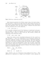
of particles on electrostatic comb-drive actuated microresonator.
13
This technique is
demonstrated on a resonator as shown in Figure 13.1. Interestingly enough, experi-
ments through CARAMEL reveal that the resonator is susceptible to a variety of
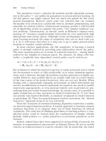
misbehaviors as a result of a single particle contamination. Figure 13.2 shows two
representative defects caused by particles.
Protection of MEMS devices from the environment is an important concern as a
hermetic package significantly increases the long-term reliability of the devices.
Traditional hermetic IC packaging techniques, when applicable, offer protection
from contamination; however, only a subset of devices can be packaged in this
manner. This subset includes accelerometers, which may be packaged with the
hermetic schemes used for ICs. Numerous devices however require interaction with
the environment such as gas detectors, optical switches (requiring optical windows)
and lab-on-chip systems. In this case, while functionality must be maintained,
vulnerabilities must be reduced. MEMS devices, which require free space to
function, may be at particular risk. There are few standardized solutions to this
problem and for the low quantities required by the space industry most solutions
will be customized.
fixed
finger
shuttle mass
movable
finger
fin
g
er
g
ap
anchors
inner
beam
outer
beam
spring
beam
FIGURE 13.1 Top view of a surface-micromachined, electrostatic comb-drive actuated
structure that is suspended over the die substrate and is anchored only at the shuttle
movement to a capacitance change between the moveable and fixed potential difference
between the shuttle and fixed fingers, or from an inertial force caused by external acceler-
ation. (Courtesy: CMU S. Blanton.)
Osiander / MEMS and microstructures in Aerospace applications DK3181_c013 Final Proof page 300 1.9.2005 12:45pm
300 MEMS and Microstructures in Aerospace Applications
© 2006 by Taylor & Francis Group, LLC
are needed for nonhermetically packaged MEMS devices that are more susceptible
to contaminants. Measures to protect nonhermetically packaged MEMS devices,
may include temperature control, humidity control, gas purging, and protective
enclosures. In addition, for nonhermetically sealed MEMS devices, especially if
mounted on the skin of the spacecraft, the need to identify the component and ‘‘red
tag’’ the item for special handling is essential.
MEMS postpackage level contamination control is concentrated on maintaining
proper surface cleanliness levels, that is, molecular and particulate contamination
budget. Therefore, the amount of performance degradation that is allowed for
MEMS contamination-sensitive surfaces needs to be established. From this degrad-
ation limit, the amount of contamination that can be tolerated, that is, the contam-
ination allowance, can be established. This allowable degradation should also be
included as a contamination budget stated in CCP.
The contamination budget describes the quantity of contaminant and the deg-
radation that may be expected during various phases in the lifetime of a MEMS
device. The established contamination budget for MEMS devices is monitored as
the program progresses. When the contamination budget exceeded requirements,
MEMS surfaces may be cleaned periodically to reestablish a budget baseline. In
addition, contamination-preventive methods, such as clean rooms and MEMS
device covers, should be included.
The integration and test (I&T) of conventional spacecraft is generally per-
formed in clean rooms with air cleanliness classes ranges from Class 1000 to as
high as Class 100,000. Integration through launch conditions may provide numer-
ous opportunities for gaseous and particulate contaminants to be deposited on
MEMS surfaces. For optical MEMS (MOEMS) gaseous contaminants can degrade
performance by condensing on critical windows or alternatively by absorbing light
along the line-of-sight.
There is a concern for MEMS devices when they are exposed to uncontrolled
ambient humidity. During I&T, MEMS devices with sliding and rotational motion
may experience wear since speeds can approach 1 million rpm in the devices.
According to study results from Sandia National Laboratory, the RH is critical for
proper operations of MEMS devices. Low humidity may increase resistance and
wear of MEMS devices, while high humidity may cause corrosion, wear, and
stiction. The ideal range appears to be somewhere between 20 and 60% for the
I&T of MEMS devices. However, specific RH requirements may depend on distinct
MEMS hardware design and applications.
As stated in Table 13.2, considerable amounts of contaminants may be
generated during launch and on-orbit operations. Microscopic particles can dislodge
or even form during these operations. To prevent contaminants, materials with
a less potential of generating particles should be chosen for fabricating MEMS
devices. Besides particles, material outgassing as a major contamination source is
also a well-recognized fact. Outgassed contaminants are greatly promoted by the
space environments of high vacuum and elevated temperatures. On-orbit degrad-
ation due to contamination can truncate the mission lifetime and degrade data
quality. These degradations may include long-term changes in the optical surfaces
Osiander / MEMS and microstructures in Aerospace applications DK3181_c013 Final Proof page 302 1.9.2005 12:45pm
302 MEMS and Microstructures in Aerospace Applications
© 2006 by Taylor & Francis Group, LLC
or changes in absorptivity of a thermal control surface, which will eventually reduce
its effectiveness and cause loss of performance. It is necessary to minimize contri-
bution to spacecraft contamination through outgassing product in modern MEMS
packaging materials. All nonmetallic materials should be selected for low
outgassing characteristics and baked out in meeting their outgassing requirements.
The thermal vacuum bake is an effective method to assure that outgassed
materials have been removed. Generally, the hotter and longer the item can be
baked, the better the chance that the item will not contaminate the chamber or test
article. Space flight hardware are typically baked at 508C or higher, under 5 Â 10
À6
torr vacuum environment for at least 48 h unless otherwise noted. Visible degradation
of the material during bakeout will obviously result in the rejection of the material.
Some materials must be qualified for use by monitoring the outgassing levels during
the bakeout. The use of MSFC-SPEC-1238
14
is recommended for critical optical
applications. Bakeouts of MEMS devices are required unless it can be satisfactorily
demonstrated that the contamination allowance can be met without bakeouts.
MEMS devices operated on-orbit require proper protection from various
contamination sources. Plume impingement poses a great threat to MEMS devices
with both thermal heating and contamination degradation effects. Propulsion sys-
tems and attitude control systems are major contributors to plume contamination.
Plumes contain particulates that may be impinged on the exposed surfaces. For
example, solid rocket motors emit Al
2
O
3
and gaseous HCl, H
2
O, CO, CO
2
,N
2
, and
H
2
. The shuttle Orbiter and International Space Station may also release water
vapor and ice particles along with gases leaking from the pressurized cabins.
15
To
warrant proper on-orbit operations, it is necessary to protect MEMS devices from
plume impingement. The protection is attained by a combination of mitigation
methods including placing plume shields, optimizing thruster operations, or install-
ing active decontamination devices.
13.6.6 CONTAMINATION CONTROL ON SPACE TECHNOLOGY 5
The Space Technology 5 (ST5) mission, as part of NASA’s New Millennium
Program (NMP), is a technology demonstration mission designed and managed
by NASA Goddard Space Flight Center (GSFC) that consists of three nanosatellites
flying in Earth’s magnetosphere. A thermal management method developed by
NASA and JHU/APL as one of the demonstration techniques of variable emittance
surfaces is a MEMS-based device that regulates the heat rejection of the small
satellite.
16
This system consists of MEMS arrays of gold-coated sliding shutters,
fabricated with the Sandia ultraplanar, multilevel MEMS technology fabrication
process, which utilizes multilayer polycrystalline silicon surface micromachining.
The shutters can be operated independently to allow digital control of the effective
emissivity.
For variable emissivity radiators the concerns of contamination and
handling drove the packaging design. The shutters open only 6 mm by 105 mm
with a concern that a small particle can lodge in the devices within the hinges of
the MEMS shutters and prohibit movement. Placing a protective window over the
Osiander / MEMS and microstructures in Aerospace applications DK3181_c013 Final Proof page 303 1.9.2005 12:45pm
Handling and Contamination Control for Critical Space Applications 303
© 2006 by Taylor & Francis Group, LLC
MEMS shutter array (MSA) was the obvious solution, but even the protective
window must meet the NASA GSFC material requirements. In this application
the external surface of the window must be electrically conductive, and if made of
an organic material, must be resistant to the attack by atomic oxygen in space. In
addition, for the shutter application, high infrared transparency was required.
The protective windows used are a fluorinated polyimide material developed by
NASA Langley Research Center (LaRC) located in Newport News, Virginia.
LaRC-CP1
1
polyimide is a high-performance material with a wide variety of
uses in space structures, thermal insulation, electrical insulators, industrial tapes,
and advanced composites. This polyimide material may be dissolved readily in a
number of solvents for use in various applications such as castings and coatings.
CP1 was selected for the ST5 application for its infrared transparency and space
environment survivability for a 10-year life in geosynchronous earth orbit (GEO).
CP1 is colorless and offers better space UV-radiation resistance than most known
polymer materials (including other polyimides, polyesters, Teflon, Teflon-based
materials, and others). The MEMS dies are fabricated in wafer format using
Sandia’s processing as described in Chapter 3. The wafers go through a standard
backside grind process and then are released, diced, tested, gold coated, and
functionally tested again, in preparation for final attach. The individual dies are
bonded to aluminum nitride (AlN) carriers that are subsequently bonded to the
MSA chassis. This design allows for optimum rework or replacement of each
MEMS shutter die (MSD) as necessary.
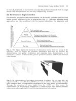
Of most significance is the window assembly. As stated previously, the micro-
machined comb drives are sensitive to the abundant contamination in space. The
CP1 fluorinated polyimide material was selected for the fabrication of MEMS
device. A CP1 film, less than 4 mils thick, is sandwiched in tension between two
window frames and bonded in place, as shown in Figure 13.3. CP1 in its relaxed
FIGURE 13.3 MSA radiator assembly. (Source: JHU/APL.)
Osiander / MEMS and microstructures in Aerospace applications DK3181_c013 Final Proof page 304 1.9.2005 12:45pm
304 MEMS and Microstructures in Aerospace Applications
© 2006 by Taylor & Francis Group, LLC
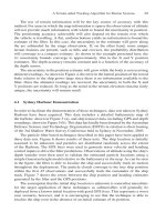
FIGURE 13.4 Exploded view of the MSA radiator assembly. (Source: JHU/APL.)
Osiander / MEMS and microstructures in Aerospace applications DK3181_c013 Final Proof page 305 1.9.2005 12:45pm
Handling and Contamination Control for Critical Space Applications 305
© 2006 by Taylor & Francis Group, LLC
state is flaccid and must be stretched to provide the mechanical protection
from debris impact. To ensure a taut connection, the CP1 is procured in a taut
configuration, and then epoxied to one side of the window and then cured. Sand-
wiching the CP1 attach between the two windows, reinforces the connection.
With the window assembly in place, the CP1 film is suspended several millimeters
above the shutters, thus providing a barrier layer between the actual die and the
environment.
Electrical conductivity of the film is achieved through application of a thin coating
of indium tin oxide (ITO), a transparent electrical conductor. In sufficiently thin
coatings ITO does not change the IR performance of the window. ITO coating serves
to protecttheCP1fromdegradation in thepresenceof atomic oxygen. All thestructural
members of the MEMS shutter array radiator assembly were made of aluminum 6061
and finished with a clear anodize treatment, followed by a yellow irridite.
An exploded view of the MSA radiator assembly is shown in Figure 13.4.
Additional information on the packaging of MEMS devices is found in Chapter 12
but clearly contamination, handling concerns, and functionality are the key ingre-
dients to successful packaging scheme.
13.7 CONCLUSION
For space applications, MEMS devices are susceptible to environment-induced
damage both on-ground and on-orbit. The potential damage may occur at any
stage of the mission but they are especially prone to surface contamination prior
to the prepackage phase.
The damage impact is alleviated by implementing prudent handling and con-
tamination control practices. Facility for manufacturing and assembly must be
maintained at adequate cleanliness conditions with proper procedures established.
Personnel handling MEMS devices must be properly trained with special attention
to preclude ESD damage to the devices. To achieve the best protection, MEMS
devices must be isolated in a hermetic package or protected with covers whenever
possible.
CCP delineates a comprehensive contamination control program for a mission.
MEMS devices as an integral part of the mission must follow handling and
contamination guidelines established in the CCP in order to meet mission require-
ments.
REFERENCES
1. C.H. Mastrangelo and G.S. Saloka, Dry-release method based on polymer columns for
microstructure fabrication, Proceedings of the 1993 IEEE Micro Electro Mechanical
Systems — MEMS, February 7–10 1993, Fort Lauderdale, FL, USA, IEEE, Piscataway,
New Jersey, pp. 77–81 (1993).
2. G.T. Mulhern, D.S. Soane, and R.G. Howe, Supercritical carbon dioxide drying for
microstructures, Proceedings of the 7th International Conference on Solid-State Sensors
and Actuators, Transducers ’93, Yokohama, Japan, pp. 296–299 (1993).
Osiander / MEMS and microstructures in Aerospace applications DK3181_c013 Final Proof page 306 1.9.2005 12:45pm
306 MEMS and Microstructures in Aerospace Applications
© 2006 by Taylor & Francis Group, LLC
3. H. Watanabe, S. Ohnishi, I. Honma, H. Kitajima, H. Ono, R.J. Wilhelm, and A.J.L.
Sophie, Journal of the Electrochemical Society, 142, 237–243 (1995).
4. S. Brown, C. Muhlstein, C. Abnet, and C. Chui, MEMS testing techniques for long-term
stability, Proceedings of the 1998 ASME International Mechanical Engineering Con-
gress and Exposition, November 15–20 1998, Anaheim, CA, USA, ASME, Fairfield, NJ,
USA, p. 145 (1998).
5. R. Ramesham, R. Ghaffarian, and N.P. Kim, Proceedings of SPIE — Reliability Issues of
COTS MEMS for Aerospace Applications, 3880, 83–88 (1999).
6. R.J. Markunas, New solution to an old problem: MEMS contamination, A2C2 Contam-
ination Control for Life Sciences and Microelectronics, (February 2003).
7. P. Nesdore, Output: zip up your MEMS, A2C2 Contamination Control for Life Sciences
and Microelectronics, (November 2002).
8. JEDEC Publication EIA 625, EIA and JEDEC Standards and Engineering Publications
(1994).
9. MIL-STD-1686 (1992), Electrostatic Discharge Control Program for Protection of Elec-
trical and Electronic Parts, Assemblies and Equipment (Excluding Electrically Initiated
Explosive Devices). Department of Defense, Washington, DC.
10. R.D.S. Blanton and N. Deb, Built-in self test of CMOS–MEMS accelerometers, Pro-
ceedings International Test Conference, October 7–10 2002, Baltimore, MD, U.S.,
Institute of Electrical and Electronics Engineers, Inc., pp. 1075–1084 (2002).
11. N. Deb and R.D.S. Blanton, Analysis of failure sources in surface-micromachined MEMS,
Proceedings International Test Conference, Atlantic City, NJ, USA, Institute of Electrical
and Electronics Engineers, Inc., Piscataway, NJ, pp. 739–749 (2000).
12. N. Deb and R.D.S. Blanton, Analog Integrated Circuits and Signal Processing, 29,
151–158 (2001).
13. A. Kolpekwar, C. Kellen, and R.D.S. Blanton, MEMS fault model generation using
CARAMEL, Proceedings of the 1998 IEEE International Test Conference, October 18–
21 1998, Washington, DC, USA, IEEE, Piscataway, NJ, USA, pp. 557–566 (1998).
14. MSFC-SPEC-1238 (1986), Thermal Vacuum Bakeout Specification for Contamination
Sensitive Hardware. George C. Marshall Space Flight Center, Madison, AL, USA.
15. MSFC-SPEC-1443 (1987), Outgassing Test for Non-Metallic Materials Associated with
Sensitive Optical Surfaces in a Space Environment. George C. Marshall Space Flight
Center, Madison, AL.
16. D. Farrar, W. Schneider, R. Osiander, J.L. Champion, A.G. Darrin, D. Douglas, and T.D.
Swanson, Controlling variable emittance (MEMS) coatings for space applications, 8th
Intersociety Conference on Thermal and Thermomechanical Phenomena in Electronic
Systems, May 30–Jun 1 2002, San Diego, CA, USA, Institute of Electrical and Electronics
Engineers, Inc., pp. 1020–1024 (2002).
Osiander / MEMS and microstructures in Aerospace applications DK3181_c013 Final Proof page 307 1.9.2005 12:45pm
Handling and Contamination Control for Critical Space Applications 307
© 2006 by Taylor & Francis Group, LLC
14
Material Selection for
Applications of MEMS
Keith Rebello
CONTENTS
14.1 Introduction 310
14.2 Scaling Laws 310
14.3 Material Selection 311
14.4 Material Failures 312
14.4.1 Stiction 312
14.4.2 Delamination 312
14.4.3 Fatigue 313
14.4.4 Wear 313
14.5 Environmental Considerations 313
14.5.1 Vibration 313
14.5.2 Shock 314
14.5.3 Temperature 314
14.5.4 Atomic Oxygen 315
14.5.5 Radiation 316
14.5.6 Particles 317
14.5.7 Vacuum 317
14.5.8 Humidity 318
14.6 Materials 318
14.6.1 Single Crystal Silicon 318
14.6.2 Polysilicon 319
14.6.3 Silicon Nitride 319
14.6.4 Silicon Dioxide 320
14.6.5 Metals 320
14.6.6 Polycrystalline Diamond 320
14.6.7 Silicon Carbide 321
14.6.8 Polymers and Epoxies 321
14.6.9 SU-8 321
14.6.10 CP1
1
322
14.7 Conclusion 324
References 324
Osiander / MEMS and microstructures in Aerospace applications DK3181_c014 Final Proof page 309 1.9.2005 12:47pm
309
© 2006 by Taylor & Francis Group, LLC
TABLE 14.9
Material Properties and Performance Indices
36,37
Material
Density,
r (kg/m
3
)
Young’s
Modulus,
e (GPa)
Fracture
Strength,
s (MPa)
Specific
Stiffness,
E
/r(MN*m/kg)
Specific
Strength,
s/
r (MN*m/kg)
Strain
Tolerance,
s
3/2
/E (vMPa)
Knoop
Hardness
(kg/mm
2
)
Thermal
Conductivity
(W/m/K)
Thermal
Expansion (10
26
/K)
Silicon
2,330 129 to
187
4,000 72
1.7
1.5 850 to
1,100
150
2.35
Polysilicon
2,330 176 1,800 76
0.77
0.43 1,070 to
1,275
150
2.8
Silicon dioxide
2,200 73 1,000 36
0.45
0.43
820 1.38 0.55
Silicon nitride
3,300 304 1,000 92
0.3
0.1 3,486 19
0.8
Nickel
8,900 207 500 23
0.06
0.54
251 91
13.4
Aluminum
2,710 69 300 25
0.11
0.75
130 235
25
Aluminum oxide
3,970 393 2,000 99
0.5
0.228 2,100 25
8.1
Silicon carbide
3,300 430 2,000 130
0.303
0.208 2,480 490
3.3
Nanocrystalline diamond 3,510 967 5,03
0 295
0.28
0.31 7,500 to
8,500
1,200
1
Single-crystal diamond 3,500 1,035 53,000
296
15.14
11.79 9,000 2,000
1
Iron
7,800 196 12,600 25
1.62
7.22
400 80
12
Tungsten
19,300 410 4,000 21
0.21
0.62
485 178
4.5
Stainless steel
8,050 221 1,000 27
0.12
0.14
660 33
17.3
Quartz (
Z-axis)
2,650 97 600 37
0.23
0.15
850 1.4
7.1, 13.2
Osiander / MEMS and microstructures in Aerospace applications DK3181_c014 Final Proof page 323 1.9.2005 12:47pm
Material Selection for Applications of MEMS 323
© 2006 by Taylor & Francis Group, LLC