MIT.Press.Introduction.to.Autonomous.Mobile.Robots part 2 pptx
Bạn đang xem bản rút gọn của tài liệu. Xem và tải ngay bản đầy đủ của tài liệu tại đây (763.56 KB, 20 trang )
6 Chapter 1
Figure 1.9
HELPMATE is a mobile robot used in hospitals for transportation tasks. It has various on-board sen-
sors for autonomous navigation in the corridors. The main sensor for localization is a camera looking
to the ceiling. It can detect the lamps on the ceiling as references, or landmarks (http://
www.pyxis.com). © Pyxis Corp.
front
back
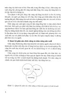
Figure 1.10
BR 700 industrial cleaning robot (left) and the RoboCleaner RC 3000 consumer robot developed and
sold by Alfred Kärcher GmbH & Co., Germany. The navigation system of BR 700 is based on a very
sophisticated sonar system and a gyro. The RoboCleaner RC 3000 covers badly soiled areas with a
special driving strategy until it is really clean. Optical sensors measure the degree of pollution of the
aspirated air (). © Alfred Kärcher GmbH & Co.
Introduction 7
Figure 1.11
PIONEER is a modular mobile robot offering various options like a gripper or an on-board camera.
It is equipped with a sophisticated navigation library developed at SRI, Stanford, CA (Reprinted with
permission from ActivMedia Robotics, ).
Figure 1.12
B21 of iRobot is a sophisticated mobile robot with up to three Intel Pentium processors on board. It
has a large variety of sensors for high-performance navigation tasks (
© iRobot Inc.
8 Chapter 1
For example, AGV (autonomous guided vehicle) robots (figure 1.8) autonomously
deliver parts between various assembly stations by following special electrical guidewires
using a custom sensor. The Helpmate service robot transports food and medication
throughout hospitals by tracking the position of ceiling lights, which are manually specified
to the robot beforehand (figure 1.9). Several companies have developed autonomous clean-
ing robots, mainly for large buildings (figure 1.10). One such cleaning robot is in use at the
Paris Metro. Other specialized cleaning robots take advantage of the regular geometric pat-
tern of aisles in supermarkets to facilitate the localization and navigation tasks.
Research into high-level questions of cognition, localization, and navigation can be per-
formed using standard research robot platforms that are tuned to the laboratory environ-
ment. This is one of the largest current markets for mobile robots. Various mobile robot
platforms are available for programming, ranging in terms of size and terrain capability.
The most popular research robots are those of ActivMedia Robotics, K-Team SA, and I-
Robot (figures 1.11, 1.12, 1.13) and also very small robots like the Alice from EPFL (Swiss
Federal Institute of Technology at Lausanne) (figure 1.14).
Although mobile robots have a broad set of applications and markets as summarized
above, there is one fact that is true of virtually every successful mobile robot: its design
involves the integration of many different bodies of knowledge. No mean feat, this makes
mobile robotics as interdisciplinary a field as there can be. To solve locomotion problems,
the mobile roboticist must understand mechanism and kinematics; dynamics and control
theory. To create robust perceptual systems, the mobile roboticist must leverage the fields
of signal analysis and specialized bodies of knowledge such as computer vision to properly
Figure 1.13
KHEPERA is a small mobile robot for research and education. It is only about 60 mm in diameter.
Various additional modules such as cameras and grippers are available. More then 700 units had
already been sold by the end of 1998. KHEPERA is manufactured and distributed by K-Team SA,
Switzerland (). © K-Team SA.
Introduction 9
employ a multitude of sensor technologies. Localization and navigation demand knowl-
edge of computer algorithms, information theory, artificial intelligence, and probability
theory.
Figure 1.15 depicts an abstract control scheme for mobile robot systems that we will use
throughout this text. This figure identifies many of the main bodies of knowledge associ-
ated with mobile robotics.
This book provides an introduction to all aspects of mobile robotics, including software
and hardware design considerations, related technologies, and algorithmic techniques. The
intended audience is broad, including both undergraduate and graduate students in intro-
ductory mobile robotics courses, as well as individuals fascinated by the field. While not
absolutely required, a familiarity with matrix algebra, calculus, probability theory, and
computer programming will significantly enhance the reader’s experience.
Mobile robotics is a large field, and this book focuses not on robotics in general, nor on
mobile robot applications, but rather on mobility itself. From mechanism and perception to
localization and navigation, this book focuses on the techniques and technologies that
enable robust mobility.
Clearly, a useful, commercially viable mobile robot does more than just move. It pol-
ishes the supermarket floor, keeps guard in a factory, mows the golf course, provides tours
in a museum, or provides guidance in a supermarket. The aspiring mobile roboticist will
start with this book, but quickly graduate to course work and research specific to the desired
application, integrating techniques from fields as disparate as human-robot interaction,
computer vision, and speech understanding.
Figure 1.14
Alice is one of the smallest fully autonomous robots. It is approximately 2x2x2cm, it has an auton-
omy of about 8 hours and uses infrared distance sensors, tactile whiskers, or even a small camera for
navigation [54].
10 Chapter 1
1.2 An Overview of the Book
This book introduces the different aspects of a robot in modules, much like the modules
shown in figure 1.15. Chapters 2 and 3 focus on the robot’s low-level locomotive ability.
Chapter 4 presents an in-depth view of perception. Then, Chapters 5 and 6 take us to the
higher-level challenges of localization and even higher-level cognition, specifically the
ability to navigate robustly. Each chapter builds upon previous chapters, and so the reader
is encouraged to start at the beginning, even if their interest is primarily at the high level.
Robotics is peculiar in that solutions to high-level challenges are most meaningful only in
the context of a solid understanding of the low-level details of the system.
Chapter 2, “Locomotion”, begins with a survey of the most popular mechanisms that
enable locomotion: wheels and legs. Numerous robotic examples demonstrate the particu-
Figure 1.15
Reference control scheme for mobile robot systems used throughout this book.
Raw data
Environment Model
Local Map
“Position”
Global Map
Actuator Commands
Sensing
Acting
Information
Extraction and
Interpretation
Path
Execution
Cognition
Path Planing
Knowledge,
Data Base
Mission
Commands
Path
Real World
Environment
Localization
Map Building
Motion Control
P
erception
Introduction 11
lar talents of each form of locomotion. But designing a robot’s locomotive system properly
requires the ability to evaluate its overall motion capabilities quantitatively. Chapter 3,
“Mobile Robot Kinematics”, applies principles of kinematics to the whole robot, beginning
with the kinematic contribution of each wheel and graduating to an analysis of robot
maneuverability enabled by each mobility mechanism configuration.
The greatest single shortcoming in conventional mobile robotics is, without doubt, per-
ception: mobile robots can travel across much of earth’s man-made surfaces, but they
cannot perceive the world nearly as well as humans and other animals. Chapter 4, “Percep-
tion”, begins a discussion of this challenge by presenting a clear language for describing
the performance envelope of mobile robot sensors. With this language in hand, chapter 4
goes on to present many of the off-the-shelf sensors available to the mobile roboticist,
describing their basic principles of operation as well as their performance limitations. The
most promising sensor for the future of mobile robotics is vision, and chapter 4 includes an
overview of the theory of operation and the limitations of both charged coupled device
(CCD) and complementary metal oxide semiconductor (CMOS) sensors.
But perception is more than sensing. Perception is also the interpretation of sensed data
in meaningful ways. The second half of chapter 4 describes strategies for feature extraction
that have been most useful in mobile robotics applications, including extraction of geomet-
ric shapes from range-based sensing data, as well as landmark and whole-image analysis
using vision-based sensing.
Armed with locomotion mechanisms and outfitted with hardware and software for per-
ception, the mobile robot can move and perceive the world. The first point at which mobil-
ity and sensing must meet is localization: mobile robots often need to maintain a sense of
position. Chapter 5, “Mobile Robot Localization”, describes approaches that obviate the
need for direct localization, then delves into fundamental ingredients of successful local-
ization strategies: belief representation and map representation. Case studies demonstrate
various localization schemes, including both Markov localization and Kalman filter local-
ization. The final part of chapter 5 is devoted to a discussion of the challenges and most
promising techniques for mobile robots to autonomously map their surroundings.
Mobile robotics is so young a discipline that it lacks a standardized architecture. There
is as yet no established robot operating system. But the question of architecture is of para-
mount importance when one chooses to address the higher-level competences of a mobile
robot: how does a mobile robot navigate robustly from place to place, interpreting data,
localizing and controlling its motion all the while? For this highest level of robot compe-
tence, which we term navigation competence, there are numerous mobile robots that show-
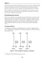
case particular architectural strategies. Chapter 6, “Planning and Navigation”, surveys the
state of the art of robot navigation, showing that today’s various techniques are quite sim-
ilar, differing primarily in the manner in which they decompose the problem of robot con-
12 Chapter 1
trol. But first, chapter 6 addresses two skills that a competent, navigating robot usually must
demonstrate: obstacle avoidance and path planning.
There is far more to know about the cross-disciplinary field of mobile robotics than can
be contained in a single book. We hope, though, that this broad introduction will place the
reader in the context of mobile robotics’ collective wisdom. This is only the beginning, but,
with luck, the first robot you program or build will have only good things to say about you.
2 Locomotion
2.1 Introduction
A mobile robot needs locomotion mechanisms that enable it to move unbounded through-
out its environment. But there are a large variety of possible ways to move, and so the selec-
tion of a robot’s approach to locomotion is an important aspect of mobile robot design. In
the laboratory, there are research robots that can walk, jump, run, slide, skate, swim, fly,
and, of course, roll. Most of these locomotion mechanisms have been inspired by their bio-
logical counterparts (see figure 2.1).
There is, however, one exception: the actively powered wheel is a human invention that
achieves extremely high efficiency on flat ground. This mechanism is not completely for-
eign to biological systems. Our bipedal walking system can be approximated by a rolling
polygon, with sides equal in length to the span of the step (figure 2.2). As the step size
decreases, the polygon approaches a circle or wheel. But nature did not develop a fully
rotating, actively powered joint, which is the technology necessary for wheeled locomo-
tion.
Biological systems succeed in moving through a wide variety of harsh environments.
Therefore it can be desirable to copy their selection of locomotion mechanisms. However,
replicating nature in this regard is extremely difficult for several reasons. To begin with,
mechanical complexity is easily achieved in biological systems through structural replica-
tion. Cell division, in combination with specialization, can readily produce a millipede with
several hundred legs and several tens of thousands of individually sensed cilia. In man-
made structures, each part must be fabricated individually, and so no such economies of
scale exist. Additionally, the cell is a microscopic building block that enables extreme min-
iaturization. With very small size and weight, insects achieve a level of robustness that we
have not been able to match with human fabrication techniques. Finally, the biological
energy storage system and the muscular and hydraulic activation systems used by large ani-
mals and insects achieve torque, response time, and conversion efficiencies that far exceed
similarly scaled man-made systems.
d
14 Chapter 2
Owing to these limitations, mobile robots generally locomote either using wheeled
mechanisms, a well-known human technology for vehicles, or using a small number of
articulated legs, the simplest of the biological approaches to locomotion (see figure 2.2).
In general, legged locomotion requires higher degrees of freedom and therefore greater
mechanical complexity than wheeled locomotion. Wheels, in addition to being simple, are
extremely well suited to flat ground. As figure 2.3 depicts, on flat surfaces wheeled loco-
motion is one to two orders of magnitude more efficient than legged locomotion. The rail-
way is ideally engineered for wheeled locomotion because rolling friction is minimized on
a hard and flat steel surface. But as the surface becomes soft, wheeled locomotion accumu-
lates inefficiencies due to rolling friction whereas legged locomotion suffers much less
because it consists only of point contacts with the ground. This is demonstrated in figure
2.3 by the dramatic loss of efficiency in the case of a tire on soft ground.
Figure 2.1
Locomotion mechanisms used in biological systems.
Flow in
Crawl
Sliding
Running
Jumping
Walking
Type of motion
Resistance to motion Basic kinematics of motion
Hydrodynamic forces
Friction forces
Friction forces
Loss of kinetic energy
Loss of kinetic energy
Gravitational forces
Rolling of a
Oscillatory
of a multi-link
Transverse vibration
Longitudinal vibration
Eddies
a Channel
polygon
(see figure 2.2)
movement
pendulum
Oscillatory
of a multi-link
movement
pendulum
Locomotion 15
Figure 2.2
A biped walking system can be approximated by a rolling polygon, with sides equal in length d to the
span of the step. As the step size decreases, the polygon approaches a circle or wheel with the radius l.
h
l
O
αα
d
Figure 2.3
Specific power versus attainable speed of various locomotion mechanisms [33].
1
10 100
100
10
1
0.1
unit power (hp/ton)
speed (miles/hour)
cr
aw
l
i
ng/
s
liding
r
unni
ng
t
i
re
on
sof
t
gr
ound
w
alkin
g
railway
w
hee
l
f
l
o
w
16 Chapter 2
In effect, the efficiency of wheeled locomotion depends greatly on environmental qual-
ities, particularly the flatness and hardness of the ground, while the efficiency of legged
locomotion depends on the leg mass and body mass, both of which the robot must support
at various points in a legged gait.
It is understandable therefore that nature favors legged locomotion, since locomotion
systems in nature must operate on rough and unstructured terrain. For example, in the case
of insects in a forest the vertical variation in ground height is often an order of magnitude
greater than the total height of the insect. By the same token, the human environment fre-
quently consists of engineered, smooth surfaces, both indoors and outdoors. Therefore, it
is also understandable that virtually all industrial applications of mobile robotics utilize
some form of wheeled locomotion. Recently, for more natural outdoor environments, there
has been some progress toward hybrid and legged industrial robots such as the forestry
robot shown in figure 2.4.
In the section 2.1.1, we present general considerations that concern all forms of mobile
robot locomotion. Following this, in sections 2.2 and 2.3, we present overviews of legged
locomotion and wheeled locomotion techniques for mobile robots.
2.1.1 Key issues for locomotion
Locomotion is the complement of manipulation. In manipulation, the robot arm is fixed but
moves objects in the workspace by imparting force to them. In locomotion, the environ-
ment is fixed and the robot moves by imparting force to the environment. In both cases, the
scientific basis is the study of actuators that generate interaction forces, and mechanisms
Figure 2.4
RoboTrac, a hybrid wheel-leg vehicle for rough terrain [130].
Locomotion 17
that implement desired kinematic and dynamic properties. Locomotion and manipulation
thus share the same core issues of stability, contact characteristics, and environmental type:
• stability
- number and geometry of contact points
- center of gravity
- static/dynamic stability
- inclination of terrain
• characteristics of contact
- contact point/path size and shape
- angle of contact
- friction
• type of environment
- structure
- medium, (e.g. water, air, soft or hard ground)
A theoretical analysis of locomotion begins with mechanics and physics. From this start-
ing point, we can formally define and analyze all manner of mobile robot locomotion sys-
tems. However, this book focuses on the mobile robot navigation problem, particularly
stressing perception, localization, and cognition. Thus we will not delve deeply into the
physical basis of locomotion. Nevertheless, the two remaining sections in this chapter
present overviews of issues in legged locomotion [33] and wheeled locomotion. Then,
chapter 3 presents a more detailed analysis of the kinematics and control of wheeled mobile
robots.
2.2 Legged Mobile Robots
Legged locomotion is characterized by a series of point contacts between the robot and the
ground. The key advantages include adaptability and maneuverability in rough terrain.
Because only a set of point contacts is required, the quality of the ground between those
points does not matter so long as the robot can maintain adequate ground clearance. In addi-
tion, a walking robot is capable of crossing a hole or chasm so long as its reach exceeds the
width of the hole. A final advantage of legged locomotion is the potential to manipulate
objects in the environment with great skill. An excellent insect example, the dung beetle, is
capable of rolling a ball while locomoting by way of its dexterous front legs.
The main disadvantages of legged locomotion include power and mechanical complex-
ity. The leg, which may include several degrees of freedom, must be capable of sustaining
part of the robot’s total weight, and in many robots must be capable of lifting and lowering
the robot. Additionally, high maneuverability will only be achieved if the legs have a suf-
ficient number of degrees of freedom to impart forces in a number of different directions.
18 Chapter 2
2.2.1 Leg configurations and stability
Because legged robots are biologically inspired, it is instructive to examine biologically
successful legged systems. A number of different leg configurations have been successful
in a variety of organisms (figure 2.5). Large animals, such as mammals and reptiles, have
four legs, whereas insects have six or more legs. In some mammals, the ability to walk on
only two legs has been perfected. Especially in the case of humans, balance has progressed
to the point that we can even jump with one leg
1
. This exceptional maneuverability comes
at a price: much more complex active control to maintain balance.
In contrast, a creature with three legs can exhibit a static, stable pose provided that it can
ensure that its center of gravity is within the tripod of ground contact. Static stability, dem-
onstrated by a three-legged stool, means that balance is maintained with no need for
motion. A small deviation from stability (e.g., gently pushing the stool) is passively cor-
rected toward the stable pose when the upsetting force stops.
But a robot must be able to lift its legs in order to walk. In order to achieve static walk-
ing, a robot must have at least six legs. In such a configuration, it is possible to design a gait
in which a statically stable tripod of legs is in contact with the ground at all times (figure
2.8).
Insects and spiders are immediately able to walk when born. For them, the problem of
balance during walking is relatively simple. Mammals, with four legs, cannot achieve static
walking, but are able to stand easily on four legs. Fauns, for example, spend several minutes
attempting to stand before they are able to do so, then spend several more minutes learning
to walk without falling. Humans, with two legs, cannot even stand in one place with static
stability. Infants require months to stand and walk, and even longer to learn to jump, run,
and stand on one leg.
1. In child development, one of the tests used to determine if the child is acquiring advanced loco-
motion skills is the ability to jump on one leg.
Figure 2.5
Arrangement of the legs of various animals.
mammals reptiles insects
two or four legs four legs six legs
Locomotion 19
There is also the potential for great variety in the complexity of each individual leg.
Once again, the biological world provides ample examples at both extremes. For instance,
in the case of the caterpillar, each leg is extended using hydraulic pressure by constricting
the body cavity and forcing an increase in pressure, and each leg is retracted longitudinally
by relaxing the hydraulic pressure, then activating a single tensile muscle that pulls the leg
in toward the body. Each leg has only a single degree of freedom, which is oriented longi-
tudinally along the leg. Forward locomotion depends on the hydraulic pressure in the body,
which extends the distance between pairs of legs. The caterpillar leg is therefore mechani-
cally very simple, using a minimal number of extrinsic muscles to achieve complex overall
locomotion.
At the other extreme, the human leg has more than seven major degrees of freedom,
combined with further actuation at the toes. More than fifteen muscle groups actuate eight
complex joints.
In the case of legged mobile robots, a minimum of two degrees of freedom is generally
required to move a leg forward by lifting the leg and swinging it forward. More common is
the addition of a third degree of freedom for more complex maneuvers, resulting in legs
such as those shown in figure 2.6. Recent successes in the creation of bipedal walking
robots have added a fourth degree of freedom at the ankle joint. The ankle enables more
consistent ground contact by actuating the pose of the sole of the foot.
In general, adding degrees of freedom to a robot leg increases the maneuverability of the
robot, both augmenting the range of terrains on which it can travel and the ability of the
robot to travel with a variety of gaits. The primary disadvantages of additional joints and
actuators are, of course, energy, control, and mass. Additional actuators require energy and
control, and they also add to leg mass, further increasing power and load requirements on
existing actuators.
Figure 2.6
Two examples of legs with three degrees of freedom.
θ
hip flexion angle (ψ)
hip abduction angle (θ)
knee flexion angle (ϕ)
ϕ
ψ
abduction-adduction
upper thigh link
lower thigh link
main drive
lift
shank link
20 Chapter 2
In the case of a multilegged mobile robot, there is the issue of leg coordination for loco-
motion, or gait control. The number of possible gaits depends on the number of legs [33].
The gait is a sequence of lift and release events for the individual legs. For a mobile robot
with legs, the total number of possible events for a walking machine is
(2.1)
For a biped walker legs, the number of possible events is
(2.2)
k
N
Figure 2.7
Two gaits with four legs. Because this robot has fewer than six legs, static walking is not generally
possible.
changeover walking galloping
free fly
N
2
k
1–()!=
k
2=
N
N
2
k
1–()!3!321⋅⋅ 6====
Locomotion 21
The six different events are
1. lift right leg;
2. lift left leg;
3. release right leg;
4. release left leg;
5. lift both legs together;
6. release both legs together.
Of course, this quickly grows quite large. For example, a robot with six legs has far more
gaits theoretically:
(2.3)
Figures 2.7 and 2.8 depict several four-legged gaits and the static six-legged tripod gait.
2.2.2 Examples of legged robot locomotion
Although there are no high-volume industrial applications to date, legged locomotion is an
important area of long-term research. Several interesting designs are presented below,
beginning with the one-legged robot and finishing with six-legged robots. For a very good
overview of climbing and walking robots, see />2.2.2.1 One leg
The minimum number of legs a legged robot can have is, of course, one. Minimizing the
number of legs is beneficial for several reasons. Body mass is particularly important to
walking machines, and the single leg minimizes cumulative leg mass. Leg coordination is
required when a robot has several legs, but with one leg no such coordination is needed.
Perhaps most importantly, the one-legged robot maximizes the basic advantage of legged
locomotion: legs have single points of contact with the ground in lieu of an entire track, as
with wheels. A single-legged robot requires only a sequence of single contacts, making it
amenable to the roughest terrain. Furthermore, a hopping robot can dynamically cross a gap
that is larger than its stride by taking a running start, whereas a multilegged walking robot
that cannot run is limited to crossing gaps that are as large as its reach.
The major challenge in creating a single-legged robot is balance. For a robot with one
leg, static walking is not only impossible but static stability when stationary is also impos-
sible. The robot must actively balance itself by either changing its center of gravity or by
imparting corrective forces. Thus, the successful single-legged robot must be dynamically
stable.
N
11! 3991680
0
==
22 Chapter 2
Figure 2.9 shows the Raibert hopper [28, 124], one of the most well-known single-
legged hopping robots created. This robot makes continuous corrections to body attitude
and to robot velocity by adjusting the leg angle with respect to the body. The actuation is
hydraulic, including high-power longitudinal extension of the leg during stance to hop back
into the air. Although powerful, these actuators require a large, off-board hydraulic pump
to be connected to the robot at all times.
Figure 2.10 shows a more energy-efficient design developed more recently [46]. Instead
of supplying power by means of an off-board hydraulic pump, the bow leg hopper is
designed to capture the kinetic energy of the robot as it lands, using an efficient bow spring
leg. This spring returns approximately 85% of the energy, meaning that stable hopping
requires only the addition of 15% of the required energy on each hop. This robot, which is
constrained along one axis by a boom, has demonstrated continuous hopping for 20 minutes
using a single set of batteries carried on board the robot. As with the Raibert hopper, the
bow leg hopper controls velocity by changing the angle of the leg to the body at the hip
joint.
Figure 2.8
Static walking with six legs. A tripod formed by three legs always exists.
Locomotion 23
Figure 2.9
The Raibert hopper [28, 124]. Image courtesy of the LegLab and Marc Raibert. © 1983.
Figure 2.10
The 2D single bow leg hopper [46]. Image courtesy of H. Benjamin Brown and Garth Zeglin, CMU.
24 Chapter 2
The paper of Ringrose [125] demonstrates the very important duality of mechanics and
controls as applied to a single-legged hopping machine. Often clever mechanical design
can perform the same operations as complex active control circuitry. In this robot, the phys-
ical shape of the foot is exactly the right curve so that when the robot lands without being
perfectly vertical, the proper corrective force is provided from the impact, making the robot
vertical by the next landing. This robot is dynamically stable, and is furthermore passive.
The correction is provided by physical interactions between the robot and its environment,
with no computer or any active control in the loop.
2.2.2.2 Two legs (biped)
A variety of successful bipedal robots have been demonstrated over the past ten years. Two
legged robots have been shown to run, jump, travel up and down stairways, and even do
aerial tricks such as somersaults. In the commercial sector, both Honda and Sony have
made significant advances over the past decade that have enabled highly capable bipedal
robots. Both companies designed small, powered joints that achieve power-to-weight per-
formance unheard of in commercially available servomotors. These new “intelligent”
servos provide not only strong actuation but also compliant actuation by means of torque
sensing and closed-loop control.
Figure 2.11
The Sony SDR-4X II, © 2003 Sony Corporation.
Specifications:
Weight: 7 kg
Height: 58 cm
Neck DOF: 4
Body DOF: 2
Arm DOF: 2 x 5
Legs DOF: 2 x 6
Five-finger Hands
Locomotion 25
The Sony Dream Robot, model SDR-4X II, is shown in figure 2.11. This current model
is the result of research begun in 1997 with the basic objective of motion entertainment and
communication entertainment (i.e., dancing and singing). This robot with thirty-eight
degrees of freedom has seven microphones for fine localization of sound, image-based
person recognition, on-board miniature stereo depth-map reconstruction, and limited
speech recognition. Given the goal of fluid and entertaining motion, Sony spent consider-
able effort designing a motion prototyping application system to enable their engineers to
script dances in a straightforward manner. Note that the SDR-4X II is relatively small,
standing at 58 cm and weighing only 6.5 kg.
The Honda humanoid project has a significant history but, again, has tackled the very
important engineering challenge of actuation. Figure 2.12 shows model P2, which is an
immediate predecessor to the most recent Asimo model (advanced step in innovative
mobility). Note from this picture that the Honda humanoid is much larger than the SDR-
4X at 120 cm tall and 52 kg. This enables practical mobility in the human world of stairs
and ledges while maintaining a nonthreatening size and posture. Perhaps the first robot to
famously demonstrate biomimetic bipedal stair climbing and descending, these Honda
humanoid series robots are being designed not for entertainment purposes but as human
aids throughout society. Honda refers, for instance, to the height of Asimo as the minimum
height which enables it to nonetheless manage operation of the human world, for instance,
control of light switches.
Figure 2.12
The humanoid robot P2 from Honda, Japan. © Honda Motor Corporation.
Specifications:
Maximum speed: 2 km/h
Autonomy: 15 min
Weight: 210 kg
Height: 1.82 m
Leg DOF: 2 x 6
Arm DOF: 2 x 7