MIT.Press.Introduction.to.Autonomous.Mobile.Robots Part 3 pdf
Bạn đang xem bản rút gọn của tài liệu. Xem và tải ngay bản đầy đủ của tài liệu tại đây (823.76 KB, 20 trang )
26 Chapter 2
An important feature of bipedal robots is their anthropomorphic shape. They can be built
to have the same approximate dimensions as humans, and this makes them excellent vehi-
cles for research in human-robot interaction. WABIAN is a robot built at Waseda Univer-
sities Japan (figure 2.13) for just such research [75]. WABIAN is designed to emulate
human motion, and is even designed to dance like a human.
Bipedal robots can only be statically stable within some limits, and so robots such as P2
and WABIAN generally must perform continuous balance-correcting servoing even when
standing still. Furthermore, each leg must have sufficient capacity to support the full weight
of the robot. In the case of four-legged robots, the balance problem is facilitated along with
the load requirements of each leg. An elegant design of a biped robot is the Spring Fla-
mingo of MIT (figure 2.14). This robot inserts springs in series with the leg actuators to
achieve a more elastic gait. Combined with “kneecaps” that limit knee joint angles, the Fla-
mingo achieves surprisingly biomimetic motion.
2.2.2.3 Four legs (quadruped)
Although standing still on four legs is passively stable, walking remains challenging
because to remain stable the robot’s center of gravity must be actively shifted during the
Figure 2.13
The humanoid robot WABIAN-RIII at Waseda University in Japan [75]. Image courtesy of Atsuo
Takanishi, Waseda University.
Specifications:
Weight: 131 [kg]
Height: 1.88 [m]
DOF in total: 43
Lower Limbs: 2 x 6
Trunk: 3
Arms: 2 x 10
Neck: 4
Eyes: 2 x 2
Locomotion 27
gait. Sony recently invested several million dollars to develop a four-legged robot called
AIBO (figure 2.15). To create this robot, Sony produced both a new robot operating system
that is near real-time and new geared servomotors that are of sufficiently high torque to sup-
port the robot, yet back drivable for safety. In addition to developing custom motors and
software, Sony incorporated a color vision system that enables AIBO to chase a brightly
colored ball. The robot is able to function for at most one hour before requiring recharging.
Early sales of the robot have been very strong, with more than 60,000 units sold in the first
year. Nevertheless, the number of motors and the technology investment behind this robot
dog resulted in a very high price of approximately $1500.
Four-legged robots have the potential to serve as effective artifacts for research in
human-robot interaction (figure 2.16). Humans can treat the Sony robot, for example, as a
pet and might develop an emotional relationship similar to that between man and dog. Fur-
thermore, Sony has designed AIBO’s walking style and general behavior to emulate learn-
ing and maturation, resulting in dynamic behavior over time that is more interesting for the
owner who can track the changing behavior. As the challenges of high energy storage and
motor technology are solved, it is likely that quadruped robots much more capable than
AIBO will become common throughout the human environment.
2.2.2.4 Six legs (hexapod)
Six-legged configurations have been extremely popular in mobile robotics because of their
static stability during walking, thus reducing the control complexity (figures 2.17 and 1.3).
Figure 2.14
The Spring Flamingo developed at MIT [123]. Image courtesy of Jerry Pratt, MIT Leg Laboratory.
28 Chapter 2
In most cases, each leg has three degrees of freedom, including hip flexion, knee flexion,
and hip abduction (see figure 2.6). Genghis is a commercially available hobby robot that
has six legs, each of which has two degrees of freedom provided by hobby servos (figure
2.18). Such a robot, which consists only of hip flexion and hip abduction, has less maneu-
verability in rough terrain but performs quite well on flat ground. Because it consists of a
straightforward arrangement of servomotors and straight legs, such robots can be readily
built by a robot hobbyist.
Insects, which are arguably the most successful locomoting creatures on earth, excel at
traversing all forms of terrain with six legs, even upside down. Currently, the gap between
the capabilities of six-legged insects and artificial six-legged robots is still quite large.
Interestingly, this is not due to a lack of sufficient numbers of degrees of freedom on the
robots. Rather, insects combine a small number of active degrees of freedom with passive
Figure 2.15
AIBO, the artificial dog from Sony, Japan.
1 Stereo microphone: Allows AIBO to pick
up surrounding sounds.
2 Head sensor: Senses when a person taps or
pets AIBO on the head.
3 Mode indicator: Shows AIBO’s operation
mode.
4 Eye lights: These light up in blue-green or
red to indicate AIBO’s emotional state.
5 Color camera: Allows AIBO to search for
objects and recognize them by color and
movement.
6 Speaker: Emits various musical tones and
sound effects.
7 Chin sensor: Senses when a person touches
AIBO on the chin.
8 Pause button: Press to activate AIBO or to
pause AIBO.
9 Chest light: Gives information about the
status of the robot.
10 Paw sensors: Located on the bottom of each
paw.
11 Tail light: Lights up blue or orange to show
AIBO’s emotional state.
12 Back sensor: Senses when a person touches
AIBO on the back.
ERS-210
© 2000 Sony Corporation
ERS-110
© 1999 Sony Corporation
Locomotion 29
Figure 2.16
Titan VIII, a quadruped robot developed at Tokyo Institute of Technology.
( © Tokyo Institute of Technology.
Specifications:
Weight:1 9 kg
Height: 0.25 m
DOF: 4 x 3
Figure 2.17
Lauron II, a hexapod platform developed at the University of Karlsruhe, Germany.
© University of Karlsruhe.
Specifications:
Maximum speed: 0.5 m/s
Weight:1 6 kg
Height: 0.3 m
Length: 0.7 m
No. of legs: 6
DOF in total: 6 x 3
Power consumption:10 W
30 Chapter 2
structures, such as microscopic barbs and textured pads, that increase the gripping strength
of each leg significantly. Robotic research into such passive tip structures has only recently
begun. For example, a research group is attempting to re-create the complete mechanical
function of the cockroach leg [65].
It is clear from the above examples that legged robots have much progress to make
before they are competitive with their biological equivalents. Nevertheless, significant
gains have been realized recently, primarily due to advances in motor design. Creating
actuation systems that approach the efficiency of animal muscles remains far from the
reach of robotics, as does energy storage with the energy densities found in organic life
forms.
2.3 Wheeled Mobile Robots
The wheel has been by far the most popular locomotion mechanism in mobile robotics and
in man-made vehicles in general. It can achieve very good efficiencies, as demonstrated in
figure 2.3, and does so with a relatively simple mechanical implementation.
In addition, balance is not usually a research problem in wheeled robot designs, because
wheeled robots are almost always designed so that all wheels are in ground contact at all
times. Thus, three wheels are sufficient to guarantee stable balance, although, as we shall
see below, two-wheeled robots can also be stable. When more than three wheels are used,
a suspension system is required to allow all wheels to maintain ground contact when the
robot encounters uneven terrain.
Instead of worrying about balance, wheeled robot research tends to focus on the prob-
lems of traction and stability, maneuverability, and control: can the robot wheels provide
Figure 2.18
Genghis, one of the most famous walking robots from MIT, uses hobby servomotors as its actuators
( © MIT AI Lab.
Locomotion 31
sufficient traction and stability for the robot to cover all of the desired terrain, and does the
robot’s wheeled configuration enable sufficient control over the velocity of the robot?
2.3.1 Wheeled locomotion: the design space
As we shall see, there is a very large space of possible wheel configurations when one con-
siders possible techniques for mobile robot locomotion. We begin by discussing the wheel
in detail, as there are a number of different wheel types with specific strengths and weak-
nesses. Then, we examine complete wheel configurations that deliver particular forms of
locomotion for a mobile robot.
2.3.1.1 Wheel design
There are four major wheel classes, as shown in figure 2.19. They differ widely in their
kinematics, and therefore the choice of wheel type has a large effect on the overall kinemat-
ics of the mobile robot. The standard wheel and the castor wheel have a primary axis of
rotation and are thus highly directional. To move in a different direction, the wheel must be
steered first along a vertical axis. The key difference between these two wheels is that the
standard wheel can accomplish this steering motion with no side effects, as the center of
rotation passes through the contact patch with the ground, whereas the castor wheel rotates
around an offset axis, causing a force to be imparted to the robot chassis during steering.
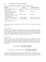
Figure 2.19
The four basic wheel types. (a) Standard wheel: two degrees of freedom; rotation around the (motor-
ized) wheel axle and the contact point.(b) castor wheel: two degrees of freedom; rotation around an
offset steering joint. (c) Swedish wheel: three degrees of freedom; rotation around the (motorized)
wheel axle, around the rollers, and around the contact point. (d) Ball or spherical wheel: realization
technically difficult.
a)
Swedish 90° Swedish 45°
Swedish 45°
b) c) d)
32 Chapter 2
The Swedish wheel and the spherical wheel are both designs that are less constrained by
directionality than the conventional standard wheel. The Swedish wheel functions as a
normal wheel, but provides low resistance in another direction as well, sometimes perpen-
dicular to the conventional direction, as in the Swedish 90, and sometimes at an intermedi-
ate angle, as in the Swedish 45. The small rollers attached around the circumference of the
wheel are passive and the wheel’s primary axis serves as the only actively powered joint.
The key advantage of this design is that, although the wheel rotation is powered only along
the one principal axis (through the axle), the wheel can kinematically move with very little
friction along many possible trajectories, not just forward and backward.
The spherical wheel is a truly omnidirectional wheel, often designed so that it may be
actively powered to spin along any direction. One mechanism for implementing this spher-
ical design imitates the computer mouse, providing actively powered rollers that rest
against the top surface of the sphere and impart rotational force.
Regardless of what wheel is used, in robots designed for all-terrain environments and in
robots with more than three wheels, a suspension system is normally required to maintain
wheel contact with the ground. One of the simplest approaches to suspension is to design
flexibility into the wheel itself. For instance, in the case of some four-wheeled indoor robots
that use castor wheels, manufacturers have applied a deformable tire of soft rubber to the
wheel to create a primitive suspension. Of course, this limited solution cannot compete with
a sophisticated suspension system in applications where the robot needs a more dynamic
suspension for significantly non flat terrain.
Figure 2.20
N
avlab I, the first autonomous highway vehicle that steers and controls the throttle using vision and
radar sensors [61]. Developed at CMU.
Locomotion 33
2.3.1.2 Wheel geometry
The choice of wheel types for a mobile robot is strongly linked to the choice of wheel
arrangement, or wheel geometry. The mobile robot designer must consider these two issues
simultaneously when designing the locomoting mechanism of a wheeled robot. Why do
wheel type and wheel geometry matter? Three fundamental characteristics of a robot are
governed by these choices: maneuverability, controllability, and stability.
Unlike automobiles, which are largely designed for a highly standardized environment
(the road network), mobile robots are designed for applications in a wide variety of situa-
tions. Automobiles all share similar wheel configurations because there is one region in the
design space that maximizes maneuverability, controllability, and stability for their stan-
dard environment: the paved roadway. However, there is no single wheel configuration that
maximizes these qualities for the variety of environments faced by different mobile robots.
So you will see great variety in the wheel configurations of mobile robots. In fact, few
robots use the Ackerman wheel configuration of the automobile because of its poor maneu-
verability, with the exception of mobile robots designed for the road system (figure 2.20).
Table 2.1 gives an overview of wheel configurations ordered by the number of wheels.
This table shows both the selection of particular wheel types and their geometric configu-
ration on the robot chassis. Note that some of the configurations shown are of little use in
mobile robot applications. For instance, the two-wheeled bicycle arrangement has moder-
ate maneuverability and poor controllability. Like a single-legged hopping machine, it can
never stand still. Nevertheless, this table provides an indication of the large variety of wheel
configurations that are possible in mobile robot design.
The number of variations in table 2.1 is quite large. However, there are important trends
and groupings that can aid in comprehending the advantages and disadvantages of each
configuration. Below, we identify some of the key trade-offs in terms of the three issues we
identified earlier: stability, maneuverability, and controllability.
2.3.1.3 Stability
Surprisingly, the minimum number of wheels required for static stability is two. As shown
above, a two-wheel differential-drive robot can achieve static stability if the center of mass
is below the wheel axle. Cye is a commercial mobile robot that uses this wheel configura-
tion (figure 2.21).
However, under ordinary circumstances such a solution requires wheel diameters that
are impractically large. Dynamics can also cause a two-wheeled robot to strike the floor
with a third point of contact, for instance, with sufficiently high motor torques from stand-
still. Conventionally, static stability requires a minimum of three wheels, with the addi-
tional caveat that the center of gravity must be contained within the triangle formed by the
ground contact points of the wheels. Stability can be further improved by adding more
wheels, although once the number of contact points exceeds three, the hyperstatic nature of
the geometry will require some form of flexible suspension on uneven terrain.
34 Chapter 2
Table 2.1
Wheel configurations for rolling vehicles
# of
wheels
Arrangement Description Typical examples
2 One steering wheel in the front,
one traction wheel in the rear
Bicycle, motorcycle
Two-wheel differential drive
with the center of mass (COM)
below the axle
Cye personal robot
3 Two-wheel centered differen-
tial drive with a third point of
contact
Nomad Scout, smartRob
EPFL
Two independently driven
wheels in the rear/front, 1
unpowered omnidirectional
wheel in the front/rear
Many indoor robots,
including the EPFL robots
Pygmalion and Alice
Two connected traction wheels
(differential) in rear, 1 steered
free wheel in front
Piaggio minitrucks
Two free wheels in rear, 1
steered traction wheel in front
Neptune (Carnegie Mellon
University), Hero-1
Three motorized Swedish or
spherical wheels arranged in a
triangle; omnidirectional move-
ment is possible
Stanford wheel
Tribolo EPFL,
Palm Pilot Robot Kit
(CMU)
Three synchronously motorized
and steered wheels; the orienta-
tion is not controllable
“Synchro drive”
Denning MRV-2, Geor-
gia Institute of Technol-
ogy, I-Robot B24, Nomad
200
Locomotion 35
4 Two motorized wheels in the
rear, 2 steered wheels in the
front; steering has to be differ-
ent for the 2 wheels to avoid
slipping/skidding.
Car with rear-wheel drive
Two motorized and steered
wheels in the front, 2 free
wheels in the rear; steering has
to be different for the 2 wheels
to avoid slipping/skidding.
Car with front-wheel drive
Four steered and motorized
wheels
Four-wheel drive, four-
wheel steering Hyperion
(CMU)
Two traction wheels (differen-
tial) in rear/front, 2 omnidirec-
tional wheels in the front/rear
Charlie (DMT-EPFL)
Four omnidirectional wheels Carnegie Mellon Uranus
Two-wheel differential drive
with 2 additional points of con-
tact
EPFL Khepera, Hyperbot
Chip
Four motorized and steered
castor wheels
Nomad XR4000
Table 2.1
Wheel configurations for rolling vehicles
# of
wheels
Arrangement Description Typical examples
36 Chapter 2
2.3.1.4 Maneuverability
Some robots are omnidirectional, meaning that they can move at any time in any direction
along the ground plane regardless of the orientation of the robot around its vertical
axis. This level of maneuverability requires wheels that can move in more than just one
direction, and so omnidirectional robots usually employ Swedish or spherical wheels that
are powered. A good example is Uranus, shown in figure 2.24. This robot uses four Swed-
ish wheels to rotate and translate independently and without constraints.
6 Two motorized and steered
wheels aligned in center, 1
omnidirectional wheel at each
corner
First
Two traction wheels (differen-
tial) in center, 1 omnidirec-
tional wheel at each corner
Terregator (Carnegie Mel-
lon University)
Icons for the each wheel type are as follows:
unpowered omnidirectional wheel (spherical, castor, Swedish);
motorized Swedish wheel (Stanford wheel);
unpowered standard wheel;
motorized standard wheel;
motorized and steered castor wheel;
steered standard wheel;
connected wheels.
Table 2.1
Wheel configurations for rolling vehicles
# of
wheels
Arrangement Description Typical examples
xy,()
Locomotion 37
In general, the ground clearance of robots with Swedish and spherical wheels is some-
what limited due to the mechanical constraints of constructing omnidirectional wheels. An
interesting recent solution to the problem of omnidirectional navigation while solving this
ground-clearance problem is the four-castor wheel configuration in which each castor
wheel is actively steered and actively translated. In this configuration, the robot is truly
omnidirectional because, even if the castor wheels are facing a direction perpendicular to
the desired direction of travel, the robot can still move in the desired direction by steering
these wheels. Because the vertical axis is offset from the ground-contact path, the result of
this steering motion is robot motion.
In the research community, other classes of mobile robots are popular which achieve
high maneuverability, only slightly inferior to that of the omnidirectional configurations.
In such robots, motion in a particular direction may initially require a rotational motion.
With a circular chassis and an axis of rotation at the center of the robot, such a robot can
spin without changing its ground footprint. The most popular such robot is the two-wheel
differential-drive robot where the two wheels rotate around the center point of the robot.
One or two additional ground contact points may be used for stability, based on the appli-
cation specifics.
In contrast to the above configurations, consider the Ackerman steering configuration
common in automobiles. Such a vehicle typically has a turning diameter that is larger than
the car. Furthermore, for such a vehicle to move sideways requires a parking maneuver con-
sisting of repeated changes in direction forward and backward. Nevertheless, Ackerman
steering geometries have been especially popular in the hobby robotics market, where a
robot can be built by starting with a remote control racecar kit and adding sensing and
autonomy to the existing mechanism. In addition, the limited maneuverability of Ackerman
Figure 2.21
Cye, a commercially available domestic robot that can vacuum and make deliveries in the home, is
built by Aethon Inc. (). © Aethon Inc.
38 Chapter 2
steering has an important advantage: its directionality and steering geometry provide it with
very good lateral stability in high-speed turns.
2.3.1.5 Controllability
There is generally an inverse correlation between controllability and maneuverability. For
example, the omnidirectional designs such as the four-castor wheel configuration require
significant processing to convert desired rotational and translational velocities to individual
wheel commands. Furthermore, such omnidirectional designs often have greater degrees of
freedom at the wheel. For instance, the Swedish wheel has a set of free rollers along the
wheel perimeter. These degrees of freedom cause an accumulation of slippage, tend to
reduce dead-reckoning accuracy and increase the design complexity.
Controlling an omnidirectional robot for a specific direction of travel is also more diffi-
cult and often less accurate when compared to less maneuverable designs. For example, an
Ackerman steering vehicle can go straight simply by locking the steerable wheels and driv-
ing the drive wheels. In a differential-drive vehicle, the two motors attached to the two
wheels must be driven along exactly the same velocity profile, which can be challenging
considering variations between wheels, motors, and environmental differences. With four-
wheel omnidrive, such as the Uranus robot, which has four Swedish wheels, the problem is
even harder because all four wheels must be driven at exactly the same speed for the robot
to travel in a perfectly straight line.
In summary, there is no “ideal” drive configuration that simultaneously maximizes sta-
bility, maneuverability, and controllability. Each mobile robot application places unique
constraints on the robot design problem, and the designer’s task is to choose the most
appropriate drive configuration possible from among this space of compromises.
2.3.2 Wheeled locomotion: case studies
Below we describe four specific wheel configurations, in order to demonstrate concrete
applications of the concepts discussed above to mobile robots built for real-world activities.
2.3.2.1 Synchro drive
The synchro drive configuration (figure 2.22) is a popular arrangement of wheels in indoor
mobile robot applications. It is an interesting configuration because, although there are
three driven and steered wheels, only two motors are used in total. The one translation
motor sets the speed of all three wheels together, and the one steering motor spins all the
wheels together about each of their individual vertical steering axes. But note that the
wheels are being steered with respect to the robot chassis, and therefore there is no direct
way of reorienting the robot chassis. In fact, the chassis orientation does drift over time due
to uneven tire slippage, causing rotational dead-reckoning error.
Locomotion 39
Synchro drive is particularly advantageous in cases where omnidirectionality is sought.
So long as each vertical steering axis is aligned with the contact path of each tire, the robot
can always reorient its wheels and move along a new trajectory without changing its foot-
print. Of course, if the robot chassis has directionality and the designers intend to reorient
the chassis purposefully, then synchro drive is only appropriate when combined with an
independently rotating turret that attaches to the wheel chassis. Commercial research robots
such as the Nomadics 150 or the RWI B21r have been sold with this configuration
(figure 1.12).
In terms of dead reckoning, synchro drive systems are generally superior to true omni-
directional configurations but inferior to differential-drive and Ackerman steering systems.
There are two main reasons for this. First and foremost, the translation motor generally
drives the three wheels using a single belt. Because of to slop and backlash in the drive
train, whenever the drive motor engages, the closest wheel begins spinning before the fur-
thest wheel, causing a small change in the orientation of the chassis. With additional
changes in motor speed, these small angular shifts accumulate to create a large error in ori-
entation during dead reckoning. Second, the mobile robot has no direct control over the ori-
entation of the chassis. Depending on the orientation of the chassis, the wheel thrust can be
highly asymmetric, with two wheels on one side and the third wheel alone, or symmetric,
with one wheel on each side and one wheel straight ahead or behind, as shown in figure
2.22. The asymmetric cases result in a variety of errors when tire-ground slippage can
occur, again causing errors in dead reckoning of robot orientation.
Figure 2.22
Synchro drive: The robot can move in any direction; however, the orientation of the chassis is not
controllable.
wheel
s
t
e
e
r
i
n
g
b
e
l
t
d
r
i
v
e
b
e
l
t
drive motor
steering
steering pulley
driving pulley
wheel steering axis
motor
rolling axis
40 Chapter 2
2.3.2.2 Omnidirectional drive
As we will see later in section 3.4.2, omnidirectional movement is of great interest for com-
plete maneuverability. Omnidirectional robots that are able to move in any direction
() at any time are also holonomic (see section 3.4.2). They can be realized by either
using spherical, castor, or Swedish wheels. Three examples of such holonomic robots are
presented below.
Omnidirectional locomotion with three spherical wheels. The omnidirectional robot
depicted in figure 2.23 is based on three spherical wheels, each actuated by one motor. In
this design, the spherical wheels are suspended by three contact points, two given by spher-
ical bearings and one by a wheel connected to the motor axle. This concept provides excel-
lent maneuverability and is simple in design. However, it is limited to flat surfaces and
small loads, and it is quite difficult to find round wheels with high friction coefficients.
Omnidirectional locomotion with four Swedish wheels. The omnidirectional arrange-
ment depicted in figure 2.24 has been used successfully on several research robots, includ-
ing the Carnegie Mellon Uranus. This configuration consists of four Swedish 45-degree
wheels, each driven by a separate motor. By varying the direction of rotation and relative
speeds of the four wheels, the robot can be moved along any trajectory in the plane and,
even more impressively, can simultaneously spin around its vertical axis.
xyθ,,
Figure 2.23
The Tribolo designed at EPFL (Swiss Federal Institute of Technology, Lausanne, Switzerland. Left:
arrangement of spheric bearings and motors (bottom view). Right: Picture of the robot without the
spherical wheels (bottom view).
spheric bearing motor
Locomotion 41
For example, when all four wheels spin “forward” or “backward” the robot as a whole
moves in a straight line forward or backward, respectively. However, when one diagonal
pair of wheels is spun in the same direction and the other diagonal pair is spun in the oppo-
site direction, the robot moves laterally.
This four-wheel arrangement of Swedish wheels is not minimal in terms of control
motors. Because there are only three degrees of freedom in the plane, one can build a three-
wheel omnidirectional robot chassis using three Swedish 90-degree wheels as shown in
table 2.1. However, existing examples such as Uranus have been designed with four wheels
owing to capacity and stability considerations.
One application for which such omnidirectional designs are particularly amenable is
mobile manipulation. In this case, it is desirable to reduce the degrees of freedom of the
manipulator arm to save arm mass by using the mobile robot chassis motion for gross
motion. As with humans, it would be ideal if the base could move omnidirectionally with-
out greatly impacting the position of the manipulator tip, and a base such as Uranus can
afford precisely such capabilities.
Omnidirectional locomotion with four castor wheels and eight motors. Another solu-
tion for omnidirectionality is to use castor wheels. This is done for the Nomad XR4000
from Nomadic Technologies (fig. 2.25), giving it excellent maneuverability. Unfortu-
nately, Nomadic has ceased production of mobile robots.
The above three examples are drawn from table 2.1, but this is not an exhaustive list of
all wheeled locomotion techniques. Hybrid approaches that combine legged and wheeled
locomotion, or tracked and wheeled locomotion, can also offer particular advantages.
Below are two unique designs created for specialized applications.
Figure 2.24
The Carnegie Mellon Uranus robot, an omnidirectional robot with four powered-swedish 45 wheels.
42 Chapter 2
2.3.2.3 Tracked slip/skid locomotion
In the wheel configurations discussed above, we have made the assumption that wheels are
not allowed to skid against the surface. An alternative form of steering, termed slip/skid,
may be used to reorient the robot by spinning wheels that are facing the same direction at
different speeds or in opposite directions. The army tank operates this way, and the
Nanokhod (figure 2.26) is an example of a mobile robot based on the same concept.
Robots that make use of tread have much larger ground contact patches, and this can sig-
nificantly improve their maneuverability in loose terrain compared to conventional
wheeled designs. However, due to this large ground contact patch, changing the orientation
of the robot usually requires a skidding turn, wherein a large portion of the track must slide
against the terrain.
The disadvantage of such configurations is coupled to the slip/skid steering. Because of
the large amount of skidding during a turn, the exact center of rotation of the robot is hard
to predict and the exact change in position and orientation is also subject to variations
depending on the ground friction. Therefore, dead reckoning on such robots is highly inac-
curate. This is the trade-off that is made in return for extremely good maneuverability and
traction over rough and loose terrain. Furthermore, a slip/skid approach on a high-friction
surface can quickly overcome the torque capabilities of the motors being used. In terms of
power efficiency, this approach is reasonably efficient on loose terrain but extremely inef-
ficient otherwise.
Figure 2.25
The Nomad XR4000 from Nomadic Technologies had an arrangement of four castor wheels for holo-
nomic motion. All the castor wheels are driven and steered, thus requiring a precise synchronization
and coordination to obtain a precise movement in and . x
y
,θ
Locomotion 43
2.3.2.4 Walking wheels
Walking robots might offer the best maneuverability in rough terrain. However, they are
inefficient on flat ground and need sophisticated control. Hybrid solutions, combining the
adaptability of legs with the efficiency of wheels, offer an interesting compromise. Solu-
tions that passively adapt to the terrain are of particular interest for field and space robotics.
The Sojourner robot of NASA/JPL (see figure 1.2) represents such a hybrid solution, able
to overcome objects up to the size of the wheels. A more recent mobile robot design for
similar applications has recently been produced by EPFL (figure 2.27). This robot, called
Shrimp, has six motorized wheels and is capable of climbing objects up to two times its
wheel diameter [97, 133]. This enables it to climb regular stairs though the robot is even
smaller than the Sojourner. Using a rhombus configuration, the Shrimp has a steering wheel
in the front and the rear, and two wheels arranged on a bogie on each side. The front wheel
has a spring suspension to guarantee optimal ground contact of all wheels at any time. The
steering of the rover is realized by synchronizing the steering of the front and rear wheels
and the speed difference of the bogie wheels. This allows for high-precision maneuvers and
turning on the spot with minimum slip/skid of the four center wheels. The use of parallel
articulations for the front wheel and the bogies creates a virtual center of rotation at the
level of the wheel axis. This ensures maximum stability and climbing abilities even for very
low friction coefficients between the wheel and the ground.
Figure 2.26
The microrover Nanokhod, developed by von Hoerner & Sulger GmbH and the Max Planck Institute,
Mainz, for the European Space Agency (ESA), will probably go to Mars [138, 154].
44 Chapter 2
The climbing ability of the Shrimp is extraordinary in comparison to most robots of sim-
ilar mechanical complexity, owing much to the specific geometry and thereby the manner
in which the center of mass (COM) of the robot shifts with respect to the wheels over time.
In contrast, the Personal Rover demonstrates active COM shifting to climb ledges that are
also several times the diameter of its wheels, as demonstrated in figure 2.28. A majority of
the weight of the Personal Rover is borne at the upper end of its swinging boom. A dedi-
cated motor drives the boom to change the front/rear weight distribution in order to facili-
tate step-climbing. Because this COM-shifting scheme is active, a control loop must
explicitly decide how to move the boom during a climbing scenario. In this case the Per-
sonal Rover accomplished this closed-loop control by inferring terrain based on measure-
ments of current flowing to each independently driven wheel [66].
As mobile robotics research matures we find ourselves able to design more intricate
mechanical systems. At the same time, the control problems of inverse kinematics and
dynamics are now so readily conquered that these complex mechanics can in general be
controlled. So, in the near future, we can expect to see a great number of unique, hybrid
mobile robots that draw together advantages from several of the underlying locomotion
mechanisms that we have discussed in this chapter. They will each be technologically
impressive, and each will be designed as the expert robot for its particular environmental
niche.
Figure 2.27
Shrimp, an all-terrain robot with outstanding passive climbing abilities (EPFL [97, 133]).
Locomotion 45
Figure 2.28
The Personal Rover, demonstrating ledge climbing using active center-of-mass shifting.