Motion Control Theory Needed In The Implementation Of Practical Robotic Systems 2 Part 1 pot
Bạn đang xem bản rút gọn của tài liệu. Xem và tải ngay bản đầy đủ của tài liệu tại đây (32.67 KB, 8 trang )
Motion Control Theory Needed in the
Implementation of Practical Robotic Systems
James Mentz
Thesis submitted to the Faculty of the
Virginia Polytechnic Institute and State University
in partial fulfillment of the requirements for the degree of
Master of Science
in
Electrical Engineering
Hugh F. VanLandingham, Chair
Pushkin Kachroo
Richard W. Conners
April 4, 2000
Blacksburg, Virginia
Keywords: Motion Control, Robotics, Obstacle Avoidance, Navigation
Copyright 2000, James Mentz
Motion Control Theory Needed in the
Implementation of Practical Robotic Systems
James Mentz
(Abstract)
Two areas of expertise required in the production of industrial and commercial
robotics are motor control and obstacle navigation algorithms. This is especially true in
the field of autonomous robotic vehicles, and this application will be the focus of this
work. This work is divided into two parts. Part I describes the motor types and feedback
devices available and the appropriate choice for a given robotics application. This is
followed by a description of the control strategies available and appropriate for a variety
of situations. Part II describes the vision hardware and navigation software necessary for
an autonomous robotic vehicle. The conclusion discusses how the two parts are coming
together in the emerging field of electric smart car technology.
The content is aimed at the robotic vehicle designer. Both parts present a
contribution to the field but also survey the required background material for a researcher
to enter into development. The material has been made succinct and graphical wherever
appropriate.
(Grant Information)
This early part of this work done during the 1999-2000 academic year was conducted
under a grant from Motion Control Systems Inc. (MCS) of New River, Virginia.
iii
Acknowledgments
I would like to thank the folks at MCS for supporting the early part of this
research and for letting me build and go right-hand-plane with the inverted pendulum
system of Chapter 5. A one meter pendulum on a one kilowatt motor looked pretty
harmless in simulation. Thanks to Jason Lewis for helping with that project and the
dynamics.
I would also like to thanks the teachers who have influenced me for the better
throughout my years: my parents, Mrs. Geringer, Mrs. Blymire, Mr. Koba, and Dr. Bay. I
also learned a lot from my colleagues on the Autonomous Vehicle Team, who know who
they are. Special thanks to Dave Mayhew, Dean Haynie, Chris Telfer, and Tim Judkins
for their help with the many incarnations of the Mexican Hat Technique.
To my family:
Anne, Bob, Karl, and Karen
v
Table of Contents
(ABSTRACT) ii
(GRANT INFORMATION) ii
ACKNOWLEDGMENTS iii
TABLE OF FIGURES vii
INDEX OF TABLES viii
CHAPTER 1. INTRODUCTION 1
PART I. MOTION CONTROL 2
CHAPTER 2. CHOOSING A MOTION CONTROL TECHNOLOGY 2
Field-Wound versus Permanent Magnet DC Motors 5
Brush or Brushless 6
Other Technology Choices 6
CHAPTER 3. THE STATE OF THE MOTION CONTROL INDUSTRY 8
Velocity Controllers 12
Position Controllers 15
S-curves 17
The No S-curve 21
The Partial S-curve 22
The Full S-curve 24
Results of S-curves 24
CHAPTER 4. THE STATE OF MOTION CONTROL ACADEMIA 26
Motor Modeling, Reference Frames, and State Space 26
Control Methodologies 31
Design of a Sliding Mode Velocity Controller 33
Design of a Sliding Mode Torque Observer 34
A High Gain Observer without Sliding Mode 36
Conclusion 42
CHAPTER 5. SOFT COMPUTING 45
A Novel System and the Proposed Controller 45
The Fuzzy Controller 48
Results and Conclusion 52
vi
CHAPTER 6. A PRACTICAL IMPLEMENTATION 57
Purchasing Considerations 57
Motion Control Chips 59
Other Considerations 61
CHAPTER 7. A CONCLUSION WITH AN EXAMPLE 63
Conclusion 63
ZAPWORLD.COM 63
PART II. AUTOMATED NAVIGATION 66
CHAPTER 8. INTRODUCTION TO NAVIGATION SYSTEMS 66
CHAPTER 9. IMAGE PROCESSING TECHNIQUES 69
CHAPTER 10. A NOVEL NAVIGATION TECHNIQUE 71
CHAPTER 11. CONCLUSION 77
VITA 78
BIBLIOGRAPHY 79
References for Part I 79
References for Part II 82
vii
Table of Figures
Figure 2.1. A typical robotic vehicle drive system. 2
Figure 2.2a. DC Brush Motor System 4
Figure 2.2b. DC Brushless Motor System 4
Figure 2.3a. Field-Wound DC Brush Motor. 2.3b. Torque-Speed Curves. 5
Figure 3.1. Common representations of the standard DC motor model. 8
Figure 3.2. A torque-speed plotting program 10
Figure 3.3. Bode Diagram of a motor with a PI current controller 10
Figure 3.4. A typical commercial PID velocity controller 12
Figure 3.5a. A step change in velocity. 3.5b. The best response 14
Figure 3.6a. A popular position compensator 16
Figure 3.6b. A popular position compensator in wide industrial use 16
Figure 3.6c. A popular position compensator 16
Figure 3.7. Two different points of view of ideal velocity response. 18
Figure 3.8. S-curves profiles resulting in the same velocity 19
Figure 3.9. S-curve profiles that reach the same velocity and return to rest 20
Figure 3.10. S-curve profiles that reach the same position 25
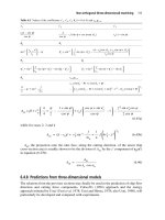
Figure 4.1. The stationary and the rotating reference frame 28
Figure 4.2. Three models of friction 30
Figure 4.3. Block diagram of system to be observer and better controlled 32
Figure 4.4. Comparison of High Gain and Sliding Mode Observers 37
Figure 4.5. Block diagram of a system with a sliding mode observer and
feedforward current compensation 38
Figure 4.6. Comparison of three control strategies (J=1 p.u.) 39
Figure 4.7. Comparison of three control strategies (J=2 p.u.) 41
Figure 4.8. Comparison of three control strategies (J=10 p.u.) 41
Figure 5.1. An inverted pendulum of a disk 45
Figure 5.2. Inverted Pendulum on a disk and its control system. 48
Figure 5.3. Input and Output Membership Functions 50
Figure 5.4. This surface maps the input/output behavior of the controller 50
Figure 5.5. The final shape used to calculate the output and its centroid 52
Figure 5.6. The pendulum and disk response to a 10° disturbance 54
Figure 5.7. The pendulum and disk response to a 25° disturbance 55
Figure 5.8. The pendulum and disk response to a 45° disturbance 56
Figure 6.1. Voltage captures during two quick motor stall current surges 61
Figure 7.1. The ZAP Electricruizer (left) and Lectra Motorbike (right) 64
Figure 8.1. A typical autonomous vehicle system 66
Figure 10.1. The Mexican Hat 71
Figure 10.2. The Shark Fin 72
Figure 10.3. A map of obstacles and line segments 73
Figure 10.4. The potential field created by Mexican Hat Navigation 73
Figure 10.5. The path of least resistance through the potential field 74
Figure 10.6. The resulting path through the course 74
viii
Index of Tables
T
ABLE
3.2. F
EEDBACK PARAMETERS TYPICALLY AVAILABLE FROM MOTOR CONTROLLERS
AND THEIR SOURCES
11
T
ABLE
4.1. T
RANSFORMATIONS BETWEEN DIFFERENT DOMAINS ARE POSSIBLE
28
T
ABLE
5.1.
W
EIGHT
G
IVEN TO
PID C
ONTROLLERS
T
ORQUE
C
OMMAND
49
T
ABLE
5.2.
W
EIGHT
G
IVEN TO
PID C
ONTROLLERS
T
ORQUE
C
OMMAND
51
T
ABLE
6.1. M
OTION
C
ONTROL
C
HIPS AND
P
RICES
59
T
ABLE
6.2. T
OP
10 T
IME
C
ONSUMING
T
ASKS IN THE
D
ESIGN OF
A
UTONOMOUS
E
LECTRIC
V
EHICLES
62