Open-Source Robotics And Proces Control Cookbook Edwards L 242P Newnes Elsevier 2005 Part 7 potx
Bạn đang xem bản rút gọn của tài liệu. Xem và tải ngay bản đầy đủ của tài liệu tại đây (176.06 KB, 20 trang )
108
Chapter 3
sc_calc: andi r18, $07 ; mask off high bit of column#
; Shift left (R1) times to get the desired column latch byte
ldi r17, $01
sc_c_lp: cpi r18, 0
breq sc_c_done
lsl r17
dec r18
rjmp sc_c_lp
sc_c_done:
out PORTA, r17 ; put latch byte on PORTA
nop
nop
out PORTB, r20
nop
nop
andi r20, $C0
out PORTB, r20
; Increment column
column_done: lds r18, currentline
inc r18
andi r18, $0F
sts currentline, r18
; Have we wrapped around to column 0?
cpi r18, $00
brne rfsh_cont
; Yes! Reset pointer and update blink count
ldi r26, low(framedata)
ldi r27, high(framedata)
lds r18, framecounter
inc r18
; See if we’ve had a blink overflow
cpi r18, BLINK_RATE
brne blink_ok
lds r18, flags
ldi r19, (1 << FLAG_BLINK)
eor r18, r19
sts flags, r18
109
Some Example Sensor, Actuator and Control Applications and Circuits (Hard Tasks)
ldi r18, $00
blink_ok:
sts framecounter, r18
rfsh_cont:
; store new frame pointer
sts frameptr_lo, r26
sts frameptr_hi, r27
; Force $80 into timer register to double frame-rate
ldi r18, $80
out TCNT0, r18
out SREG, r0
pop r0
pop r16
pop r17
pop r18
pop r19
pop r20
pop r21
pop r26
pop r27
reti
This is the only project here that includes significant functionality in the main
loop. This loop polls the test-mode bit, and when it is set by the serial ISR, the main
loop calls the test-mode function. Test mode is provided mainly so the user can verify
that all LEDs are wired and functioning correctly. In test mode, each entire column
is illuminated sequentially (0–15), then each entire row is illuminated sequentially
(A–Z). Any miswired or shorted row/column lines will become immediately apparent.
;====================================================================
; Main program loop. Most of the functionality is actually in ISRs.
mainloop:
lds r16, flags
sbrs r16, FLAG_TESTMODE
rjmp ml_nottest
call testmode
call clearscreen
110
Chapter 3
ml_nottest:
rjmp mainloop
;====================================================================
; Test mode
; Destroys R16, R19, R26, R27
testmode:
; PHASE 1
; Walk a line of FFs across the (16) columns
call clearscreen
ldi r18, $10
; Point X at start of framebuffer data
ldi r26, low(framedata)
ldi r27, high(framedata)
ldi r20, $FF
ldi r21, $C0
w_f_0:
lds r16, flags
sbrs r16, FLAG_TESTMODE
ret
lds r16, framecounter
cpi r16, $00
brne w_f_0
; store new data
call clearscreen
st x+, r20
st x+, r20
st x+, r20
st x+, r21
w_f_1:
lds r16, flags
sbrs r16, FLAG_TESTMODE
ret
lds r16, framecounter
cpi r16, BLINK_RATE / 2
brne w_f_1
dec r18
brne w_f_0
111
Some Example Sensor, Actuator and Control Applications and Circuits (Hard Tasks)
; PHASE 2
; Walk a line of FFs down the (26) rows
call clearscreen
ldi r18, 26
; Initialize data
ldi r28, $01
ldi r29, $00
ldi r30, $00
ldi r31, $00
w_r_0:
lds r16, flags
sbrs r16, FLAG_TESTMODE
ret
lds r16, framecounter
cpi r16, $00
brne w_r_0
; store new data
ldi r26, low(framedata)
ldi r27, high(framedata)
ldi r25, $10
s_c_lp: st x+, r28
st x+, r29
st x+, r30
st x+, r31
dec r25
brne s_c_lp
w_r_1:
lds r16, flags
sbrs r16, FLAG_TESTMODE
ret
lds r16, framecounter
cpi r16, BLINK_RATE / 2
brne w_r_1
; shift “on-bit” one left through all 26 bits
cpi r28, $00
breq t_b1
lsl r28
brne t_done
112
Chapter 3
ldi r29, $01
rjmp t_done
t_b1: cpi r29, $00
breq t_b2
lsl r29
brne t_done
ldi r30, $01
rjmp t_done
t_b2: cpi r30, $00
breq t_b3
lsl r30
brne t_done
ldi r31, $40
rjmp t_done
t_b3: lsl r31
t_done:
dec r18
brne w_r_0
rjmp testmode
At the very end of the code, we have a couple of miscellaneous subroutines to
clear video RAM, and to reset all the output latches:
;====================================================================
; SUBROUTINE
; Clear ALL framebuffer RAM
clearscreen:
push r27
push r26
push r18
push r16
ldi r18, $00
ldi r16, (4*16)
ldi r26, low(framedata)
ldi r27, high(framedata)
clslp: st x+, r18
dec r16
113
Some Example Sensor, Actuator and Control Applications and Circuits (Hard Tasks)
brne clslp
pop r16
pop r18
pop r26
pop r27
ret
;====================================================================
; SUBROUTINE
; Sets all output latches to LOW state (ie turn off row/col drivers)
clear_outputs:
push r16
; Set output drivers for ports A,B,C low
ldi r16, $00
out PORTA, r16
out PORTB, r16
out PORTC, r16
; Latch zeros into U2,U3,U4,U5
ldi r16, $0f
out PORTB, r16
nop
ldi r16, $00
out PORTB, r16
pop r16
ret
This page intentionally left blank
The Linux-Based Controller
(A Soft Task)
4
C H A P T E R
115
4.1 A Brief Introduction to Embedding Linux on PC Hardware
Before we start building an “embedded” distribution of Linux for our target platform,
we need to formalize our goals for this system component. The requirements we
define at this point will guide us in selecting our Linux components and determining
how we construct the installation.
■ Almost any embedded application needs to have turnkey characteristics; it
needs to start a specific program at power-on and continue executing until
power-down. Interactive startup events (for example, “press a key to continue”
or “please login now”) should be optional or nonexistent.
■ The time required between power-on and full system functionality should be
minimized.
■ Unnecessary background tasks reduce overall performance, can only have
a negative impact on reliability, and may even introduce other difficulties
such as increased system power consumption or subtle security vulnerabili-
ties. Therefore, any software modules and interface layers not essential to the
actual application should be pruned out.
■ Storage space and RAM are both usually going to be constrained. It is there-
fore desirable to configure installed software for the minimum possible “disk”
and memory usage. (I put quotation marks around “disk” because the non-
volatile boot medium we use may in fact be some nonrotating storage device,
such as flash memory).
116
Chapter 4
■ The major reason for bringing a large, complex operating system into our
project is to facilitate the integration of off-the-shelf peripherals. Therefore,
we need to select our various Linux software component versions for compat-
ibility with the largest range of common consumer-grade hardware.
In this book, we will concentrate on kernel version 2.4.24, which is included
on the CD-ROM for your convenience. This is not the most recent kernel version
available at the time of writing; nor is it the version most commonly associated with
embedded Linux applications. The reason I have selected it is because it is the most
recent stable version in the 2.4.x version stream
18
. The previous major release (2.2.x)
is very widely used in embedded applications today (particularly non-x86 Linux ap-
plications; ARM, MIPS, PowerPC, and so forth), but it is a less-than-ideal choice for
us because the majority of ongoing maintenance work is currently aimed at 2.4.x and
later kernels.
The latest 2.6.x kernels have greatly reduced interrupt latency (vs. 2.4.x) and other
features highly desirable in embedded systems, but there have been some fairly major
structural changes in these kernels. As a result, numerous third-party drivers (e.g.,
LIRC and the drivers for Atmel-based USB WLAN adapters, to take two random but
personally important examples) cannot, at the time of writing, be built for 2.6. In order
to make this text as widely applicable as possible, and to avoid getting bogged down
in descriptions of how to patch various drivers to work with the 2.6 kernel tree, I have
chosen to ignore these newer kernels. You should be aware that 2.6 is the way of the
future; please refer to the companion web site for this book,
where I will post notes and comments on embedding kernel 2.6 in the context of this
text.
In the next few sections of this chapter, I will describe how to build a
bootable
filesystem on a CompactFlash card, ready to start your embedded application auto-
matically at power-on. The exact same steps—perhaps with very minor modifications
such as different target device name—can be used to prepare a variety of bootable
media, incluing ZIP disks, USB “pen disks,” and other miscellaneous removable me-
18
This is constantly changing. As this book was being reviewed, kernel 2.4.26 was released. Although
more than likely everything I’ve written here will “just work” with 2.4.26, I thought it inadvisable
to take the risk of rewriting this text at such a late date.
117
The Linux-Based Controller (A Soft Task)
dia (as long as your target system has BIOS support for booting from these devices).
I’ll also show you how to build a bootable system restore CD-ROM that can be used
to dump an entire system load onto a blank hard disk and make it bootable. If you’re
shipping turnkey Linux systems that must boot off a hard drive, a system restore
CD is virtually mandatory—it is a robust way of ensuring that even in a worst-case
scenario, you won’t have to go out for field service calls or waste money shipping cor-
rupted units to and fro.
It is important to stress that the methods and aims we will describe in this
chapter are not precisely the same as those for building traditional monolithic single-
processor systems running Linux. To take one example in particular, the run-time
library we will be using to interface application code to the Linux kernel is the “full”
version of glibc. Embedded applications would not normally use this very heavy run-
time; they would normally use a cut-down runtime such as uclibc. Deeply embedded
projects would also be considerably more rigorous about eliminating cruft than the
text you’re about to read. The emphasis I’m pushing is ease of assembly and, even
more importantly, good compatibility with “desktop” Linux so you don’t have to
delve too deeply into the mysteries of guru-level embedded Linux magic. If you want
more detail about the subject matter of this chapter, an excellent place to start your
further reading is the Linux from Scratch project at
The companion book to that web site is “Linux from Scratch, Version 4.1,” ISBN
0-9659575-6-X, published by Clearly Open. (That ISBN is for the book with com-
panion CD-ROM—a version without the CD-ROM is also available). Linux from
Scratch covers a lot more territory than I will here, since they are concerned with
providing you with enough information to build distributions with the complexity
level of a complete desktop system.
4.2 Configuring the Development System and
Creating Our Custom Kernel
One very useful side-effect of using a PC as the central system controller is that
you can run all the development tools directly on the target hardware (or possibly
a slightly expanded version of that hardware), eliminating the need for a complex
cross-development system. The main reason I advocate doing this is because bit-
ter experience has taught me that the build and install process for some third-party
118
Chapter 4
Linux drivers has only been tested in the “vanilla” case, that is, building and installing
into the currently active system. Automatic configuration scripts that test for the avail-
ability of specific libraries and/or hardware features (for example, CPU instruction set
extensions such as MMX, SSE, 3DNow! and so on) will also require coercion if you’re
running them on a system other than the target hardware. Debugging these sorts of
issues with cross-compiling and manual installation of these components is a waste of
your time. Thus, I suggest that you start by building your SBC into a fully-configured
PC by adding a keyboard, mouse, hard disk and CD-ROM drive,
19
and perform all your
kernel and utility compilation directly on the SBC. You should install Fedora Core
with a custom configuration; don’t install XFree86
20
or associated frippery (graphical In-
ternet tools, games, GNOME, KDE, etc.) unless you specifically want them. Otherwise,
just install the core operating system, development tools, and kernel development. If
you want an exact list of what to select in the install dialogs, here is a painstakingly
exact description of how to navigate the installation process (note: this information is
correct for Fedora Core 1 “Yarrow.” The reason I am spelling it out in such painstaking
detail is so that you can be certain you’re working with the exact same system configu
-
ration I was working with when I wrote and tested the code in this book):
■ Boot off the CD and type linux text to use the text-mode installer. Vagaries
of the Geode graphics subsystem mean that the graphical installer probably
will not work correctly.
■ Choose “Skip” to skip testing of installation media, and select “OK” in the
welcome dialog.
■ Select “English,” then “us”. Choose the type of mouse, if any, connected to
your system. If you selected a serial mouse, indicate the port to which it is at-
tached (probably /dev/ttyS0).
19
You can actually buy some of the SBCs on our recommended hardware list preassembled in a box
with a power supply, CD-ROM drive and hard disk. However, it’s much cheaper—as much as 50%
cheaper – to put it together yourself. The system fits very elegantly into a housing from an external
5.25″ disk or tape drive, if you happen to have one lying about.
20
If you install XFree86, the system will probably not boot correctly unless you first go into CMOS
setup and ensure that the LCD resolution is set for 1024 × 768 and video memory size is set for
4.0 MB. With certain older BIOS versions, you need to do these steps even if you’re not using the
digital-output LCD port on the board.
119
The Linux-Based Controller (A Soft Task)
■ Accept the default monitor settings, and select “Proceed” in the warning
dialog that follows.
■ If you’re installing on a hard disk that already contains a Linux installation,
Fedora will ask you if you want to upgrade the existing installation, or reinstall.
Select “Reinstall”.
■ Select the “Custom” installation type.
■ Select “Disk Druid” partitioning. The next dialog you see will be Disk Druid.
How you partition your system is up to your own preference, but for this sort
of application I normally create a 256 MB swap partition and use the remain-
der of the disk as the root partition. (No, this is not normally regarded as best
practice; but unless you have special requirements, it’s the simplest partition-
ing scheme for this single-function development system). Always force your
partitions to be primary partitions. After partitioning, you’ll probably get a
dialog warning that swap space is going to be turned on immediately; just
select “OK”.
■ Select “Use GRUB Boot Loader”. In the next four dialogs (all of which are
titled Boot Loader Configuration), you should not need to specify any spe-
cial parameters; just select OK. This will install GRUB in the MBR, with no
special options or password protection.
■ You now need to configure the built-in RTL8139 Ethernet adapter. Since the
configuration we’re setting up now is only used for development, I suggest you
leave it at the default settings, which activate the interface automatically on
boot and attempt to acquire an IP address using DHCP.
■ In the next dialog (Hostname Configuration), you can either leave the set-
tings at defaults, or manually enter a hostname for this system.
■ Since this is a development system that should already be isolated from net-
work attacks, select “No firewall” in the Firewall dialog. Select “Proceed” in
the warning dialog that will follow.
■ In the next dialog (Language Support), just select “OK”.
120
Chapter 4
■ In the Time Zone Selection dialog, select the timezone you’re working in and
select “OK”.
■ Choose a root password and enter it twice in the Root Password dialog.
■ There will now be a LONG pause while the installer analyzes the list of
installable packages. The system isn’t crashed; just be patient. Once the
Package Group Selection dialog comes up, select only the following packages
(deselect all others): “Editors,” “Text-based Internet,” “Windows File Server,”
“Network Servers,” “Development Tools,” “Kernel Development,” and “Sys
-
tem Tools.” Note that in some cases, when you press Space to enable an
option, the system will become unresponsive for up to 30 seconds; this is the
install script analyzing the packages you’ve selected. After you select OK in
the Package Group Selection dialog, select OK in the “Installation to begin”
dialog, select “Continue” in the Required Install Media dialog, and the install
process will commence. At the end of the installation, select “Reboot” and
you’re done.
The process I just described yields a system on which you can build and test your
embedded kernel directly. You can also assemble your bootable CompactFlash image
and write it to a CF card on this same piece of hardware, then test booting off it simply
by altering the CMOS settings on the SBC—which is a big time-saver while you’re
debugging CompactFlash startup issues. However, if you’re unwilling or unable to use
the target SBC as your development system (for instance, if it’s physically installed into
a piece of equipment and it’s difficult to attach development peripherals), there is an
alternative method you can use. This method can be summarized as follows:
■ Take the source for the kernel version you intend to use on the SBC, and
configure and build it for your development system.
■ Install the kernel and modules on your development system, and modify
your bootloader so that it loads this kernel. For the sake of this discussion,
I’ll assume that you named the active, booting kernel image “/boot/bzimage-
2.4.24”. Edit your bootloader’s configuration appropriately.
■ Reboot so that you’re running the same kernel version that you intend to use
on the SBC.
121
The Linux-Based Controller (A Soft Task)
■ Archive the kernel and its configuration. You can back up the important parts
of the active Linux environment simply with the command:
tar cvfz /activekernel.tar.gz /lib/modules/* /boot/bzImage-2.4.24
/etc/modules.conf
■ Clean up the kernel and module directories by executing the commands
make clean in the kernel source directory and rm -rf /lib/mod-
ules/2.4.24 to remove the active kernel modules.
■ Configure the kernel for your SBC, build and install it. If you’re using the Ad-
vantech board or a compatible device, you can use the kernel configuration
I have supplied on the CD-ROM. Don’t use the same path for the kernel
image file (bzImage) as you’re using for the real kernel that boots your
development system, or you might not be able to start the development
system easily if something goes wrong and you have to reboot. I suggest you
install the SBC-specific kernel as /boot/bzImage-sbc. If you’re using the mate-
rials supplied on the CD-ROM, here’s the exact set of commands you’ll need
to execute:
cd /usr/src
tar zxvf /mnt/cdrom/linux/linux-2.4.24.tar.gz
cd linux-2.4.24
cp /mnt/cdrom/linux/geode-config .config
make dep ; make bzImage ; make modules ; make modules_install
cp arch/i386/boot/bzImage /boot/bzImage-sbc
■ Configure, build and install any additional drivers you need (for example,
LIRC, mentioned later in this text, drivers for WLAN devices, and so on).
■ Archive the SBC’s kernel configuration:
tar cvfz /sbckernel.tar.gz /lib/modules/* /boot/bzImage-sbc /
etc/modules.conf
■ Immediately after you finish archiving up the completed kernel installation
for the SBC, restore your development system’s bootable kernel set with the
following commands:
122
Chapter 4
rm -rf /lib/modules/2.4.24
cd /
tar zxvf activekernel.tar.gz
This way of doing things is not quite as desirable as development on the real
hardware, because you still have to hand-tweak configuration files for applications
and libraries that auto-configure for installed hardware. You may also have some
(usually very minor) problems with module dependencies, requiring manual editing
of the modules.dep file, and you obviously can’t actually test the kernel and drivers
on your alien development hardware. However, this system does allow you to build
the kernel and all the installable kernel modules in a reasonably robust and simple
way. Note, by the way, that many installable driver packages place daemons, libraries,
utilities and other files in various directories other than /lib/modules/kernelversion,
and some of these packages modify startup scripts to load daemons automatically on
boot. You’ll have to identify and copy these extra files and script modifications across
to the SBC by hand.
The reason I advocate this somewhat tortuous process in lieu of performing a true
“cross-build” (coercing install scripts to use a kernel build tree different from the active
one reported by uname(1)) is because I have frequently encountered bugs in the scripts
and makefiles for various third-party kernel drivers and other software, which only
manifest if you are installing to a destination other than the current (booted) kernel
directory. It would appear that most such drivers are developed and tested under the
assumption that you will be building and installing the driver into the currently active
environment. Rather than analyzing and testing the configure scripts and makefiles
for each third-party driver on a case-by-case basis (and perhaps risking that a critical
component won’t be transferred correctly to your target system), it is much simpler
simply to build “live.” If you can’t or won’t build on a truly live installation on the
real target hardware, the next best thing is to simulate, on your development PC, the
same kernel environment that will be running on the SBC.
All of this complexity is avoided if you build your Linux environment directly on
the target platform, so I reiterate: if at all possible, build up your SBC into a semi-
complete, usable system so you can build your software directly on the real hardware.
It will save you a vast amount of time and frustration.
123
The Linux-Based Controller (A Soft Task)
4.3 The Linux Boot Process—Creating a Bootable CompactFlash Card
Let’s begin this section where your embedded application begins: with the power-
on boot process of the SBC and Linux. At power-on or hard reset, the BIOS probes
attached hardware and builds a list of bootable devices. It refers to a boot priority
table in ROM or nonvolatile CMOS RAM and scans available boot devices in the
order specified in that priority table. For each device, the first sector on the disk is
read into RAM and scanned for a boot signature. If the signature is found, the BIOS
assumes the disk is bootable, and jumps into the bootsector code copy in RAM. This
code, installed by the operating system’s partitioning or formatting utility, loads the
remainder of the operating system, possibly in several stages. In a Linux system, this
tiny snippet of bootstrap code is either a header prepended to the kernel itself (such
a configuration has just enough intelligence to load the remainder of the kernel
from consecutive sectors and jump into it), or the first stage of a bootloader program
that can gather configuration information from various sources and handle a more
complicated load process. In the case of a Linux installation, the bootloader loads
at least the kernel image, and perhaps also an initial RAMdisk (initrd) image into
memory before passing control to the kernel. The initial RAMdisk image is intended
to contain modules, scripts and other data that may be required by the kernel be-
fore the real root filesystem can be mounted. It is normal for the on-disk copy of the
image to be compressed with gzip(1). Once the initrd image is loaded into RAM,
decompressed and mounted, the kernel spawns /sbin/init, which continues the boot
process
21
.
There are a myriad different possible ways to organize the boot process of a
Linux system. When booting from a hard disk, it is usual to employ either LILO
(LInux LOader) or grub—modern Linux distributions tend to favor grub. Both of
these programs are powerful boot-manager applications capable of loading different,
user-selected operating systems at boot time, offering simple password protection,
operating system selection menus on the local console or a serial port, and numerous
21
Please note that this is a considerable simplification. There is actually a handover point where the
initial RAMdisk is destroyed and the real root filesystem is mounted, and there are several other
possible steps and forks in the boot process. We won’t be dealing with all these options in our ap-
plication, because we will be running permanently out of the initial RAMdisk.
124
Chapter 4
other features. They’re not routinely necessary for an embedded application, though
it is possible to use them on media other than hard disks if you want to. One ap-
plication where this sort of boot menu can be handy is if you want to provide some
kind of emergency recovery facility where the user can boot the system in emergency
mode and perform some sort of recovery or diagnostic operations. However, what we
are trying to do (make a bootable CompactFlash card or CD-ROM) is more akin to
preparing a bootable Linux floppy disk than a full-blown hard disk boot. In fact, in
the case of the bootable CD-ROM, it’s almost exactly like a floppy disk.
The ancient and still somewhat documented method of preparing a bootable
Linux kernel floppy is to patch (some might say, “mercilessly hack”) the kernel im
-
age using the ancient and deprecated rdev(8) utility, then use the dd(1) utility to
write the kernel image itself (bzImage) directly to a floppy disk, possibly followed by
an initial RAMdisk image. If you’re searching the Internet for information on how
to build bootable floppy disks, this method is likely to crop up high in your search
results, but it’s a red herring. There are a few problems with it, and the main prob
-
lem is this: After the kernel code starts executing, BIOS functionality is more or less
completely preempted. This means that if you want the kernel to be able to load an
initial RAMdisk, it either has to be on an actual, separate floppy disk, or it has to
be small enough to fit right after the kernel image on the first floppy disk. As kernel
sizes have increased, it has become close to impossible to fit everything needed in
a kernel (typically as much as 700K) and initial root filesystem onto a single floppy
disk. Thus, it’s unreasonably difficult to make, say, a bootable CD-ROM using this
method, because as soon as the kernel starts executing and goes looking for its initial
RAMdisk image (on a second floppy disk), it will try to load it off actual floppy sec
-
tors instead of going through the BIOS’s emulated floppy-on-CD-ROM layer, and the
boot process will fail.
Another way of constructing a bootable medium is to format your device, or a
portion of it, as FAT, make it bootable with your choice of DOS versions, and cre-
ate an AUTOEXEC.BAT that uses the LOADLIN utility to load a kernel and initial
RAMdisk. LOADLIN was popular for making “Start Linux now!” icons on systems
running Windows 3.x through 98, because it allows you to start Linux directly from
a DOS-based operating system without needing to reboot. It also allows you to do
tricky things like having Linux on a secondary drive (perhaps a removable drive)
125
The Linux-Based Controller (A Soft Task)
with no footprint at all on your main Windows drive—and furthermore, you don’t
need to worry about Windows or a bootsector virus accidentally wiping out your
LILO or grub installation. As long as you can boot Windows, you can boot Linux.
The downside to the DOS + LOADLIN method of doing things, from our perspec-
tive, is that it requires a whole throwaway operating system kernel just to act as a
bootloader. This is an unnecessary waste of flash space, and it also violates the uni-
versal common sense design rule of eliminating software layers not actually necessary
for the application at hand.
As a result, we’re going to use the SYSLINUX bootloader in our system. SYS-
LINUX is a beautifully small and simple piece of software. It consists of an installer
utility (syslinux under Linux, SYSLINUX.EXE under DOS/Windows), a small loader
module, and a kernel and initial RAMdisk image that you supply. The function of
the syslinux utility is basically the same as the “/s” switch to the DOS FORMAT
command; it makes the target media bootable. Instead of installing the MS-DOS
IO.SYS, MSDOS.SYS and COMMAND.COM files, however, syslinux copies across
its own loader module, which is called LDLINUX.SYS. The loader module examines
and executes the configuration file SYSLINUX.CFG, which is a plain text file (in
the root directory of the boot medium) instructing SYSLINUX which kernel to load,
what options to pass it, and what initial RAMdisk to load.
Once the kernel and initial RAMdisk are loaded, a “normal” Linux distribution
will mount the real root filesystem (usually a hard disk—sometimes an NFS share-
point or some other sort of device) and discard the contents of the initial RAMdisk.
In our embedded application, however, we’re going to run with a RAM-based root
filesystem. This minimizes wear on the flash media, and also improves system reliabil-
ity (since we’re never writing any changes to the on-disk copy of our root filesystem,
it is always a known-good start point). Whether running the root filesystem out of
RAM or from some other device, the next thing the kernel does is to run /sbin/init
to process system startup scripts and bring up whatever network connections, device
drivers and daemons you wish to have running on the system.
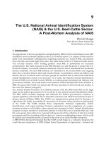
Figure 4-1 summarizes just a few of the possible paths we could travese to start up
our Linux system, including the methods described above. We are going to follow the
path that goes from BIOS to SYSLINUX to kernel, and then directly to /sbin/init.
126
Chapter 4
Figure 4-1: Some possible Linux boot paths
By the way, this is an appropriate moment to point out why it’s extremely desir-
able to use FAT format on your bootable CompactFlash card. The most obvious
reason is that Windows can read and write it directly. This makes field-upgrades of
firmware much easier than they would be if you were using a Linux-specific filesys
-
tem. Instead of having to write, or at least deploy, a disk-imaging utility to your users,
you can simply email them new kernel and initrd files, and tell them to use a regular
USB CompactFlash reader to copy the new files onto their existing card. Another
related benefit is that any logged data your embedded appliance cares to write to the
card will be accessible directly by Windows users, without requiring any special drivers.
A more subtle reason for using FAT is that, by and large, removable flash media
are designed with the assumption that FAT will be the filesystem in use. The exact
implications of this are rather “gray” (i.e., implementation- and situation-specific),
but for example, many NAND flash devices—primarily SmartMedia, but also some
CompactFlash cards—have a low-level format specification that specifies a 1:1 cor-
BIOS
DOS
GRUB or
LILO
SYSLINUX
LO
ADLIN
Kernel
Initial RAMdisk mounted
“Real” root f
ilesystem mounted
/sbin/init begins processing star
tup scripts
127
The Linux-Based Controller (A Soft Task)
respondence between FAT clusters and erasable flash blocks. Using the correct FAT
format for your particular card size results in far fewer erase-write cycles, thereby
extending the operational life of the card.
Note: If you are using extremely small CompactFlash media (less than 16 MB
in size), you may encounter problems using mkfs (or, more strictly speaking, mkfs.
msdos) to format the card; you will receive an error that the volume is too small to
create a filesystem. I have not found a fully satisfactory workaround for this problem.
The easiest way to avoid the problem is to use some other appliance or operating
system—Windows or a digital camera, for instance—to format the card. You can also
use the mformat(1) command, from the mtools package, to format the card properly.
Now that I’ve outlined to you the combination of software we intend to use, let’s
actually install it on the card. I’ll assume you are doing this on an actual PCM-5820 or
similar SBC, where the CompactFlash slot is wired in true-IDE mode, configured as the
master device and connected to the secondary IDE interface; i.e., at /dev/hdc
22
. I’ll also
assume that the card is already partitioned and formatted as FAT12, FAT16 or FAT32
(this will be true of a brand-new card out of the box). The sequence of steps to follow is:
1. Install SYSLINUX on the card:
syslinux /dev/hdc1.
2. Mount the card so we can access it: mount /dev/hdc1 /mnt.
3. Copy the Linux kernel across:
cp /boot/bzImage-sbc /mnt/LINUX.
4. Create a text configuration file called SYSLINUX.CFG in the root of the
card (/mnt/SYSLINUX.CFG). A suggested configuration file might be simply:
DEFAULT LINUX initrd=INITRD.IMG root=/dev/ram
You can also add other kernel parameters to this file—for instance, you could
redirect the console to a serial port (console=/dev/ttyS0), specify a different
video startup mode (vga=mode-number), and so on.
5. Unmount the card: umount /mnt.
6. The card is now bootable (though not usefully so—read on!).
22
Keep in mind that true-IDE mode does not support hot-swapping. You must power off the system
before inserting or removing CompactFlash cards.