Carbon Materials for Advanced Technologies Part 6 pot
Bạn đang xem bản rút gọn của tài liệu. Xem và tải ngay bản đầy đủ của tài liệu tại đây (639.99 KB, 35 trang )
155
increasing
X
or
Y
fiber loading. However, when the electrical resistivity was
plotted as a function
of
the total fiber volume fraction, a linear relationship was
found. This demonstrates that impedance exists due to the high electrical
resistivity in the fiber transverse direction, and also explains why the electrical
resistivity is higher in the
Y
direction.
Table
8.
Room temperature density
(p,
glcm')
thermal
conductivity
(K,
W1m.K)
and
elechical resistivity
(0,
microhm-cm)
of
various
VGCF
reinforced
aluminum
matrix
composites.
ID
P
V,
(total
I
X
I
Y),
%
K
(X
I
Y),
WImK
0
(X
I
Y)
1
2.58 17.2
I
17.2
IO
397 I225 6.21 17.70
2 2.55 20.6
I
12.4
I
8.2
339 I287
3
2.56 19.3
I
15.4 13.9 356 I265
TO
2.51 26.61 13.3 113.3 333
l-
T1 2.50 27.9
I
27.9
IO
534
I
-
T2 2.44 36.5 136.5
IO
642
I
-
T3 2.53 22.1 122.1
IO
406
I
-
VGCF
2.0
-
1950
parallel
to
fiber axis
-20"
perpendicular
to
fiber axis
7.23 18.93
6.27
I
8.16
8.32
I
-
60
parallel
to
fiber axis
>loo
perpendicular
to
fiber axis
A1
2.7
-
200
-4
a.
Estimated
value.
Although VGCFIA1 composite exhibits excellent thermal conductivity, the
mechanical properties are moderate. The average flexural strength and modulus
of
a
35%,
by volume, VGCFIA1 composite is about
150
MPa
(22
ksi) and
1.50
GPa
(0.22
msi), respectively. While the composites indicate relatively modest
mechanical property values compared to composites reinforced with, for
example, PAN fiber, they are sufficiently robust to allow their use in most
applications where aluminum is satisfactory, such as in most electronic
packaging applications. In addition, the CTE of aluminum, about
22
to
25
ppd, can be dramatically reduced to less than 10 ppmK by the addition of
VGCF. These
data
demonstrate the prospect of carbon fiber composites having
several times the thermal conductivity
of
aluminum, yet retaining lower
mass
and coefficient of thermal expansion, promising to substantially improve
composite performance while providing important weight savings.
4.1.4.
Summary on VGCF composites
The above data represent the first from composites fabricated with fixed catalyst
VGCF. A review of the data leads to the conclusion that the thermal and
electrical properties of this type of carbon fiber are perhaps the most likely to be
exploited in the short term. While mechanical properties
of
the composites are
not as attractive as the thermal and electrical, it may be noted that
no
effort has
156
yet been made to develop a fiber-matrix interphase in any of the composites.
Also, the mechanical properties may be limited by the frequency of defects
manifested in surface crenulations demonstrated
on
the heat-treated and highly
graphitic fixed-catalyst VGCF, as well as a relative lack
of
cross-lmking
between graphene planes. Finally, the mechanical strength and modulus, while
not high enough to compete with other carbon fiber composites for structural
applications, are still sufficiently high to allow components to be fabricated for
thermal and electrical applications.
4.2.
Composites
based
on floating
catalyst
fibers
The premise that discontinuous short fibers such as floating catalyst VGCF can
provide structural reinforcements can be supported by theoretical models
developed for the structural properties of paper Cox
[36].
This work was
recently extended by Baxter to include general fiber architecture
[37].
This
work predicts that modulus of a composite,
E,,
can be determined from the fiber
and matrix moduli,
E,
and
E,
respectively, and the fiber volume fraction, V, by
a variation of the rule of mixtures,
I
E,
=
EmVm
+
EfVf
g(d)f(Q)
where the functions, f and
g,
take on values between
0
and 1. The function g is
small for particles having a low aspect ratio, but increases rapidly as the aspect
ratio increases. The function f is dependent upon the orientation of the fibers,
8,
and is greatest for uniaxial alignment.
Baxter's fiidmgs imply that if floating
catalyst fibers
-
which have a very high aspect ratio
-
can be restricted in
orientation to
two
dimensions, the resulting composite could be several times as
stiff as glass-reinforced composites.
It is only recently that limited efforts have been directed towards composite
synthesis using the sub-micron floating catalyst form of VGCF.
In
one
experimental effort, Dasch
et
al.
[38]
reported the fabrication of thermoplastic
composites reinforced with randomly oriented VGCF, up to
30%
of volume
fraction, having diameters of
0.08
mm
and lengths of
2.5
mm.
All the
composites exhibit similar flexural strength near
70
MPa
(10.2
ksi), in accord
with Baxter's theory for
3D
short fiber reinforced composites.
Also, flexure
modulus increased with fiber volume fraction in accord with calculations based
on Cox's theory for random
3D
short fiber reinforcements. While these data are
relatively inauspicious, the theoretical treatments do indicate that useful
reinforcement is obtained through partial
2D
reinforcement and controlled
fibedmatrix interface. In the above study, no attempt to optimize the
fiberlmatrix interface was reported.
157
Due
to
the success in producing sufficient quantity of floating catalyst VGCF,
we recently investigated the tensile properties
of
polyphenyene sulfide
(PPS)
matrix composite. The tensile properties were evaluated according to the
ASTM
D638
(Type
D)
Standard.
For
comparison, the mechanical properties
of
neat
PPS,
and
40%
(by weight) glass
fiber reinforced PPS are also included. It is apparent that the tensile modulus
has been greatly enhanced and VGCF is shown to be a better reinforcement than
glass fiber in this respect. On the other hand, composite strength is lower than
that of neat matrix
PPS.
This
is
again attributed to the lack of fiber surface
treatment to obtain desired fiber/matrix interface.
The data are given in Table
9.
Table
9.
Tensile properties
of
PPS composites. All the fiber fractions are in weight
percents. Data on Specimens a and
b
are taken from Modem Plastic Encyclopedia
’96,
Mid-Nov
1995
Issue.
ID
Fiber
V,
%
Modulus, GPa Strength, MPa
P-3
VGCF
<30 12.5k0.83 28.229.7
BM
VGCF
<30 7.64+0.0.28 48.25 1 5.2
a
Glass
40
1.1
to
2.1
b
none none
3.3
65.5
to
86.1
VGCF reinforced concrete has also been studied
[39].
VGCF in concrete serves
to increase the flexural strength, flexural toughness, and freeze-thaw durability,
and to decrease the drying shrinkage and electrical resistivity. At a fiber volume
fraction of
4.24%,
a flexural strength as high as
12.22
ma, compared to
1.53
MPa for neat concrete, and a flexural toughness as high
as
12.305
MPa-mm’l2,
compared to
0.038
MPa-mm”2 for neat concrete, were reported. In a similar
application, a small amount of the fiber
(0.35%
by volume) was added to mortar
to
increase the bonding strength to old mortar. The resultant increase in shear
bond strength was
up
to
89%.
Another application utilizing the excellent electrical conductivity of VGCF is
reinforced concrete for smart structures
[42,43].
The volume electrical
resistivity of such a smart structure increases upon flaw generation or
propagation. Thus non-destructive detection of flaws in the concrete
may
be
possible. The change in electrical resistivity can also be correlated to elastic and
inelastic deformation, and fracture of the material, offering the potential of non-
destructive damage assessment. Other properties, such as thermal and electrical
conductivity, of composites based on floating catalyst VGCF have been
investigated. Dasch
et
al.
[38]
studied the thermal conductivity of thermoplastic
composites and found that although the thermal conductivity increased with
fiber volume fkaction, the values were much lower than expected. It is thought
that the low thermal conductivity is because threshold values of fiber loading
needed for percolation theory were not achieved in these composites
[40].
158
The excellent electrical conductivity of VGCF composites makes them ideal for
application in, for example, advanced electroconductive adhesive agents
[41].
A
number of carbon reinforcement, includmg VGCF, PAN-based carbon fiber,
pitch-based carbon fiber, natural graphite power, and electroconductive carbon
black were evaluated for use in epoxy-based adhesive. The room temperature
electrical resistivity of VGCF reinforced epoxy was found to be 0.27 Q-cm,
which could not be achieved using the other carbon fillers investigated. The
adhesive strength was found to be higher
than
that of neat epoxy.
5
Potential Applications
5.1.
Thermal management
A
significant portion of the development work conducted on VGCF composites
has been motivated by the potential of these composites for high performance
thermal management applications, such as electronic heat
sinks,
plasma facing
materials, and radiator fins.
Both
the fiied catalyst and the floating catalyst
VGCF have the potential to be economically important for thermal management
or high temperature composites.
Composites fabricated with fiied catalyst VGCF can be designed with fibers
oriented
in
preferred directions to produce desired combinations of thermal
conductivity and coefficient
of
thermal expansion. While such composites are
not likely to be cost-competitive with metals in the near future, the ability to
design for thermal conductivity in preferred directions, combined with lower
density and lower coefficient of thermal expansion, could warrant the use of
such VGCF composites in less price sensitive applications, such as electronics
for aerospace vehicles.
Composites fabricated with
the
smaller floating catalyst fiber are most likely to
be used for applications where near-isotropic orientation is favored. Such
isotropic properties would be acceptable in carbodcarbon composites for
pistons, brake pads, and heat sink applications, and the low cost
of
fiber
synthesis could permit these price-sensitive applications to be developed
economically.
A
random orientation
of
fibers will give a balance of thermal
properties in all axes, which can be important in brake and electronic heat
sink
applications.
5.2.
Mechanical properties
A
major stimulus for the development
of
any low-cost carbon fibers is for their
potential applications
in
the automotive industry, which identifies carbon fiber
159
reinforced composites as being necessary to meet Federal fuel efficiency
standards. The projected production costs of floating-catalysts VGCF are with
the range needed to be considered as a candidate reinforcement for automotive
composite components. The performance of such carbon fiber reinforced
composites
is
at this time still open to conjecture.
A
very high degree of graphitic perfection in the fibers, and by inference, a high
modulus of elasticity has been determined by x-ray diffraction for selected
preparations of floating catalyst VGCF even without subjecting the fiber to any
post-growth heat treatment. Though the small diameter of the fibers precludes
direct measurement of modulus, this attribute has been substantiated by early
investigations of the fiber as a reinforcement in rubber. Based on the presumed
high modulus, and as suggested by theory described earlier, VGCF could be
used to produce thermoplastic- and thermoset-matrix composites with elastic
moduli comparable or exceeding that of aluminum, provided that preferential
orientation in
two
dimensions can be obtained,
Because it
is
a.
small discontinuous reinforcement, floating catalyst VGCF may
be pelletized and incorporated into commercially available thermoplastics,
thermosets and elastomers and perhaps may be used directly
in
existing high
volume molding processes without any significant new manufacturing
development. Because of the inferred extraordinary intrinsic properties of the
floating-catalyst VGCF, particularly elastic modulus, it is expected to enable a
reduction in the amount of material required to produce a given stiffness, thus
providing net weight and cost savings. Furthermore, it is produced in a process
somewhat analogous to that of carbon black, that is, by direct conversion from
a
simple hydrocarbon source. Process economics are thus more favorable for
VGCF and a cost
of
less than $3Ab could be more easily attained than for PAN
or pitch-based carbon fibers.
Accordingly, it is perceived that floating-catalyst VGCF may have a significant
future as
a
reinforcement for in automotive components, where they could offer
advantages
of
weight reduction, improved performance, parts consolidation and
elimination, and reduction of assembly steps. While discontinuous VGCF is not
expected
to
compete with continuous carbon fiber composites where demanding
loads require premium values of mechanical properties, VGCF composites
could be used for'the manufacture of composite components which are currently
reinforced by chopped glass fiber. Such components include sheet molding
compounds for automotive body panels, and under-hood components such as
fans, rahator parts, air conditioners, air filters, inlet manifolds, brake fluid
reservoirs, air control valves, heater housings, windshield wiper reservoirs and
gears.
5.3.
Electrical conductivity
There are applications for engineered plastics where glass fibers are not suitable
because they are electrically insulating andor are too large. These include
panels for electromagnetic interference shieldmg, electrical boxes and
connectors, and antistatic composite components. The growth in the electronics
industry, and the use of plastic housings withm this market, has generated a
need for conductive materials to attenuate ambient
EM
originating from within
and without the housing. While metal coatings, fibers and screens are suitable
for ths purpose, carbon fiber has been found to provide a Lightweight solution
for this type of plastic application, and are particularly well-suited for hand-held
electronics.
Another application for VGCF is as an electrode material for lithium-ion
batteries. These power storage devices require an anode that is conducting, has
high effective surface area, and the ability to be easily and reversibly
intercalated with the Li ions. VGCF is a candidate material because it can be
produced with a small diameter and consequent hgh surface-to-volume ratio. It
adltionally posses a hghly graphic structure.
6
Manufacturing
Issues
6.
I.
Fixed
catalyst VGCF
6.1.1.
Cost
As noted previously, cost of carbon fiber is a primary barrier to its more
extensive use
in
commercial markets. The cost of production of the fixed
catalyst VGCF will always be high relative to floating catalyst fiber. However,
this type of VGCF has shown considerable potential in carbodcarbon
composites for high performance applications, and may be applicable in those
high performance areas that are less cost sensitive. The current cost of
production, approximately
$1,000
per pound, could be reduced by an order
of
magnitude through higher efficiency and production rates. Such a reduction
in
production cost could dramatically increase its applicability even for the niche
markets where it is most Likely to have a future.
6.1.2.
Production rate
The production of fixed catalyst VGCF has typically been performed using
batch processing The rate limiting step is the deposition of pyrolytic carbon
on
the walls of the fiber, thus thickening it. Analogy to semiconductor processing
teaches that higher efficiency could be accomplished through conversion to a
161
semi-continuous process, ehinating the time required to cycle the furnace from
room temperature to process temperature.
6.1.3. Understanding/control of defects
As
noted, a large variation in the morphology of VGCF is possible, ranging
from ribbons, helices (Motojima
et
al.
[44]) and fiber which grows in random
directions, to relatively long unidirectional cylindrical fibers having uniform
diameters and surfaces. Much of the variation in fiber morphology results from
the choice
of
catalyst, coupled with the concentrations of hydrocarbons and
hydrogen and the temperature in the fiber growth reactor. See for example
recent publications by Herreyre and Gadelle [45], and Nolan
et al.
11461. One
common feature of VGCF which has been thickened to diameters typical of
other carbon fibers is the appearance of crenulations along the length of the
fiber. The perfect graphite fiber would be one which is devoid of defects and
crystallographic imperfections, producing a straight fiber which
is
free of
crenulations would be beneficial. One area of research at AS1 has been the
lengthening and thickening of the fibers under conhtions which can be
independently varied in order to illuminate the mechanisms leading to the
formation of crenulations
[47].
However, the early results of this study have
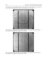
generated more questions than answers, as shown in Fig.
9,
which is a scanning
electron micrograph showing the fiber produced when hckening at
temperatures higher than normal process temperatures. The presence of
crenulated fiber, as well as distinctively beaded fiber is observed. The etiology
of this phenomenon
is
as yet unknown, emphasizing the that additional study of
fiber growth mechanisms is warranted for further control and improvement of
fiber properties.
6.2.
Floating
catalyst
VGCF
6.2.1. Process scale-up
To exploit the numerous applications for floating catalyst VGCF in engineered
plastics, production rates are projected to be on the order of several pounds per
hour from a single tube reactor. Demonstration experiments on a small scale
have shown feasibility of accomplishing the desired rate of production.
Economic production of such quantities will involve recapture of energy in the
heated unreacted gas which exits the reactor, as well
as
automated collection,
debulking, and preform fabrication systems.
6.2.2. De-buhg
In order for VGCF to be successfully incorporated into engineering composites,
it must be available in forms which composite fabricators are equipped
to
handle. Since VGCF is bulky and discontinuous as produced, it is not amenable
to the textile processing used for continuous carbon and glass fiber.
Thus
fiber
162
preforms are required which will enable the post-production debulking of the
fiber for shipment, and straightforward utilization in conventional composite
synthesis operations. Such preforms include pellets, paper, felt, and perhaps
woven yarns; the desired preform of the material is expected to be different for
different industries. Pelletization and paper fabrication are methods currently
under development at ASI.
Fig.
distinctively
beaded
fiber
as
Paper is produced by incorporating fiber into a slurry, and then filtering through
a mesh to leave a random,
two
dimensionally-oriented array of short fibers.
Typically a thermoplastic or thermosetting binder which is compatible with the
desired matrix is added for papers made of carbon fiber
[48].
To
achieve
appropriate properties of carbon fiber paper, it may be necessary to optimize the
length and aspect ratio of the VGCF, or to
mix
it with other fibers having
desired fiber properties. Paper fabricated with VGCF could enable
two-
dimensional orientation
of
the fiber, shipment and use of the fiber from rolls,
and machine handling to incorporate into desired composite components.
Pelletization can be achieved by using high shear mixing to blend and disperse
the
VGCF
into a slurry which may contain a surfactant and sizing, followed by
drying and grinding into chips or pellets
[49].
Also ball milling has been used
to reduce the aspect ratio, which also serves to reduce the degree of birdnesting
and partially de-bulk the fiber.
163
6.2.3.
Sizinghterphase development
A fundamental aspect of any composite system is the establishment of an
appropriate interface between fiber and matrix. The mechanical prope&es of
the composite are strongly governed by the degree of adhesion between the fiber
and matrix, although the optimum properties are not necessarily achieved with
the highest possible degree
of
adhesion. However,
in
order to effectively
transfer load to and between fibers, a significant degree
of
coupling must exist.
Appropriate interfaces between reinforcement and the desired matrix have been
developed for all successful composite systems, including glass fiber and
continuous carbon fiber.
Optimization of the interface has not been achieved for any of the VGCF
composite systems of choice.
In
the case of continuous carbon fiber, means of
oxidizing the fiber were first developed using batch laboratory processes. These
were followed by the development of electrochemical baths to oxidize the
continuous fiber for economic application in industrial production volumes. For
the discontinuous form in which VGCF currently is produced, such interface
optimization to create active sites
on
the fiber surface and thus promote
chemical and physical bonding with selected matrix materials,
is
expected to
include in situ surface treatments as the fiber is produced, and would be
followed by application of coupling agents or sizing to add functional groups,
and
to
assist
in
debulking and handling.
6.2.4.
Alignment
A number
of
composite applications exist where isotropic orientation of the
fiber
is
either preferred for isotropy of composite properties, or is tolerated as
long as minimum thresholds for requisite properties are achieved.
An
example
of the former would be carbodcarbon pistons, where a low isotropic coefficient
of thermal expansion would be desirable. The latter type application includes
polymer matrix composites for
EM1
shielding or for antistatic applications.
As
demonstrated by the theoretical modeling discussed earlier, preferred orientation
of the fiber will be necessary to optimize mechanical properties in composites.
Some degree of alignment may be possible for composites synthesized by
injection or other molding processes, and by use of VGCF paper preforms
in
which the fiber
is
preferentially oriented into two dimensions.
Methods
of
forming yarns may also be possible, thus enabling VGCF use through
conventional textile processing means.
6.2.5.
Environmental and safety issues
Airborne particles with diameters less than
1
micron, as in the case of asbestos,
are potentially respirable; therefore, the manufacture of all submicron diameter
carbon particles includes a responsibility to ensure that no health hazards are
164
present in the production or use of such VGCF.
Additionally, various
hydrocarbons can be formed during VGCF production which are of concern for
health reasons, analogous to the manufacture of carbon black.
It is envisioned that the first issue, particle size within a respirable range, will be
dealt with by continuous containment of the floating catalyst fiber from the
point of its formation through to permanent entrainment in the matrix material
of choice. As currently produced, this type of fiber is entangled, or birdnested,
and resembles cotton (except for the color). The degree of entanglement is
so
complete that periodic air sampling of the exhaust from the reactor has revealed
no evidence of dispersed individual fibers. The fiber tends to be contained into
birdnested balls by the current production method. Higher volume production
rates may impact
this
condition; however, higher production rates will also
require collection systems such as water spray as the fiber exits the reactor,
followed by application of sizing, pelletization, paper formation, or other
debulking process, similarly leaving the fiber in a state of agglomeration and
containment. The process will be completed by entrainment of the fiber
in
a
polymer or other matrix material when the composite is fabricated. Thus
exposure to indwidual fibers is anticipated to be an extremely rare exception to
anticipated normal handling operations.
With respect to the formation
of
unwanted polyaromatic hydrocarbons in the
pyrolytic process, it has been shown that conditions can be maintained where
such formation is negligible according
to
EPA and
OSHA
standards.
As
production rates are increased, it will be incumbent on any manufacturer to
maintain a set of operating parameters which produce an environmentally-
benign product; however, current information regarding the process for fiber
formation reveals no barriers to accomplishing this.
7
Conclusions
As
observed by Philip Walker, Jr.
[50],
carbon is an old and yet a new material.
Numerous investigations into the mechanisms of vapor grown carbon fiber
formation, and the properties of the various types of fibers, have established this
material as a unique and intriguing component of the set of forms that may be
synthesized from carbon. From these studies, methods of economic production
of VGCF have been developed wluch promise low cost, high modulus graphitic
fiber as a new commodity for broad use in commercial applications for
engineered plastics. Work on composites of
VGCF
is essentially still in its
infancy, yet composites have been fabricated which have established highest
values for properties of thermal and electrical conductivity among similar
composites. Future work in the areas of interphase and preform development
165
are expected to enable the use of VGCF
in
several automotive and electronics
industry
applications, stimulating
the
creation
of
a manufacturing base for
VGCF
and
VGCF composites synthesis.
The versatility of
VGCF
as an
engineering material portends a broad scope of applicability, with prospects of
founding a
new
industry
for the
21"
century.
8
References
1.
2.
3.
4.
5.
6.
7.
8.
9.
10.
1
I.
12.
13.
14.
15.
16.
17.
IS.
19.
20.
-1
Oberlin, Endo, M and Koyama, T., Filamentous growth of carbon through benzeine
decomposition,
J.
of Ciystal Growth,
1976, 32,335
.
Baker, R.T.K., Catalytic growth
of
carbon filaments,
Carbon
,
1989,27(3) 315 323.
Tibbetts, G.G., Why are carbon filaments tubular?,
J:
Crystal Growth,
1984,
66,
632
Rodriquez,, N.M., A review of catalyhcally grown carbon nonofibers
J.
Mater. Res.,
1993, 8(12), 3233.
Dresselhaus, M.S., Dresselhaus, G., Sugihara,
K.,
Spain, I.L
Goldberg,, H.A
Graphite fibers and filaments, Springer-Verlag, New York,
1988.
Bartholomew, C.H., Carbon deposition in steam reforming and methanation, Catal
Rev. Sci. Eng.,
1982, v24,67 112.
Baker, R.T.K, Chemistry and physics of carbon, Marcel Dekker, New York,
14, 1978,
Trimm, D.L., The formation and removal of coke from nickel catalyst, Catal . Rev. Sci.
Eng.,
1977, 16, 155 189.
Koyama,
T.,
Endo
M.
and Onuma,
Y.,
Carbon fibers obtained by thermal
decomposition
of
vaporized hydrocarbon, Japan
J.
Appl.
Phys.,1972,1
I,
445.
Koyama, T., Formation
of
carbon fibers
from
benzene,
Carbon,
1972,
IO,
757 758.
Endo, M. Shikata,
M.,
Momose, T. and Shiraishi, M.
???,in
Ext. Abstr.
17"
Biennial
Conf Carbon,
1985,
p,
295
Tibbetts, G.G., Vapor-grown carbon fibers: status and prospects,
Carbon,
1989, 27(5),
745 747.
Tibbetts, G.G., Gorkiewicz, D.W., and Alig, R.A.
A
new reactor for growing carbon
fibers from liquid- and vapor-phase hydrocarbons,
Carbon,
1993,3 1(5), 809
814.
Tibbetts, G.G., Bernardo, C.A., Gorkiewicz, D.W. and Alig R.L. Role of sulfur in the
production of carbon fibers
in
the vapor phase,
Carbon,
1994,32(4), 569 576.
Tibbetts, G.G., Beetz, Jr., C.P., Mechanical properties of vapor grown carbon fibers,
J.
Appl.
Phys.,
1987,20,292
Tibbetts, G.G., Endo, M. and Beetz, Jr. C.P., Carbon fibers grown kom the vapor
phase: A novel material, SAMPE, Sept., Oct.,
1986,22(5).
Tibbetts, G.G., Doll, G.L., Gorluewicz, D.W., Moleslu, J.J., Peny, T.A., Dasch, C.J.
and Balogh, M.J., Physical properties
of vapor grown carbon fibers,
Carbon,
1993,
31(7), 1039 1047
Jacobsen, R.L., Tritt, T.M. Guth, J.R., Ehrlich, A.C. and Gillespie, D.J., Mechanical
properties of vapor-grown carbon fiber,
Carbon,
1995,33(9), 1217 1221
Brito,
K.K.,
Anderson, D.P. and Rice, B.P., Graphitization
of
vapor grown carbon
fibers, hoc.
34"
Inter.
SAMPE
Symp.,
1989, 34(1), 190
Ting, J M. and Lake,
M.L.,
Vapor-grown carbon-fiber reinforced carbon composites,
Carbon,
1995,33(5), 663 667
LI.
Lake, M.L. Ting, J M. and Corrigan,
M.,
Carbodcarbon composites for space
166
thermal management, Proc. 1 sr
Ann.
Spacecraft Thermal Control Symp., Albuquerque,
NM,
Nov., 1994
22. ring J-M., and Lake, M.L. Processing, fabrication, and applications of advanced
composites, Ed.,
ASM
International, Materials Park, OH, 1993, pp 117 127.
23. Ting J M. and Lake, M.L. Khounsary A.M., VGCF/carbon composites for plasma-
facing materials, SPIE, Bellingham, WA, 1993, pp 196 205
24. Ting J M., and Lake, M.L., Vapor grown carbon fiber reinforced carbodcarbon
composites, Proc
17th
Ann.
Cod. Comp., Mat.
&
Structures, Cocoa Beach, FL,
January, 1993,.pp. 355.
25. Ting J M., and Lake, M.L. VGCF/carbon as plasma facing materials, Proc. DOE
Plasma Facing Materials and Components Task Group Meeting, West Dennis,
MA,
Sept., 1992.
26. Ting, J M., and Lake, M.L., Carbodcarbon for thermal management, Proc. 16th
Ann.
Conf. Comp., Mat.
&
Structures, Cocoa Beach, FL, January, 1992.
27. Heremans J. and Beetz, C.P., .Thermal conductivity and thermopower of vapor-grown
graphite fibers J. Phys. Rev.B 32, 1985, p.1981
28. Dresselhaus, M.S., Dresselhaus, G.D., Sugihara,
K.
Spain, 1.L.and Goldberg, H.A.
Graphite fibers and filaments,, Springer-Verlag,, New York, 1988.
29. Duffy, D.R., Ting, J M., Guth, J.R. and Lake, M.L., Carbon fiber remforced light-
weight composites with ultra high thermal conductivities, Proc. Int. IEPC, Atlanta,
GA, Sept., 1994, pp. 442 448.
30. Ting, J.M. Guth, J.R.and Lake, M.L., Light weight, highly thermal conductive
composites for space radiators, Ceram Eng.
&
Sci. Proc., July-Aug., 1995, pp. 279.
288.
3
1.
Ting, J.M. and Lake, M.L., Vapor grown carbon fiber reinforced aluminum composites
with very high thermal conductivity J. Mat. Res., 1995, 10(2), 247 250.
32. Ting, J.M. Lake, M.L. and Duffy D.R., Composites based
on
thermally hyper-
conductive vapor
grown
carbon fiber, J. Mater. Res., 1995, 10(6), 1478 1484
33. Mortensen, A,, Masur, L.J., Comie, J.A. and Flemings, M.C., Miltration of fibrous
preforms by a pure metal: Part 1: Theory, Met. Tran., 1989,20A 2535
34. Mortensen,
A.
Masur, L.J., Comie, J.A. and Flemings, M.C., Infiltration of fibrous
performs by a pure metal, Part
2,
Experiment, Met. Tran., 1989,20A 2549
35. Klier, E., Mortensen, A, Comie, J.A., and Flemings, M.C., "Fabrication of Cast
Particulate Reinforced Metals Via Pressure Infiltration" J. Mat. Sci., July, 1990.
36. Cox,,
H.L.,
The elasticity and strength
of
paper and other fibrous materials,
British
Journal ofApplied Physics,
1952,3, 52.
37. Baxter,
W.J.,
The strength
of
metal matrix composites reinforced with randomly
oriented discontinuous fibers, 1992, Metal1 Trans. 23A, 3045
38.
Dasch, C.J., Baxter, W.J., and Tibbetts, G.G., Thermoplastic composites using
nanometer-size vapor-grown carbon fibers,
&tended Abstracts,
21st
Biennial
Conference
on
Carbon,
1993, pp.
82
83.
39. Chen P.and Cnung, D.D.L, Dispersants for carbon fibers in concrete,
Extended
Abstracts,
2Ist
Biennial Conference on Carbon,
1993,92 93
40. Kirkpatrick, S., Percolation and conduction, Rev. Mod. Phys. 1973,45, p. 574
41. Katsumata, M. and Endo, M. J.,Epoxy composites using vapor-grown carbon fiber
fillers for advanced electroconductive adhesive agents, J. Mater. Res., 1994, 9(4), 841
843.
42. Chen, P. and Chung, D.D.L., Carbon fiber reinforced concrete for smart structures,
167
43.
44.
45.
46.
47.
48.
49.
50.
Extended Abstracts,
2Ist
Biennial Conference
on
Carbon,
1993,701 702
Chen P.and Chung, D.D.L.
,
Carbon fiber reinforced concrete as
an
intrinsically smart
concrete for damage assessment during dynamic loading, pp. 168-9,
Extended
Abstracts,
22st
Biennial Conference
on
Carbon,
1995, pp 168 169.
Motojima,
S.,
Asakura, S., Kasemura,
T.,
Takeuchi, S. and Iwanaga, H., Catalytic
effects of metal carbides oxides and Ni single crystal on the vapor
growth
of micro-
coiled carbon fibers,
Carbon
,
1996,34, (3), 289 296.
Herreyre, S. and Gadelle,
P.,
Effect
of
hydrogen on the morphology of carbon
deposited
from
the catalyhc disproportionation of GO,
Carbon,
1995,33(2),
234
237.
Nolan, M.J., Schabel, D.C. Lynch, and Cutler,A.H., Hydrogen control of carbon
deposit morphology, Carbon,, 1995,33(1) 79 85.
Jacobsen, R.L., Monthioux,
M.
and Burton, D., Carbon beads with protruding cones,
Nature, Jan.
16,
1997, Vol. 385,211 212
Walker,
In
Carbon Fibers: Technology, Uses, and Prospects, Plastics and Rubber
Institute, London, 1986.
Alig,
R.
L.,
US
Patent
No.
5,594,060, 1997
Walker, P.L., Carbon:
an
old
but new material revisited, Carbon, 1990, 28(2,3), 261
279
169
CHAPTER
6
Porous
Carbon Fiber-Carbon Binder Composites
TIMOTHY
D.
BURCHELL
Metals and Ceramics Division
Oak Ridge National Laboratory
Oak Ridge, Tennessee 37831-6088,
USA
1
Introduction
Low density, carbon fiber-carbon binder composite thermal insulators were
developed at the
U.S.
Department of Energy’s
Y-12
Plant
in
Oak Ridge during the
1970s [1,2].
Subsequently, this class of composites was further developed and
optimized at the
Oak
Ridge National Laboratory (ORNL) for an aerospace
application. Porous, carbon fiber-carbon binder composite materials are a class of
carbon composites that are not widely recognized. Unlike dense, structural carbon-
carbon composites, which are used extensively in aerospace and military
applications, there are relatively few applications of porous carbon fiber-carbon
binder composites. However, their combination of properties makes them uniquely
suited to certain applications. Typically, carbon-carbon composites in this class
have densities
4
g/cm3, and frequently densities
<0.25
g/cm3. Through judicious
selection of the carbon fiber, and modifications to the fabrication process, low
density composite materials with a wide range of pore structures and physical
properties can be produced. For example, low density carbon composites were
recently developed for gas separation and storage applications, and applications
that exploit their optical properties. Extensive work has been performed on this
class of composites by ORNL. Here, the manufacture, structure, properties, and
applications of
ORNL’s
low density, carbon fiber-carbon binder composites are
reviewed.
2
Manufacture
2.
I
Raw materials
Low density, carbon fiber-carbon binder composites are fabricated from a variety
of carbon fibers, including fibers derived from rayon, polyacrylonitrile (PAN),
isotropic pitch, and mesophase pitch. The manufacture, structure, and properties
of carbon fibers have been thoroughly reviewed elsewhere
[3]
and ,therefore, are
170
not discussed here. Details
of
the precursor fibers utilized for the production of
ORNL's
porous carbon fiber-carbon binder composites are reported below.
2.1.1 Rayon fibers
Rayon fibers were purchased
as
apparel rayon
fi-om
a commercial producer in the
form
of
1.5
denier per filament, 240,000
total
denier, bright,
untwisted,
low-sulfur,
rayon tow. The raw tow was chopped to the desired
length
(-250
,um
for the
applications described in Sections
3
and
4).
The green fiber was heated in a
nitrogen atmosphere to
1400°C
over a period of approximately 1
1
hours. The slow
heating rates were found to be necessary to assure acceptable carbon yields. Prior
to molding, the fibers were ball milled and screened to attain the required fiber
length distribution. The average length
of
the carbonized rayon fibers was
-
150
,urn.
2.1.2 PAN fibers
PAN fibers were purchased from
AKZO
Fortafil Fibers, Rockwood, Tenn., under
the designation F3-0. Fibers with a mean length
of
100,um and 200,um have been
utilized.
2.1.3 Isotropic pitch-derived fibers
CarboflexTM P200 and P400 milled carbon fibers were used at
OWL,
and were
obtained
from
two
sources. Initially, the CarboflexTM carbon fibers were obtained
from
the Ashland Petroleum Company, Ashland, Kentucky,
U.S.A.
More recently,
however, CarboflexT" fibers were purchased
from
the Anshan East Asia Carbon
Company, Anshan, China.
2.1.4 Mesophase pitch-derived fibers
Milled (200
pm
length) mesophase pitch-derived carbon fibers were purchased
from Amoco Performance Products, Inc., Alpharetta, Ga., under the designation
DKDX
fibers.
2.2
Manufacturing
Process
The synthesis route for
ORNL's
porous carbon fiber-carbon binder composites is
illustrated in Fig.
1.
A
schematic diagram of the molding arrangement is shown
in
Figure 2. The selected fibers were mixed
in
a water slurry with powdered phenolic
resin (Durez grade
7716)
purchased from the Occidental Chemical Corp.,
N.
Tonawanda,
N.Y.
14120, U.S.A. The phenolic resin is
a
B-stage (insoluble
in
water or alkaline solutions),
two-step,
thermosetting resin consisting
of
a Novalak
(C6H,0HCH3, powder to which
-8
wt%
of
hexamethylenetetramine (CH,), N,
is added
in
powdered form as an activator for polymerization. The average particle
size was
-9
,an,
and the carbon yield after pyrolysis is typically
50%.
171
Rayon,
pitch. orPANcarbonfibcrs Powdered phenolic resin
Dry
at
50°C
Cure
at
130°C
w
CO,,
or
via
4
Fig.
1.
The synthesis route for
ORNL’s
porous carbon fiber-carbon binder composites.
n
VACUUM
HOLDING
TANK
VACUUM
PUMP
&W
MOLDING
AUTO
VALVE
I
Fig.
2.
Schematic diagram of the molding apparatus used for the
porous carbon fiber-carbon binder composites.
manufacture
of
ORN
L’s
172
For rayon fiber based composites (Sections
3
and
4)
the fiber and powdered resins
were mixed in a water slurry
in
approximately equal parts by
mass.
The isotropic
pitch carbon fiber composites (Section
5)
were manufactured with less binder,
typically a
4:l
mass ratio of fiber to binder being utilized. The slurry was
transferred to a molding tank and the water drawn through a porous screen under
vacuum. In previous studies
[2]
it was established that a head
of
water must be
maintained over the mold screen in order to prevent the formation of large voids,
and thus to assure uniform properties. The fabrication process allows the
manufacture
of
slab or tubular forms.
In
the latter case, the cylinders were molded
over a perforated tubular mandrel covered with a fiie mesh or screen. Moreover,
it is possible to mold contoured plates, and tubes, to near net shape via this
synthesis route.
The resulting green artifact was dried in air at
-
50°C
and stripped from the mold.
The composite was cured at
-
130°C
in air prior to carbonization under an inert
gas. Alternately, the dried part may be hot pressed at
300°C
to increase the density
to as much as 1 g/cm3. The carbonization temperature selected depends upon the
fiial application
of
the porous composite. If the cured or hot pressed composite is
to be activated to develop the micropores and mesopores, carbonization generally
occurs at
-650°C.
The materials described in Sections
3
and
4
are, however,
carbonized at much higher temperatures (1
600°C).
During carbonization the
phenolic resin binder is thermally converted to a glassy carbon. Once carbonized,
the porous carbon fiber-carbon binder composite is readily machined to more
complex geometries. The carbonized bulk density
of
the composite material is
typically
0.2-0.4
glcm', and depends upon the fiber type and length dlstribution,
and the binder volume fraction.
2.3
Activation
Activation of the porous composite was carried out in moisture saturated He, or
CO,,
in the temperature range
800-950°C.
Attaining uniform activation in large
composite pieces is challenging. The use of a special gas distribution manifold
partially alleviated this problem, yet attaining uniform activation in sections
>
25
mm
thick has proven to be very difficult. Jagtoyen and Derbyshire
[4]
applied the
0,
chemisorption technique of Nandi and Walker
[5]
and Quinn and Holland
[6]
and achieved improved uniformity of activation in monoliths up to 12
x
7
x
6
cm
in
size.
At
OWL,
we have also applied this approach and successfully activated
porous composite monoliths of
10
cm
in
diameter and 25 cm
in
length
[7].
The
chemisorptiodactivation procedure adopted was performed in a three zone
Lindberg furnace fitted with a 20-cm diameter Inconel
retort. The porous
composite samples were dried in a vacuum at
300"C,
cooled to 200°C for the
chemisorption treatment in flowing
O,,
and then heated again to
850°C
in He. The
chemisorption and activation steps were repeated until the desired bum-off was
attained.
173
3
Carbon Bonded Carbon Fiber
3.
I
Application
Carbon bonded carbon fiber (CBCF) is used on a modular heat source known as
the general purpose heat source (GPHS)
[8,9],
which provides thermal power to
banks of silicon-germanium thermoelectric couples in a system referred to as a
radioisotope thermoelectric generator, or RTG. These electric power devices are
used to power deep space exploratory vehicles, such as
NASA’s
Galileo, Ulysses,
and Cassini missions. The GPHS utilizes the heat produced by the self-absorption
of alpha particles in the
238Pu02
fuel. The GPHS is shown in Fig.
3.
Eighteen
individual modules are stacked in a column to provide
an
initial thermal source
power of
4500
watts
[9].
Each module is comprised of a carbon-carbon composite
aeroshell that contains
two graphite impact shells (GIs), which are also
manufactured from a carbon-carbon composite. The aeroshell serves as the
structural element and an ablative material. The 238Pu0, fuel pellet is clad in an
iridium alloy and
two
of these fueled clads are combined in a graphite impact shell,
separated by a floating graphite membrane. The impact shells are surrounded by
CBCF thermal insulation. The CBCF provides thermal protection for the iridium
alloy clad assuring its temperature is maintained within the maximum ductility
temperature range, where it offers optimum containment protection to the
238Pu02
fuel.
SHELL
(GISI
\
\
I-
\
97.120omm
\
93.1k7mm
Fig.
3.
The general purpose heat source
assembly.
Courtesy
of
the
US.
Department
of
Energy.
174
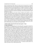
The structure of CBCF is shown in the
SEM
micrograph in Fig.
4.
The crenellated
surface of the rayon derived carbon fibers is clearly visible, as is the phenolic
derived carbon binder. The preferred orientation of the fibers (resulting fiom the
slurry molding operation) is obvious in Fig.
4,
and imparts considerable anisotropy
to the material. The molding direction is perpendicular to the plane of the carbon
fibers in Fig.
4.
Fig.
4.
An
SEM
micrograph
of
CBCF
revealing its structure
and
texture.
Several stringent requirements must be met by the thermal insulation of the GPHS
[l],
chief amongst these are: light-weight; long-term thermal stability and an
ability to withstand thermal transients to -2500°C; chemical compatibility with
other components of the GPHS; low gas evolution, in order not
to
damage the Si-
Ge thermoelectric couples; and sufficient mechanical strength to survive launch
induced vibrational stresses. Moreover, the thermal conductivity must be low
enough to protect the iridium alloy clad in the manner described above. The use
of CBCF thermal insulation in the GPHS reduces the weight of the overall system
by
1.4
kg, and increases the specific power by
7%
[9]
over previous space nuclear
power systems or other designs of the GPHS utilizing more conventional insulation
materials.
175
3.2
Physical Properties
Wei and Robbins
[
101 and Brassell and Wei [2] have reported property data for
CBCF. Their
data,
and more recent unpublished data from
ORNL,
are summarized
below.
3.2.1
Density
In
an early study [lo] of the density of CBCF forms, a series of 26 tubes
(-
10 cm
in
length, and with
an
outside diameter
of
-4 cm and an inside diameter of -3
an),
and
6
plates
(-
10
x
10
x
2.5
cm), were examined. The bulk density, determined
from the dimensions
and
the
mass
of the outgassed forms, varied from 0.19 to
0.27
g/cm3. The density was reported to be a function of packing of the fibers
in
the
composite, which
is
in
turn
primarily a function
of
the fiber length and length
distribution. The variation
of
density
within
a single CBCF plate was examined by
Weaver and Chilcoat
[l
11.
The plate was cut into
80
specimens and the density
determined by mensuration. The density varied from 0.2322
-
0.2493 g/cm3, a
variation
of
about
7%.
There was a tendency for the density to be slightly lower
in
the periphery
of
the plate. Density measurements performed on CBCF tubes by
repetitively machining the outside diameter and re-weighing the tube, revealed a
higher density in the inner and outer
skin
of
the
tube,
where the density was
-
10%
higher than
in
the center
of
the tube wall
[
111.
3.2.2 Mechanical properties
The mechanical properties of CBCF have been determined at ORNL[lO].
Compressive strengths were measured at a cross-head speed of
8.5
pmfs
using
samples core drilled from plates or cylinders.
In
the direction perpendicular to the
fiber (molding direction) the load-deflection curve
is
linear up to approximately
4%
strain. Above 4% strain and up to approximately
40%
strain, the load-deflection
curve
is
typically concave downward.
As
discussed by Wei and Robbins [lo],
elastic deformation occurs up to about
4%
strain, after which structural degradation
occurs. The strength of the CBCF was arbitrarily defined as the stress at
5%
strain.
Over 100 samples taken from multiple fabrication
runs
were tested. The
compressive strength in the molding direction ranged from
0.52
to 1.12 MPa, and
sample density varied from 0.19 to 0.25 Mg/m3. The strength data are plotted
in
Fig. 5. The scatter
of
the strength data
is
large, but there is a clear trend for
increasing
strength
with increasing density, which has been attributed to increased
bonding between the fibers at greater densities
[lo].
Compressive strengths
measured on specimens cut from three CBCF tubes
[l
11 ranged from
0.774
to
0.958 MPa, similar to the strength reported by Wei and Robbins [lo] for CBCF
plates. The shear strength
of
CBCF (measured in the direction perpendicular to the
fibers at room temperature), was reported to be 0.59 MPa, which
is
significantly
less
than
the compressive strength.
176
u
$
180
+
v)
g
120
-
.
cn
w
a
80
a
8
V
-
40
6
:
m.
.
0.
.
'
1.5
i.0
-
a
3
U
-
0.5
The elastic modulus of
CBCF
(calculated fiom the stress-strain curves) ranged
from
11-28
MPa
in
the molding direction
[lo].
The relatively low elastic modulus
bestows excellent thermal shock resistence to the
CBCF.
The elastic modulus and
compressive strength of
CBCF
in the direction parallel to the fibers (perpendicular
to the moldmg direction) are typically
four
times greater than those in the molding
direction (perpendicular to the fibers). This anisotropy
can
be attributed to the
preferred fiber orientation that develops during the molding operation (Fig.
3).
Thermal effects
on
the strength and modulus
are
reported
to
be negligible up to
1200°C
(in
vacuum or an inert gas)[lO]. Indeed, both the strength and modulus
were slightly greater at
1200°C
than at room temperature. Moreover, prolonged
high temperature exposure
(1000
hours at
1350°C)
had
no
effect
on
strength,
3.2.3
Thermal properties
Wei and Robbins
[
101
have reviewed much
of
the work performed on the thermal
physical properties of
CBCF.
The emissivity parallel to the fibers was
0.8
over the
temperature range from 1000 to
1800°C.
This value is higher than the emissivity
of
c-direction pyrolytic graphite
(0.5-0.6),
but
is
close to values for graphite and
dense carbon-carbon composite
(0.8-0.95).
The thermal expansion
of
CBCF
is greater
in
the direction perpendicular to the
fibers than
in
the parallel direction by a factor
of
-
1.4. The mean coefficients
of
thermal expansion
(CTE)
from room temperature to
1800°C
were
3.9
x
10-6/"C
(perpendicular to the fiber direction) and
2.8
x
10-6/oC
(parallel to the direction
of
177
the fibers). These values are lower than those of many fie-grained graphites.
Moreover, the perpendicular direction CTE is lower than the correspondmg value
for a dense carbon-carbon composite, whereas the parallel to fiber dlrection
is
significantly greater than those for dense carbon-carbon composites measured in
the corresponding direction [12]. The specific heat of CBCF, measured using a
scanning calorimeter, varied fi-om 684 JkgeK at 23°C to 2150 J/kg*K at 2000°C
which agrees with specific heat data for POCO graphite
[
121.
Thermal conductivity is
a
function of the specimen orientation, due to the preferred
alignment of the fibers during molding (Fig. 3), and of the carbonization
temperature. For example, increasing the carbonization temperature from 1300 to
1600°C increased the thermal conductivity by -30%. Moreover, the anisotropy
factor for thermal conductivity
is
-5 over the temperature range from room
temperature to 2000°C. Measured values of thermal conductivity (at room
temperature
in
vacuum) ranged from 0.0422 to 0.0863 W/m*K for samples with
densities varying from 0.20
to
0.25 &m3. The room temperature conductivity was
found
to
exhibit a linear dependence
on
density. Weaver and Chilcoat
[
111
reported the room temperature thermal conductivity within a plate varied from
0.0608 to 0.0757 W/m-K, in good agreement with Robbins and Wei [lo].
The temperature dependence of the thermal conductivity of CBCF has been
examined by several workers [10,13,14]. Typically, models for the thermal
conductivity behavior include a density term and
two
temperature
(T)
terms, i.e.,
a
T
term representing conduction within the fibers, and a
T
term to account for the
radiation contribution due to conduction. The thermal conductivity
of
CBCF
(measured perpendcular to the fibers) over the temperature range
600
to 2200
K
for four samples
is
shown
in
Fig. 6
[
141. The specimen to specimen variability in
the insulation, and typical experimental scatter observed in the thermal conductivity
data
is
evident in Fig. 6. The thermal conductivity of CBCF increases with
temperature due to the contribution from radiation and thermally induced
improvements in fiber structure and conductivity above 1873
K.
Recently, Dinwiddie
et
al.
[
141 reported the effects of short-time, hgh-temperature
exposures on the temperature dependence of the thermal conductivity of CBCF.
Samples were exposed to temperatures ranging from 2673 to 3273
K,
for periods
of 10, 15, and 20 seconds, to examine the time dependent effects of graphitization
on thermal conductivity measured over the temperature range from 673 to 2373
K.
Typical experimental data are shown
in
Figs. 7 and 8 for exposure times of 10 and
20 seconds, respectively. The thermal conductivity was observed to increase with
both heat treatment temperature and exposure time.
178
g
0.4
s
3
0.3
c
0.2
I
-
0
=I
'El
0
0
-
g
0.1
ar
r
I-
0.0
As
Fab'ed
0
0-54-4E
0
0.51-4E
A
6-49-IE
-
-
-
-
1
I
I
I
I
I
I
Fig.
6.
The temperature dependence of thermal conductivity for CBCF
in
the
"as
fabricated"
condition. Reprinted from
[14],
copyright
0
1996
Technomic Publishing Company, hc.,
with permission.
Oa7
'
t'=5.7'!hConds'
'
'
'
'
'
*
'
'
' '
I
'
'
I-
Tom6!
0
Tm=3U73K
-
,r
rc
__.
.
13
T,=
3273
K
A
T,
=
2873
K
v-
~
l I I I.,.l l1
400
800
1200
1600
2ooo
2400
Temperature
(K)
Fig.
7.
Thermal conductivity data
for
CBCF specimens heat treated for
10
seconds
(5.7
seconds at temperature) at four different tcmperatures. Solid lines are predicted curves from
Eqs.
(5)
through
(8).
Reprinted from
[14],
copyright
0
1996
Technomic
Publishing
Company, Inc., with permission.
179
t
.,I.
I
.I*,
I
,.,.
I
1
I
,
4.1
400
800
1200
1600 2000 2400
Temperature
(K)
Fig.
8.
Thermal conductivity data for
CBCF
specimens heat treated for
20
seconds
(15.7
seconds at temperature) at four different temperatures. Solid lines are predicted curves
from
Eqs.
(5)
through
(8).
Reprinted from
[14],
copyright
0
1996
Technomic Publishing
Company, Inc., with permission.
Dinwiddie
et
al.
[
141
proposed a model for the behavior of the CBCF in which the
temperature dependence of thermal conductivity
(A,)
may be expressed as
kT
=
Afsks
+
kR
+
kG
(1)
where
A
is the fraction of heat transfer
in
the parallel mode,
fs
is the volume
fraction of solid (assumed to be approximately
0.1
for production CBCF),
As
is
the
thermal conductivity of the solid carbon (fiber and binder),
A,
is the thermal
conductivity contribution due to the presence of the gas phase with the specimen
(neglected by Dinwidde
et
aZ),
and
AR
is the effective thermal conductivity due to
rahation, and is given by
where
n
is
the index of refraction (equal to
l),
o
is the Stefan-Boltzmann constant
[5.6697
x
lo-'
W/(m2-K4)],
o,
is the extinction coefficient for CBCF, and Tis the
absolute temperature.
In
a previously unpublished work by Eatherly
[
151,
the value
of
0,
was taken as
14000
m-'. This value was also adopted by Dinwiddie
et
al.
in