Carbon Materials for Advanced Technologies Part 7 pptx
Bạn đang xem bản rút gọn của tài liệu. Xem và tải ngay bản đầy đủ của tài liệu tại đây (546.38 KB, 35 trang )
190
5.3
Physical
Properties
Typical physical properties of
our
CFCMS monoliths are given in Table 3. The
exact value of a parbcular property is dependent upon the fabrication route,
composition, density, etc. Consequently, property ranges are given
m
Table 3
rather than absolute values.
Table
3.
Physical properhes
of
CFCMS monoliths developed
by
ORNL/UKCAER
property Value
~
Density, g/cm3
0
2
-
0.4
0
4-1
O*
Compressive strength, MPa
1-3
Electrical resistivity, d*cm
Thermal
conductmty,
W/m*K
130
@
density
of
0
25
g/cm3
0.14
@
density
of
0.25
g/m3
*
hot-pressed density range
The effect of fiberbinder ratio on the density and strength
of
the isotropic pitch
derived fiber monoliths was examined
[23]
in
a study
111
which the raho of
P200
fibers was increased by factors of 2,
3,
or
4,
from the standard fiberhmder ratio.
The density
was
seen to decrease from
-0.38
g/cm’ for the standard formulation
to
-0.36
gkm3 for the
4X
fomulahoa
A
slight reductmn
in
compressive strength,
from
-
1.9 to
-
1.7 MPa, was observed to accompany the density reduchon,
although the scatter in the data made it impossible to develop a density-strength
conelabon. Dmg activatlon the carbon is selectively gasified, resultmg
111
a
mass loss
m
the monolith. The compressive strength
(uc)
is degraded by this
mass
loss and follows the relahonshp
[
19,231:
(9)
oc
=
1.843exp(-O.O1323x)
where x is the fracbonal weight loss or burn-off.
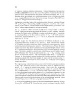
The
electncal behavior of
CFCMS
IS
shown
~tl
Fig. 17(a). The current-voltage
relationship is linear and the electrical resistwity of the monolith
in
Fig. 17(a)
(2.5
cm
in
diameter and
7.5
cm
in
length) was 130 d-cm
[23,24].
The resistivlty of
the monolith is considerably greater than that of the carbon fibers, whch according
to
the manufacturer’s product literature
1s
4-6
mS2.cm. The poorer electncal
conductivity of the monolith can be attributed to the large electncal resistance
associated with the fiberibmder interface.
A consequence
of
the passage of an
electric current through the monolith is resistwe (ohrmc) heatmg. Figure 17(b)
191
shows the temperature of a monolith as a function of the electrical power input
(product of the applied voltage and induced current). At relatwely low power
inputs, the monolith readily heats to 50-100°C, and temperatures >300°C are
rapidly attained at a power input of -45
W.
16
14
c
12
=:8
E6
5
019
2
E"
10
Q
E
%1234
Voltage
(Volts)
400
-
Sample
214b
350
-
5.9%
bumoff
(25
4
mm
dia.
x
762
mm
ten
)
Power
(Watts)
Fig.
17.
The voltage-current relationship (a)
and
resistive heating
curve
(b)
for
a
CFCMS
monolith (sample
21-2B,
18%
burn-off, 2.5-cm diameter
x
7 5-cm
length)
[23]
Data for the thermal conductivity of adsorbent carbons are somewhat limted
[23].
Typically, a bed of granular carbon at a packed density of
-0.5
g/cm3 has a thermal
conductwity
of
0.14-0.19
WImK,
while the denved value for the carbon adsorbent
is normally between
0.6
and
1.3
WlmK.
CFCMS monoliths typically have
comparable thermal conductivities
to
a packed bed, but at substantially lower
density (Table
3).
The greater specific thermal conductivity of the monoliths can
be attributed to the substanhally higher thermal conductwity of the carbon fibers
(2-5
W/mK),
whch results
from
the higher density of fiber compared to GAC (1.6
g/cm3 cf.
0.6
g/cm3), and the reduced contact resistance between the fibers
in
the
case of the bonded fiber monoliths. For many applicabons increased thermal
conductmty is
an
extremely desirable attriiute for a bed of adsorbent carbon. The
flexible process by which CFCMS is manufactured allows the blending of high
conductivity mesophase pitch-derived carbon fibers into the material. Moreover,
hot pressmg the monolith after drylns allows the density and thermal conductivity
to
be increased substantially. To assess the extent to which the thermal
conductwity could be enhanced by blendmg
m
mesophase pitch-denved carbon
fibers, andor by increasmg the bulk density, a series of expermental hybrid
monoliths were fabricated. Table
4
reports the compositlon, density, and room
192
temperature thermal conductivities of the monoliths.
Table
4.
Room
temperature thermal conductivity
of
hybrid monoliths
at
normal and hlgh
density.
Thermal conductivity
Specimen
wt
%
of
DKDX Density at
25°C
(W/mK)
ID fiber
Wm3
1
/I
to
fibers
.L
to
fibers
KO-A
0
0
61
0.250
0
07
K2-A
11
0.65
0.485
0
14
K3-A 18 0.63
0.93 0.15
KO-B
0
0
21 0.05
0
02
KO-B
11
0
22 0.12
0.04
KO-B 18
0.26
0.19
0
07
Several significant trends emerge from the data
in
Table
4.
Fmt, the thermal
conductivity is greater in the
1)
to fiber dlrection than in the
I
to fiber du-ecbon.
This is expected from the preferred orientation
of
the fiber that develops durmg
molding. Second, the thermal conductivity is strongly dependent upon the density.
For example, at a density of 0.2
1
g/cm3 the thermal conducbvity
(11)
is only
0.05
W/mK,
rising to
0.19
W/mK
at a density of 0.26 gkm’
,
and 0.25
W/mK
at a
density of
0.61
g/cm3. Finally, the thermal conductivity (both
I/
and
I)
increases
as the fraction
of DKDX
fiber
m
the hybrid monolith increases. At a loadmg of
18%
DKDX
fibers, the thermal conductivity
(11)
is increased to
0.19
W/mK
at a
density of 0.26 g/cm3 and
0.93
W/mK
at a density of 0.63 g/cm3.
Ths
latter value
represents a six-fold increase over the thermal conducbvity of the standard CFCMS
monoliths and a four- to suc-fold mcrease over the thermal conduchvity of a packed
bed of
GAC.
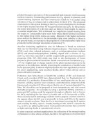
The temperature dependence of the thermal conductivity
(11)
of the
hybrid monoliths is shown in Fig.
18.
The thermal conducbvity increases
with
temperature over the range
30-500°C
due to the increasing contnbubon of
radation conduction
m
the pores (see the discussion in Secbon
3
of this chapter).
An increased thermal conductivity in a carbon bed will reduce temperature
gradients, qrove efficiency and, for a storage carbon, will increase the delivered
capacity of gas.
If,
however, the mcreased thermal conductivity is accompanied
by a large reduction in bed adsorpbon capacity, the potential performance gain may
be totally offset by the capacity loss penalty. To assess the extent, if any, of this
potential penalty the hybrid monoliths were activated via the
0,
chemisorptiodactivabon process and their micropore structure examined. Table
5
reports micropore characterizabon
data
for the hybrid monoliths (standard and
193
2.50
2.25
-
2.00
-
Y
E
1.75
-
2
high density).
A
comparison of the surface area and micropore volumes for the
base case
(KOAKOB)
and the hybrid monoliths suggests that there is little or no
difference (at comparable bum-offs). Moreover, the micropore data for large
monoliths (Table
2)
compare favorably with the data
in
Table
5
for the standard
density hybrid monoliths. It should also be noted that for storage applications a
high volumetric micropore capacity is desirable, i.e., micropore volhnit volume
of storage vessel.
-0-
KOA
0%
DKDX fibers
-D-
K2A
11% DKDX fibers
-A-
K3A 18% DKDX fibers
+
KOB
0%
DKDX fibers
-0-
K2B
11% DKDX fibers
-0-
K3B
18% DKDXfibers
0
100
200
300
400
500
Temperature,
OC
Fig.
18.
The temperature dependence
of
the thermal conductivity
of
hybrid carbon fiber
monoliths measured
in
the
II
to fibers direction at
two
densities.
The
high
density hybrid monoliths would thus appear to
be
well suited to storage
applications. However, the data presented here are for hybrid monoliths that are
far
from
optimum
as
storage carbons. A great deal of development work is
required to increase the micropore volume and storage capacity
of
the monoliths.
Some of
our preliminary work
in
this
context is discussed subsequently.
194
Table
5.
Micropore characterization data for
hybrid
monoliths
at
two
densities.
Pre-activation.
Specmen density
%
DKDX
Bum-off
BET
area
DR
pore
ID
Wm’)
fibers
(“w
(mZ
49
vol.
(cm’k)
KOA 0.67
0
5.5 429 0.16
K1A 0.62 5 72 406
0
16
K3A 0.69 18 43 307
0
12
KOB 0.21
0
56
445
0
16
KlB 0.22
5
94 540
0.21
K3B 0.25
18 5.3 429 0.17
5
4
Gas adsorption and separation
The gas adsorption behavior
of
our
monoliths has been studied as part of the
U.S.
Department of Energy’s ongoing Fossil Energy Advanced Research Program. The
equihbrium adsorption of CO, and CH, was found to be strongly temperature
dependent, and the uptake of CO, was greater than the uptake
of
CH, for
a
given
specimen
[23].
For example, volumetric measurements at 30°C and one
atmosphere, on CFCMS with moderate burn-off, showed that approximately
50
cm3/g
of
CO, were adsorbed, whereas only approxmately
27
cm3/g
of
CH, were
adsorbed. High pressure
[0.5-59
bar
(8-850
psi)] CO, and CH, isotherms are
shown
in Fig.
19
for monoliths
21-1
1
and
21-2B,
which had
9
and
18%
burn-off,
respectively. The measured volumetric and gravmetric (Fig.
19)
adsorption
capacities at one atmosphere for both CH, and CO, are
in
good agreement for the
CFCMS specmens. At one atmosphere, approxmately
100
mg of CO, per g
of
CFCMS and approximately
19
mg of CH, per g of CFCMS were adsorbed. The
quantihes
of
gas adsorbed rose to
>490
mg/g (CO, on specimen
21-2B)
and
>67
mg/g (CH, on specimen
21-2B).
Moreover, the CO, isotherms are still mcreasmg
with pressure whereas the CH4 isotherms have flattened (i.e., the CFCMS has
become saturated with CH,). The data in Fig.
19
clearly show that CFCMS
exhibits selective adsorption of CO, over CH,.
195
500
0'
0
200
400
600
800
1000
Pressure (psia)
Fig.
19.
High
pressure
isotherms at
25
C
of GO,
and
CH,
for
CFCMS
monoliths.
The CO, adsorpbon data discussed above suggests that CFCMS mght provide an
effechve media for the separabon of CO, from CH,.
To
determine the efficacy
of
CFCMS for this purpose, several steam achvated samples were tested in a
breakthrough apparatusC23-2.51.
A
typical breakthrough plot for a CH,/CO,
murture is shown
m
Fig.
20.
The specimen is heated electslcally and any entrained
air
is
initially dnven out with a He purge. The mput gas
is
then switched
to
a 2:
1
mixture of CH,/CO, at a flow rate of 0.33 slpm.
The outlet stream
He
concentration decreases and the CH, concentration increases rapidly (i.e., CH,
breaks through). Adsorption of CO, occurs and, therefore, the CO, concentrahon
remains constant at a low level for apprownately six minutes before the CO,
concentration begins
to
increase, i.e., CO, -breakthrough occurs. Table
6
reports
data
from
a prelminary study of CO, separation. CO, capacibes are reported as
determined
from
pure CO, and CO,/CH, mixtures
on
each speclmen examined.
The reported CO, capacibes are the means of several repeats of the breakthrough
expenments, and the
BET
surface and other microporosity charactenzation data are
addiQonally given
m
Table
1.
Two of the CFCMS samples (lowest bum-off) had
CO, adsorption capacities of almost one liter on 0.037 bters of adsorbent, and
only
a small capacity reduction was observed in the COJCH, gas murture The
CO,
adsorption capacity decreases with mcreasing burn-off,
in
agreement with the
isotherm data.
196
-9
n
c
-10
Q)
S
0
0
u)
L
L
c
-11
.I
W
5
-12
Flow
rate
0.33
slpm
Gas
composition
2:l
Breakthrough
*
Time
II
I
II
I
I
I
0
3
6
9
12
15
18
-1
3
Time
(min)
Fig.
20.
Typical COJCH, breakthrough plot for CFCMS monolith sample
21-1
1
(9%
bum-
off)
at
25°C
Table
6.
CO, seoaration data
from
our
CO, and COJCH, breakthrough exoeriments.
Specimen Bum-off BET Surface CO, Capacity (Liters)
No
(%>
Area (m’/g)
CO,/CH,
CO,
only
21-1
1
9
512
0.73
0
97
2
1
-2B
18
1152
0.45
0.98
2
1
-2D
27 1962
0
39
0.80
2
1
-2c
36 1367 0.35
0
80
A
typical
H,S/H,
breakthrough plot is shown in Fig.
21
for a gas composition of
5.4%
H,S,
14%
Ar,
with the balance bemg
H,
.
The
H,
(not shown
111
Fig.
21)
is
not adsorbed, whereas the
H,S
is held on the carbon, producing a
H,S
free
H,
stream for approxmtely
18
minutes.
In
Fig.
21
the
H,S
concentrahon can be seen
to increase sharply after breakthrough is completed The concentration mcrease
197
coincides with the applicatlon of a d.c. electrical voltage
(4-5
amps at
1
volt) and
the He purge gas.
H2S
desorption occurs over a relatively
short
tune
(1
8
minutes).
The
H,S
adsorption capacity (at atmospheric pressure) for sample
21-1B, 18%
burn-off, was
0.43
liters (Fig.
21).
Flow
rate
=
0.44
slpm
Gas
composition:
HPS
5.4%
Ar
14.0%
Fig.
21.
A
typical
H2S
breakthrough
plot
for
a
CFCMS
monolith
21-2B
(1
8%
bum-off)
at
25°C
CFCMS
has a continuous
3D
carbon structure (Fig.
11)
which imparts electncal
conductivity to the material. We have utilmed the electrical properties of CFCMS
to affect a rapid desorption
of
adsorbed gases
in
our
breakthrough apparatus. The
benefit
of
this technique is
shown
m
Fig.
22,
which shows the
CO,
and
CH,
gas
concentrations
in
the outlet gas stream of our breakthrough apparatus
[23-251.
Three adsorptionidesorption cycles are
shown
~fl
Fig.
22.
In
the fist and second
cycles
(A
and
B
in
Fig.
22)
desorption is caused by the combined effect of an
applied voltage
(1
volt) and a He purge gas.
In
the third cycle
(C
in Fig.
22)
desorphon is caused only by the He purge gas.
A
comparison
of
cycles
B
and
C
mdicates that the applied voltage reduces
the
desorptlon tune
to
less
than
one third
of
that for the He purge
gas
alone (cycle C). Clearly, the desorphon of adsorbed
C02 can
be
rapidly induced
by
the apphcabon
of
a
d.c. electncal potenfial.
198
-9
-10
.cI
c
Q)
L
L
j
-11
C
0
.I
v
-12
J
Gas
mixture
2:l
CH4ICO2
I
0
24
48
72
96
120
144
168
192
Time
(min)
-1
3
Fig.
22.
CO,/CH,
breakthrough plots
for
CFCMS
sample
2
1
-
1
F
(1
0%
bum-off)
showing
the
benefit
of
electrically enhanced desorption:
A.
1
volt,
He
purge
@
0
4
slpm;
B
1
volt,
He
purge
@?
0.06
slpm,
and
C.
0
volt,
He
purge
0.06
slpm
Increased adsorbent (CFCMS) temperature results
m
desorphon of the adsorbate.
However, desorption occurs mediately when the voltage is applied to the
CFCMS, whereas the bulk temperature increase lags the apphcahon of the voltage
by a finite time, typically several minutes
[23].
Evidently, the resistance heatmg
effect
is
acting directly at the adsorption sites (fiber mcroporosity) resulting
m
a
rapid desorption of the adsorbate. The heat of adsorption of CO, on activated
carbon fiber is
30
kJ/mol
[30].
A
simple calculation for the a typical ESA
breakthrough experiment, where approximately
1
litre
of
CO, was adsorbed,
mdicates that at a power level of
5
Watts, approxunately
270
seconds would be
required to mput the energy
(1350
J)
required to desorb the C02 adsorbed on the
CFCMS. Implicit
in
this calculation is the assumption that all of the electrical
energy
is
converted to thermal energy and transferred to the adsorbed CO,. Whlle
this analysis is very smplistic, it does explam the observation of a tme lag
between the inihation of electrical current flow and the CFCMS temperature rise
during the electrical desorpfion of adsorbed gases. Actual measured desorphon
tunes are of the order of
6-13
minutes, depending on the purge gas flow rate (Fig.
22).
Therefore, other factors must lnfluence heat flow to the adsorpfion sites in the
199
carbon fibers. Several explanations have been postulated, the most plausible of
which is based on the compensating effect of the heat of adsorption and the
temperature dependence of electrical resistivity in carbon
[23].
The ability of CFCMS to selectwely adsorb a gas from a gas rmxture, combined
with the electncally enhanced desorpbon of the adsorbed species, allows for a gas
separabon system where the separation is effected by electrical swmg
(ES)
rather
than the more conventional pressure or temperature swings. Several applicahons
of CFCMS/ES can be considered. For example: (i) the cleanup
of
sub-quality
natural gas;
(ii)
the separation
of
hydrogen from coke oven battery reformer waste
gas streams; (iii) the separation of landfill gases; and (iv) a guard bed for the
removal of higher hydrocarbons, or sulfur bearlng odorants, from
CH,
fuels
in
adsorption storage fuel tanks or solid oxide fuel cells. Moreover, the novel
combmation of properties make CFCMS attractive for adsorption gas storage
systems where the delivery of adsorbed gasses can be hindered by excessive
temperature drop in the carbon adsorbent due to the large heat of adsorption.
A
variant of the CFCMS monolith with appropriately developed microporosity, and
a buk density
-
1
.O
g/cm3, would be expected to posses a storage volume equal to
or greater than currently available
CH,
storage carbons. Fmally, a mesoporous
variant
of
CFCMS might offer advantages as a catalyst
support
for reforming
operations because heating of the
support
could be effected directly by the passage
of
an electric current, negatmg the need to preheat the reactant gasses.
5.5
Near term applications
Two particular applications of CFCMS monoliths can be considered near term.
The
first,
fighting vehicle air clean-up (with respect to NBC contarmnants), would
appear to be an eminently suitable field for
our
adsorbent fiber-based monohths
Several attributes of the monoliths should be considered in this context: (1) the
monohths are rugged and
wll
not suffer attntion under the harsh terrain condihons
encountered by fighting vehicles; (ii) the micro/meso pore structure can be
controlled by appropnate selecbon
of
the fiber type and processmg/activation
route;
(iii)
ESA would appear to offer a rapid and low energy
desorptiodregeneration method, compared to pressure swing or thermal swing
regeneration for the adsorbent bed; and (iv) the defense market could stand the
higher cost of the monoliths compared to granular carbons. The second near term
application of
our
adsorbent monoliths is in a guard bed for a solid oxide fuel cell
(SOFC)
[7,27].
Westinghouse solid oxide fuel cells utilize CH, and air
as
fuels
[31]
Operatmg experience with the cells
has
demonstrated an efficiency
degradation associated with the interaction of the
sulfur
bearing odorants
in
the
natural gas and the ceramic materials used
m
the construction
of
the cell.
Thls
has
necessitated the use of a large GAC guard bed, which must be replaced when
saturated.
A
compact, easily regenerated guard bed has obvious advantages over
200
6-
I
I
I
I
I
I
I
5
-
0
SMW-3
-
the large GAC bed currently employed.
In
a collaborative venture, a guard bed
assembly containing three monoliths (IO-cm diameter and 25-cm length)
in
separate canisters was fabricated and
1s
currently under evaluation at Westinghouse
Science and Technology Center, Pittsburgh,
USA.
The carbon fiber monoliths
were prepared
from
P200 fibers and acavated via the oxygen
chemisorptlodactivation route
[7,27].
Pnor
to
delivery to Westinghouse, the
pressure
drop
through
the monoliWcanister was measured, and
is
shown
ln
Fig.
23.
ON
=4
d
I
h
&3
U
E
*2
UI
a
L
1
0
17
SMW4
17)
Q
-
cp
-
0
W
-
cp
-
B
I
I
I
I
I I I
10
15
20
25
30
35
40
5
Outlet
fow
rate,
sipm
Fig.
23.
Pressure
drop
through a large
monolith
as
a
funchon
of
He
flow
rate
[27].
The measured pressure
drops
were slightly greater than literature data would
lndicate for packed carbon beds. However, they are certainly
not
prohibitwe and
a successful outcome
of
the Westinghouse trial
of
the
SOFC
guard bed is
anticipated.
6
Summary
and
Conclusions
Porous carbon fiber-carbon bmder composites are a class of matenals that are not
widely
known,
yet they
f%lfill
a vital role
in
the
RTG
space power systems,
and
show considerable potential for other uses
in
light absorption or gas adsorption
applicatlons. These applicabons are enabled through the unique combmation
of
physical prope&es exhibited by the porous carbon fiber-carbon binder composites
Perhaps the most sigmficant
of
its physical attributes
is
the
open,
yet rugged, form
of the material which contributes significantly to its ublity
m
the fields
of
20
1
application discussed previously. In addition, the ability to tailor other physical
properties enhances the potential utility
of
hs
class
of
carbon composite material.
The pore structure
of
the material, which is
of
paramount importance in fluid
separation and gas storage applications, can be controlled through careful selection
of
the precursor carbon fiber and processing and activation route. It is likely that
new applications
of
porous, adsorbent, carbon fiber based monoliths will be
developed
in
the near term. These applications will be less cost sensitive than
many current applications
of
commodity GAC, but will be applications
in
whch
the novel properties
of
porous carbon fiber-carbon binder composites make them
uniquely suited. Current research at
ORNL
is
directed toward improving the
uniformity, and key properties
of
the material, and at containing, or reducing, the
cost
of
our
porous carbon fiber-carbon binder composites.
7
Acknowledgments
Research sponsored by the
U.
S.
Department
of
Energy under contract DE-ACOS-
960R22464
with Lockheed Martin Energy Research Corporation at Oak Ridge
National Laboratory.
8
References
1.
2.
3.
4.
5.
6.
7.
8.
9.
10.
Ardery,
Z.L.
and Reynolds, C.D., Carbon fiber thermal insulation.
Y-12
Report
1803,
Oak
Ridge Y-12 Plant, Oak Ridge
TN,
1972.
Brassell, G.W. and Wei, G.C., High temperature thermal insulation,
In
Proc. 14th
Biennial
Con$
on
Carbon,
American Carbon Society, 1979, pp. 247 248.
Donnett,
JB
and Bansal, R.C.,
Carbon Fibers,
2nd edition, Marcel Dekker, Inc.,
New York, 1990.
Jagtoyen, M. and Derbyshire,
F.,
Carbon fiber composite molecular sieves for gas
separation. In
Proc. Tenth Annual
ConJ
on
Fossil Energy Materials,
CONF-
9605167,0RNWFMP-96/1.
Oak
Ridge National Laboratory, 1996, pp. 291
300.
Nandi,
S.P
and Walker, P.L. Jr., Carbon molecular sieves from the concentration
of oxygen from air,
Fuel,
1975, 54, 169 178.
Quinn, D.F. and Holland, J.A.,
US
Patent No. 5,071,820, 1991.
Burchell, T.D., Judkins, R.R. and Rogers, M.R.,
A
carbon fiber based monolithic
adsorbent for gas separation.
In
Proc. 23rd Biennial
Con$
on
Carbon,
American
Carbon Society, 1997, pp. 158 159.
Angelo, J.
A.
and Buden,
D.,
Space Nuclear Power.
Orbit Book Company, Inc.,
Malabar,
FL.,
1985.
A.
Schock, Design evolution and verification of the general purpose heat source.
In
Proc.
of
15th Intersociety Energy
Conv.
and
Eng.
ConJ,
vol. 2, ASME, New
York, 1980, pp. 1032 1042.
Wei, G.C. and Robbins JM., Carbon-bonded carbon fiber insulation
for
radioisotope space power systems,
Ceramics Bulletin,
1985,64(5),69
1
699.
202
11
12.
13
14.
15.
16
17.
18
19
20.
21
22.
23.
24.
25
26.
27.
28.
Weaver, CE. and Chilcoat, B.R., Carbon-bonded carbon fiber for space
applicahons. Paper presented at the 1994 American Carbon Society Workshop,
Oak
Ridge,
TN.,
May 15-18, 1994.
Burchell, T.D., and Oku, T., Material properties data for fusion reactor plasma
facing carbon-carbon composites,
Nuclear Fusion,
1994, 5(Suppl.), 77 128.
Skrabek, E.A., High temperature msulations for radioisotope thermoelectric
generators. In
Proc. of 13th Intersociety Energy Conv and Eng Con$,
vol. 2,
ASME, New York, 1978, pp, 1712 1716.
Dinwddie, R.B., Nelson, G.E., and Weaver, C.E., The effect of sub-minute high
temperature heat treatments on the thermal conductwity
of
carbon-bonded carbon
fiber (CBCF) insulation.
In Proc. Thermal Conduchvity 23,
ed. K.E. Wilkes, R.B.
Dinwiddie and R.S. Graves, Technomic Pub. Co., Inc., Lancaster, PA, 1996, pp.
466 477.
Eatherly, W P., Some considerations
on
the thermal conductivity of CBCF,
ORNL
Internal Report, October 3
1,
1983.
Lauf, R.J., Hamby, Jr., C., Akerman, M.A
,
and Seals,
R
D.,
US
Patent
No.
5,243,464, 1993.
Lad, R.J., Hamby, Jr., C., Akerman, M.A., and Tnvelpiece, A.W.,
US
Patent
No.
5,313,325, 1994.
Broadband ophcal absorber,
Photonics Spectra,
1994,28(5), 85.
Burchell,
T.
D.,
Carbon fiber composite molecular sieves.
In
Proc. Eighth
Annual Conference
on
Fossil Energy Materials,
ORNL/FMP-94/1, CONF-
9405143,
Oak
Ridge National Lab,
U.S.A.,
1994, pp 63 70.
Burchell, T.D., Weaver, C E., Derbyshire, F., Fei, Y.Q. and Jagtoyen M., Carbon
fiber composite molecular sieves:synthesis and charactenzahon.
In
Proc. Carbon
‘94,
Granada, Spain, Spanish Carbon Group, 1994, pp.
650
65 1.
Derbyshire,
F.,
Fei, Y.Q., Jagtoyen, M., Kimber,
G.,
Matheny, M. and Burchell,
T., Carbon fiber composite molecular sieves for gas separation. In
“New Horizons
for Materials“ Advances
in
Science and Technology
(edited by P. Vincemni),
Techna Srl, Faenza, Italy 1995, Vol. 4, pp. 41 1 417.
Jagtoyen, M., Lafferty, C., Kimber, G, and Derbyshire, F.,
Novel activated
carbon materials for water treatment. In
Proc The CARBON
‘96
Conf,
1996, pp.
328 329.
Burchell,
T
D., Judkins, R.R., Rogers, M.R. and Williams, A.M A novel process
and material for the separation
of
carbon dioxide and hydrogen sulfide gas
mixtures.
Carbon
1997, 35(9), 1279 1294.
Burchell, T.D., Judkins, R.R, Rogers, M.R. and Williams, A.M.
A
novel
approach to the removal of COP In
Proc Tenth Annual Con$
On
Fossil Energy
Materials,
ORNL/FMP-96/1, COW-9605167,
Oak
Ridge National Lab,
U.S
A
,
1996, pp. 135 148.
Burchell, T.D and Judkins, R.R. A novel carbon fiber based matenal and
separation technology.
Energy Convers Mgmt,
1997,38, Suppl., pp S99
S104.
Burchell, T.D. and Judkins, R.R. Passive
CO,
removal using a carbon fiber
composite molecular sieve,
Energy Convers. Mgmt,
1996,37(6-8), 947 954
Burchell, T D. and Rogers, M.R., Carbon fiber composite molecular sieves, In
Proc Eleventh Annual Con$
On
Fossil Energy Materials,
ORNL/FMP-97/1,
CONF-9705115,
Oak
Ridge National Lab, U.S.A., 1997, pp. 109 116.
Burchell, T.D, Klett J.W
,
and Weaver, C.E. A novel carbon fiber based
porous
203
carbon monolith, In
Proc
Ninth
Annual
Conf On
Fossil
Energy Materials,
ORNLRMP-95/1, CONF-9505204, Oak Ridge Nahonal Lab,
U SA,
1995, pp
447 456.
Klett,
J.W.
and
Burchell T.D., Carbon fiber carbon composites for catalyst
supports. In
Proc
22"d
Biennial Conf
On
carbon,
Pub. Amencan carbon Society,
1995, pp. 124 125
M.
Kuro-Oka,
T
Suzuki,
T
Nitta
and T. Katayama
J
Chem
Eng
ofJapan,
1984, 17(6), 588.
Smgh, P., Ruka, R.J.,
and
George,
R.A
Direct utilization
of
hydrocarbon fuels
in high temperature solid oxide fuel cells, In
Proc
24'h
intersocieiy energy
conversion engineering conference,
Pub.
Institute
of
Electrical and Electronics
Engineers, New York, 1989, pp 1553 1563.
29
30
3 1.
205
CHAPTER
7
C
o
a1
-D
erive
d
Carbons
PETER
G.
STANSBERRY,
JOHN
W.
ZONDLO,
ALFRED
H.
STILLER
Department of Chemical Engineering
West Virginia University
Morguntown,
WV
26.506-6102
1
Review
of
Coal-Derived
Carbons
1
I
Introduction
Complex aromatic raw materials such as petroleum resids, decant oils, coal, and
coal tars have been employed for many years by the carbon industry and
contlnue to be used extensively
in
the fabricahon of coke, carbon, and artlficial
graphite
[
11. These same feedstocks also have the potential for use in producing
"advanced" carbon products such as carbonaceous mesophase, fibers, and beads
[2-41.
Currently, nearly all domestic pitches are obtamed from either coal tar or
petroleum precursors [5] The pitch products, whether petroleum-based or coal-
tar based, are pnzed by the ancillary mdustries that are dependent upon them but
such pitches are, nevertheless, considered to be derived from byproduct
materials.
In
addition, besides being derived from byproducts, the yield of pitch
typically amounts to no more than 5 wt% based on the mihal quantity of coal or
crude feedstock [6].
The key feature that makes commercial pitches attractive and practical to the
carbon industry
is
thelr
highly aromatic nature. It is well
known
that
aromaticity is necessary for the development of planar molecular alignment
during liquid-phase carbonlzation which, m
turn,
is a requirement for
graphitizability
[7,8].
Because coal itself is predominantly aromahc [9], there
has been a resurgence in research focused on producmg extracts and other types
of
pitch-hke substances from coal for other than fuel purposes
[lo].
Depending
on
how
the coal-based material
1s
processed, hghly isotropic
or
anisotropic
carbons can be obtamed
[
1 11
It is expected that produchon
of
coal-derived pitches, liquids, and chemicals will
take on a more important role in the future. This is of some strategic concern to
the United States, where the demand for domestic petroleum is greater than the
supply. Moreover, the quality of imported petroleum crudes is dechmg in that
they contain increasing amounts of contamant metals and
sulfur
In
adhtion to supplying transportabon fuels and chemicals, products from coal
liquefachon and extraction have been used
m
the past as pitches for binders and
feedstocks for cokes
[12].
Indeed, the majority of organic chermcals and
carbonaceous materials prior to World War I1 were based
on
coal technologies.
Unfortunately, this technology was supplanted when inexpensive petroleum
became available during the
1940s.
Nevertheless, despite a steady decline of
coal use for non-combushon purposes over the past several decades, coal tars
still remain
an
important commodity
m
North Amenca.
In recent years researchers at West Virginia University have developed coal-
derived pitches on a laboratory scale in quanhties sufficient to make
1
kg
samples
of
calclned coke for fashonmg graphite test specunens. The pitches
were derived by uhlizmg solvent extrachon with N-methyl pyrrolidone
(NMP).
This solvent is able to isolate coal-based pitches
m
high yield and with low
rmneral matter content
[13].
It is this work that will form the basis of the
lscussion for the later part of this chapter.
1.2
Coke
production
Most of the coke produced in the United States today comes from the hgh-
temperature carbonization of coal. The coke is used primarily by the
metallurgical industries as a fuel and
ln
the renderlng of
lron
from iron ore
m
the blast furnace
Essenhally, carbonlzation entails the heating of organic precursors
m
the
absence of air. In so doing, a solid carbon residue along with gaseous and
volatile hydrocarbons is created. Bituminous coals are used to make
metallurgical-grade coke while wood and other slrmlar substances make
charcoal. The condensed volatile material can be fwther refined to yield
chermcals, pitches, or other useful commodihes.
Historically, the produchon of coke from coal resulted from the pressures
exerted by environmental and economc forces.
In
the late
1500s,
demand for
wood in England began to surpass supply. At that hme, wood was converted
into charcoal for use as a reductant of
zron
ore by the burgeonmg metallurgical
industries. By
1710,
Abraham Darby of Coalbrookdale
ln
Shropshn-e, England,
commercialized the production of pig iron by utrllzmg the coke from coal
207
carbonization. Soon afterward, in only eight decades, over
80
blast furnaces for
iron production were operatmg in Britain. Coal-derived coke was recognized as
a very practical material and was also employed widely for glass makmg,
blacksrmthmg, beer making, and fuel
The practices of charcoal makmg influenced early approaches to coal
carbomzation. The origmal method, though straightforward and somewhat
crude, consisted of simply heatmg mounds of coal on a hearth.
A
better method
of coke productron developed with the appearance of the beehive oven in about
1760 These domed-shaped structures were numerous in the United States with
45 beehive oven plants and over 5,100 beehive ovens ready for operation in
1959 [14]. However, coke productron with these ovens peaked earlier
m
the
20th century A disadvantage
wth
the beehive oven was the lsregard for
collechng the evolving volatile matter while the coal was being heated. The
problem was ameliorated
m
the nineteenth century when coal was carbonized
m
inhrectly heated slot ovens. The mtroduchon of the slot oven led to byproduct
recovery systems and by 1915 thelr use was well established
m
the Urnted
States.
Out of the 900 million tons of coal produced in the United States for domestrc
purposes
m
1992, about 34 million tons were used for coking
[lo].
The
ovenvhelmlng majority of coal is consumed by the electric utdihes.
Nevertheless, in 1990, the United States steel industry required about 23 million
tons of coke which was produced by the byproduct recovery slot oven
[
151 For
a
typical blast furnace, this translates to
0
5
tons of coke per ton
of
iron metal.
Coal carbonizabon is an extremely complicated art. The methods have been
developed through centuries of trial and experience. More detailed descriptions
on the processes involved can be found in the literature
[
161. Modern foundry
or blast furnace coke is made
m
a battery
of
up to
100
slot ovens placed side by
side. Individual ovens are typically 16 meters long, 6.5 meters hgh, and about
0.5
meters
m
width. Each oven holds over 20 tons of coal which is charged
through the top. The oven is sealed and heated induectly through refractory-
lined walls by the hot gases evolved durmg carbonizabon. After about
18
hours, coking is complete with the final temperature reaching over 1000°C. At
the end of the coking cycle, side doors to the oven are opened and a large
pushmg
ram forces the incandescent coke out for quenching. The side doors are
lnstalled agaln and the process repeated. Coke batteries are operated nearly
contmuously to remain productive over thelr life span of 20 to 30 years
Petroleum cokes,
on
the other hand, represent the second largest source
of
consumable industrial carbon in the United States. In 1992, about 2 mllion tons
of anode coke and 250.000 tons
of
needle coke were used in the Umted States.
208
Unlike coke produced from coal, petroleum cokes are derived from the residua
of petroleum refining. Suitable feedstocks for good quality coke are thermal
tars, catalyhc cracker bottoms, and decant oils
[
171.
Several petroleum coking methods have been developed and mclude fluid,
contact, and atmospheric-still cokmg
[6].
The preferred cokmg method used
today is conducted in delayed coking units. Delayed coking is attxachve
because of its ability to produce cokes with controlled mcrostructures One
highly desirable form is known as needle coke
No
coal-based material is
presently processed by delayed cokmg
m
the United States Nevertheless,
delayed coking of coal-tar feedstocks is prachced
m
Japan by the Nippon Steel
Chemical Corporation, and the Mitsubishi Kasei Corporafion.
In delayed coking, an aromatic feed is heated above
400°C
and piped mto the
bottom of one of
two
tall
drums.
As the feedstock fills the coker, thermal
cracking occurs to produce gas, gasolme, oils, and coke. Generally
24
hours are
needed to fill the drum with coke. After the first
drum
is filled, the feed is
mtroduced into the second drum and the next coking cycle begins. Meanwhde
the first
drum
is quenched with steam and then water. After sufficient cooling,
high-pressure water jets drill, cut, and loosen the coke for removal from the
drum.
The emphed coker drum is inspected and prepared for another run.
The coke at this stage is called "green" because it shll contams
5
to
15
wt%
volatile matter. If the coke is to be used as a filler in anode and electrode
manufactunng, this high level of volahle matter is considered unacceptable
because it contributes to shrinkage during subsequent heat treatment and
fabricahon
Removal of volatile matter to about
0.5
wt% can be accomplished by calcmmg
m
a rotary kiln, rotary hearth, or vertical shaft calcmer All of these processes
heat green coke to temperatures in excess of
1000°C
where shrinkage and
subsequent densification take place. The volatile components are comprised
primarily
of
methane, ethane, hydrogen, and hydrogen sulfide gases which can
be employed as fuel for process heat.
1.3
Pitch
production
Coal-based pitches are predommantly byproducts
of
metallurgical coke
operabons in recovery-type coke ovens. The volable products from the coke
oven are recovered and processed, in smplest terms, into gas, hght oils, and tar.
The quanhty and character of the matenals are mfluenced by the type of coal
charge, the design of the coking equipment, and the temperature and
tnne
profile of carbonization. Table
1
shows a typical yleld of products from the
209
carbomzabon
of
a bituminous coal Note that the yield of coal tar is very low.
Despite the low yield, the large volume of coal carbonlzed produces
a
considerable quantity of secondary products.
Table
1.
Production yields
from
coal carbonization
Yield from
1
ton
of
coal
Weight
%
1520
lb coke
76
78
lb
coal tar
4
20
lb
light
oil
1
20
lb ammonium sulfate
1
280
lb gas
14
80
lb
rmscellaneous
4
Crude coal-tar processmg is tradibonally accomplished by distillahon into pitch
and a series of distillate oils. Coal-tar pitch is the material remaining after all
the avadable distdlates are removed The final softening pomt of the coal-tar
pitch can be controlled via the distdlabon condihons.
Coal-tar pitch is particularly valuable to anode and electrode manufacturers
The mam function
IS
to plashcize coke grist
so
that formed bodies can be
extruded or molded without distorbon during the later stages of processmg
Additionally, the pitch should give a high-carbon yield and not adversely affect
the overall properties of the fimshed article. Although coal-tar pitch remams the
bmder of choice, petroleum-based binders can perform sabsfactorily for the
alummum industry
[
1
81.
Coal-tar pitches generally soften around llO"C, are about
70
wt%
soluble
in
toluene and
12
wt% insoluble
m
qumohne. Excessive amounts of prmary
qumoline insolubles
(QI)
would contribute to increased carbon yield, but such a
pitch may not wet coke well and could hmder the penetrabon of pitch into the
coke voids.
In
many applications where high density and strength are requlred
m
the
fmshed carbon product, another type of pitch is incorporated after a bakmg
step. In this instance, mpregnahon with impregnatmg pitch reduces the
porosity before the fmal heat treatment
The mpregnahon process can be
repeated several times until the deslred properhes are achieved.
Both coal and
petroleum feedstocks are used
as
mpregnants.
The most significant features
whch distmguish mpregnatmg pitches from bmder pitches are thelr high
solubility in toluene, low insolubility in quinolme,
low
viscosity, and low ash
content
210
I
4
Graphite and anode manufacture
Industnal carbon anodes and arbficial graphtes are not a single material but are
rather members of a broad family
of
essentially pure carbon. Fortunately,
artificial graphites can be tailored to vary widely in the= strength, density,
conducbvity, pore structure, and crystalline development. These attnbutes
contribute to their widespread applicability. Specific characteristics are
imparted to the finished product by controlling the selecbon of precursor
matenals and the method of processmg
[
191
The processes for the manufacture of carbon anodes and graphite electrodes are
very similar and in some instances overlap. The basic raw materials are
calcmed coke (filler coke) and coal-tar pitch. Conventionally, the process
begms by gmding and sizing calcined petroleum coke to various sizes for
recombination in proporhons hctated by the end use; fie grain, high-density
graphites require coke parhcles of mcron dunensions while coke particles for
anodes can be centmeters in size. Metallurgical coke and anthracite coal can be
used as fillers but their introducbon mcreases the level of contammabon by
metals, as well as reduces conductivity. Coal-tar pitch coke is also acceptable
and
is
used in countries with limited petroleum but accessible coal resources.
The coke blend is then added to a molten bmder pitch and mixed to allow the
pitch to wet the coke surface. Dependmg on the porosity of the coke and other
variables, about one part of binder pitch is combined mth three parts of coke in
each mixmg batch. A sufficient temperature is maintained such that the mix is
plastic for shaping by either moldmg or extrusion. The shaped objects are
cooled to harden the bmder for handling, storage, and eventual further
processing.
Balung is the next step. In the selecbon of the appropriate bakmg furnace,
flexibility of operabon and control of temperature are key considerabons. A
common baking furnace is the pit furnace, mto which the formed mcles are
carefully stacked. Packing material consistmg of fme coke particles (breeze) or
sand is placed around the green stock to prevent sagging and distortion and to
provide a porous medium for the release of volatiles. The firmg cycle is
carefully monitored to heat from
2
to
10°C
per hour up to about
1000°C,
often
takmg several weeks to complete. As the temperature is increased, the binder
undergoes pyrolysis and fuses the coke into a solid mass. After coolmg, the
packmg material is removed and the baked articles exammed for defects,
finished, and used as carbon anodes
In
some applications the baked article would be further heat treated
(graphitizing). Durmg graphitizabon, the stock is positioned
in
the
graphtlzation furnace and covered
wth
packmg material.
Two
stackmg
21
1
patterns are used. In the Acheson furnace the stock is arranged
m
vertical
columns which are transverse to the furnace ax=, with coke packing in between
each column. The packing funchons as a resistor.
In the Castner process, the
stock is placed in rows parallel to the furnace axis, with the stock touching one
another end to end.
In
this case, the stock is the resistor.
Graphtlzation is accomplished by passmg an electrical current through either
bed. Considerable resistive heating occurs where temperatures exceeding
3000
"C are possible. Normal process parameters utdize heatmg rates between
30
to
70°C per hour to
2500°C.
Total tme at temperature depends on the slze
of
the
artifact. Several more days are needed to cool the furnace before unpackmg.
Durmg the high-temperature treatment, the carbon undergoes dramahc changes
in properties. The most important effects are the molecular rearrangement of
amorphous carbon into a more ordered, graphitic structure. As a consequence,
those characteristics associated with graplute mcludmg hgh crystallmity, low
coefficient of thermal expansion, low electrical resistivity, high thermal
conducbvity, and thermal shock resistance are imparted.
2
Solvent Extraction
of
Coal
Several methods can be employed to convert coal into liquids, with or without
the addihon of a solvent or vehicle. Those methods which rely on smple
pyrolysis or carbornation produce some liquids, but the main product is coke or
char Extrachon yields can be dramatically mcreased
by
heatmg the coal over
350°C
in heavy solvents such as anthracene or coal-tar
ods,
sometimes with
applied hydrogen pressure, or the addition of a catalyst Solvent components
which are especially beneficial to the dissolubon and stability of the products
contain saturated aromatic structures, for example, as found
m
1,2,3,4
tetrahydronaphthalene Hydroaromatic compounds are
known
to
transfer
hydrogen atoms to the coal molecules and, thus, prevent polymerlzation
Further details and speciahzed informahon on the mechanisms, product
qualities, and processes applied to the heatmg of coal in solvents can be found in
the abundant literature
[20].
What follows are some of the results
of
research
conducted at West Virginia University, where mvestigations of the conversion
of
coal into pitches suitable for graplute production have been carned out
2 1
Solvent extraction
procedure
This section summarizes the coals used for the project, some of thelr
characteristics, the preparation of extract and pitch materials, as well as the
212
results of physical and chemical analyses of the products. Ultimately, these
coal-derived pitches were coked and the resultant material used to manufacture
graphite test bars for evaluation of their physical and chemical propehes. In
subsequent sections, these graphite bars wdl be designated as WW graphites
ranging from
WW-1
to
WW-13.
Details of thelr preparation will be given
m
later sections.
2.2.1 Preparation of coal-derived extracts
Three West Virginia coals were supplied by the West Virgmia Geological
Survey (WVGS). The particular coals were chosen on the basis
of
rank,
petrographic composition, and mineral matter content
The coals were lmted
to the bituminous rank since these coals are the most amenable to the
NMP
solvent extracaon process and are mdigenous to the Appalachan region.
Some
of the coal characteristm are listed in Table
2.
The lump coals, obtained fresh from the mine face, were ground wthout drymg
into
two
size fractions of
100
and
20
mesh (Tyler mesh) top sue respectively
before being placed mto a nitrogen filled glove box. Between
2
to
3
kg samples
of each coal were then sealed in plasac bags while still in the glove box to
prevent oxidation, and stored
m
a cold room at about 4°C until ready for use.
Just prior to extraction or treatment, coal samples were removed from the plastic
bags and dried
m
a vacuum oven at about 110°C for
24
hours while under a
nitrogen purge to ensure the removal of water and to minimize oxidation.
To assess the extraction efficiency of the coals, small-scale extrachons were
conducted. Approxmately
10
g
of
dried, powdered coal were placed
ln
a
round-bottom flask equipped with a reflux condenser, stirrer, and mtrogen
purge Into this flask were poured 100
mL
of freshly distilled
NMP
and stmmg
commenced. The murture was heated to the normal boiling pomt
of
NMP,
202"C, and, whle under a nitrogen atmosphere, allowed to reflux for one hour
Following this period, the dissolved portion of the coal in solution was separated
from the undmolved coal and mmeral matter usmg a trahhonal Buchner
filtration apparatus. The filtrate contamed the soluble coal frachon while the
material that remained on the filter paper contalned the insolubles. The filtrate
was then placed
m
a rotary evaporator device where the solvent was removed
under reduced pressure. The collected extract was fiially dried in a vacuum
oven at 150°C under flowmg nitrogen overnight. After coolmg the oven to
room temperature, the extract was recovered as a solid and weighed. All
NMP
was condensed and recycled
213
Table
2.
Characteristics
of
bitummous coals subjected
to
solvent extracbon with
NMP
designation
WVGS 13407 WVGS 13421 WVGS 13423
WV
geological
Coal bed Bakerstown Powellton Lower Powellton
County
ASTM rank
Mean-maximum
reflection
of
Vitrrnite
Moisture
Fixed carbon
Volatile matter
Ash
Vitrinite
Exini
te
Inertinite
Barbour Raleigh
hvAb
mvb
1059 1111
proximate analysis
(as
received)
0
68
0
98
55 15 67
87
28.23
27
96
15 94 3 19
petrographic composition
(%
volume)
59 6 63.3
39 57
27.0 30
0
Mingo
hvAb
1002
0 82
60 49
34 41
4 27
71
4
55
21
7
The extraction results are summarized in Table
3
The percent yield is
calculated based on the weight of the recovered residue and is presented on a
dry
and ash-free basis (daf). The mass balances closed to approxlmately
100
percent and reproducibility was better than
+I-
2
%
withm the reported value.
For most
of
the coals, the yield of soluble extract is typical for the range of rank
studied, generally
20
to
35
percent by weight. However, one
of
the coals,
WVGS
13407, demonstrated excephonally good behavior, i.e
,
an extraction
yield over
60
wt% was obtained The other coals, WVGS 13421 and WVGS
13423, gave reasonably good extractmn yields near
35
wt?h.
Table
3.
Results
of
solvent extraction
of
selected coals with
NMP
Coal
WVGS
13407 WVGS 13421
WVGS
13423
Yield
wt% (daf)
66
3
35 7 34
2
In order to process larger quantibes
of
coal, an extraction reactor was
constructed. The extractor was essentially a standmg metal cylinder sealed
on
the bottom, approximately
30
cm in diameter and 84 cm
in
length. An elechical
belt-driven
stmmg
mechanism was fitted
through
the top of the reactor to
provide mixmg, and three electrical band heaters were wrapped around the
outside to supply process heat. A water-cooled condenser was
also
installed to
condense
NIvfP
durmg reflux The system could routmely extract 1 to
2
kg
of
coal wrth
20
to
25
L
of
NMP.
214
The products of the extractor were removed from the bottom through a gate
valve mto one-liter centrifuge bottles. The bottle contents were centrifuged at
4000
rpm for one hour to expedite the separation of insoluble organic and
mmeral matter. After centrifuging, the dissolved coal extract was decanted and
passed through a
1-2
micron filter paper. Excess
NMP
was removed
from
the
filtered extract solution by rotary evaporation before being finally dried at
150
"C
under vacuum. For reference, the extract matenal produced from the solvent
extraction of raw coal will be symbolized as
EXT
HI
the subsequent discussion.
To increase the yield of extract and alter the properties of the pitch, the coals
were subjected to thermal hydrogenahon
m
tetralin, which was used because it
is ready available and funchons as a reasonably good hydrogen-donor solvent
Initlal hydrogenation studies were conducted
on
WVGS
13407.
The
hydrogenation reactor was a
1000-mL
Parr stmed autoclave which lmited the
production of product to about
150
grams. Hence, several runs had to be
performed before enough material could be made for coking and calcinmg. The
procedure to carry out the hydrogenation tests was as follows. About
200
g of
dried, ground WVGS
13407
were placed along with about 600
mL
of tetralm
into the
1000-mL
autoclave and sealed under 69 bar
of
hydrogen gas. The
reactor temperature was then raised to
350°C
and mamtamed at this temperature
for
1
hour. Followmg reaction, the reactor vessel was cooled slowly to
room
temperature, vented, and the contents washed out with
NMP
into a large
container. Additional
NMP
was added until a low-viscosity slurry was formed.
The
NMP
mxture was heated to boilmg and filtered through
1-2
micron filter
paper as above. The filtrate was then rotary evaporated to remove the solvents
(NMP
and tetralin) and finally the extract was dried in a vacuum oven at
150°C
overnight.
After the mibal hydrogenahon studies were completed with WVGS
13407,
all
other liquefaction experments were conducted in a larger, 3.8-liter bolted-
closure autoclave fitted with an electrically driven magnebc shrrer arbitrarily set
to provide mixmg at
1000
rpm.
A temperature controller and power supply
were connected to a three-zone furnace to control reachon temperature
Typically, about
500
g of dried coal and
2
L of
tetralin were sealed
m
the
autoclave. The overhead space in the reactor was purged with hydrogen
through stainless steel tubing. The tube was immersed near the bottom
of
the
system such that the gas passed through the mxture of coabnd tetralm.
Imtially, cold hydrogen pressure was 69 bar for all hydrogenations except for,
those planned to operate at
450°C.
For
this
temperature the mitial hydrogen was
reduced to
55
bar. After pressurizing with hydrogen, the stirrer and furnaces
were achvated. Depending
on
the set
poinc
between about
2
and
4
hours were
required to reach temperature