Carbon Materials for Advanced Technologies Part 9 ppsx
Bạn đang xem bản rút gọn của tài liệu. Xem và tải ngay bản đầy đủ của tài liệu tại đây (608.4 KB, 35 trang )
260
fuel
system
vapor
test
procedure
point
HG
released
from
carbon
bed
w
test
procedure
point
adsorbed
on
carbon
bed
tat
procedure
point
mass
distribution
along
carbon bed
0
4
8
12 1620242832
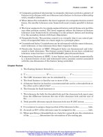
Fig. 20.
Effect
of
canister volume
on
three-day test sequence
6.2
Purge
volume
efects
The comparison made in Section 6.1 demonstrates the important effect the amount
of purge has on the performance of the carbon canister in terms of limiting the
amount of HC release. This effect is also shown in the data presented in Fig. 21.
In
th~s
example, the vehicle has been subjected to the same test cycle sequence as
before, but in this case
two
different levels of purging are examined. Also, a
two
liter canister is used on the vehicle for the testing at both purge levels,
in
order to
see the effect of purge level
on
a single canister volume.
The
two
purge levels used in this example are 150 BV
(300
liters), and a hgher
level of
200
BV
(400
liters). As shown
in
Fig. 21, the higher purge volume
eliminates the increase
in
the amount of HC adsorbed during the
run
loss portion
of the test, and, as a result, allows the overall loading of the carbon bed to be
significantly lowered before the
start
of the diurnal sequence.
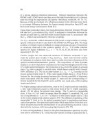
This
effect
is
critical,
as is shown in the amount
of
HC released during the test cycle. At the 150 BV
purge level, the HC release
on
Day
3,
2.12
grams,
is above the allowable 2.0 gram
level, while there are no HC emissions from the 200 BV purge
run
that are above
261
the allowable levels.
Thus,
the higher purge volume allows the vehicle to perform
as required with the
two
liter canister, and
no
additional carbon canister volume is
needed to meet acceptable
HC
emission levels.
fuel
gystemvapor
-
mass
distribution
dong
catbonbed
21.
Effect
of
purge
volume
on
three-day test sequence
6.3
Return
vs.
return-less&el
systems
A
key
parameter in the generation of fuel vapor
is
the temperature level reached in
the fuel tank during vehicle operation.
As
the temperature approaches the top of
the fuel distillation me, a sizable increase in vapor generation will occur, which
severely impacts the amount
of
HC
vapor that the carbon canister system must
handle. Limiting the temperature increase in the fuel tank
is
an important
parameter affecting the ability
of
the evaporative emission system to maintam
allowable emission levels.
One method being studied to help in the limiting
of
fuel tank temperatures
is
the
use
of
a returnless fuel system.
As
presented in Section 3.1, the return-less fuel
262
system eliminates the return
of
the high temperature fuel from the engine to the fuel
tank, which reduces the overall fuel temperature in the
tank.
The effect
of
this
temperature reduction will be examined, again with the example vehicle and test
sequence.
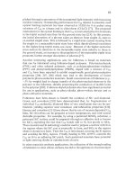
The example vehicle has been
run
through the test sequence using a
two
liter
carbon canister and a
150
BV
purge level. Fig.
22
presents the results for both a
return and return-less fuel system used
in
the vehicle.
As
shown, the fuel vapor
temperature and the amount
of
fuel vapor generated are both lower for the return-
less system. This reduces the amount
of
HC
adsorption required
in
the carbon
canister, and it also reduces the amount
of
HC
emissions
in
the test sequence. The
return fuel system used with the stated purge volume and canister size emits an
unacceptable level of HC during one
of
the diurnal sequences
(2.12
grams), while
the return-less system emission values are well below the acceptable level.
&I
system vapor
generated
600
500
400
300
200
IO0
0
avlm
mm-c~m
test
procedure
point
czd
5:
3n
can
HC
released
5-om
carbon
bed
s
2
‘tL
E
8
v
test
procedure
point
Fig.
22.
Effect
of
fuel return
vs.
Returnless on three
fuel
vapor
temperature
-day
test sequence
263
7
Application
of
Canisters in
ORVR
Control
Tests of numerous fuel tanks under
EPA
refueling test conditions, as outlined
in
Fig.
1,
indicate that most of the fuel vapor generation rates during the refueling
event are
in
a range of 1.25 to 2.0 grams per liter (5 to
8
grams per gallon) of fuel
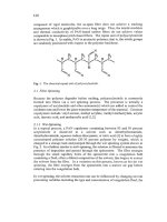
dispensed [28,37,38]. Fig. 23 shows the rate of fuel vapor generation during
refueling as a function of fuel dispensing rate and temperature for the fuel tad
from the example vehicle presented in Section
6.
It should be noted that systems
with different fuel filler pipe and fuel tank geometries
may
show different effects
over the dispensing rate range.
7.1
Loading
of
OR
VR
fuel
vapors
The values shown in Fig. 23 inlcate that the
ORVR
fuel vapor flow rate, based on
vapor generation rate and fuel hspensing rate, can vary from
20
g/min
to above
50
g/lmin
at high temperature and flow conditions.
To
compare the HC adsorption at
these rates to the low
40
g/hr
flow rate shown
in
Fig. 9, the 50
g/min
n-butane load
of
the one liter canister
is
presented
in
Fig. 24. Comparison of the curves
in
the
two
Figs. shows the large difference
in
time till break through for the
two
inlet
flow
rates
(100
minutes vs.
1
.Q
minutes). It is also interesting to note the difference
in
the amount
of
HC
adsorbed by the one liter of activated carbon at the point of break
through (71 grams vs. 48
grams).
‘Ih
result, a
32%
adsorption capacity reduction,
agrees with the effect of
HC
loading rate that was discussed
in
Section 5.2.2.
rnl
rate
(LPM)
Fig.
23.
Fuel tank
HC
vapor
generation
rates
as a
function
of
fill
rate
and
temperature
0
0
.1
.3
.5
.7
.9
1.1
1.3
time
(min)
Fig.
24.
Loading
and breakthrough
curves
in a
one-liter canister,
50
g/mm
N-butane
feed
rate
264
7.2
OR
VR
applications
As
shown in previously in Fig. 1, the
EPA
refueling test
has
the same initial
steps
as the three day
diurnal
test, including a
40%
initial fuel
tank
fill, a saturated carbon
canister, an initial cold and hot engine drive sequence, and a running loss dnve
cycle. At
this
point in the refueling test, the fuel
tank
is drained and refilled to 10%
of its capacity. Following
a
vehicle
soak
to
stabilize the fuel system temperature,
the actual refueling of the vehicle is performed. The test requires that at least
85%
of the tank capacity be dispensed during the test, within a
flow
rate range of 16
Vmin
to
40
Urnin
(4
gallons per minute to 10 gallons per minute).
As
stated
in
Section 1.3, it
is
required that not more than
0.05
grams of hydrocarbons per liter
of dispensed fuel
(0.2
grams per gallon) be released from the vehicle during the
refueling.
Using a fie1 vapor generation rate of 1.25 grams per liter of dispensed fuel
(5.0
grams per gallon),
an
ORVR
test of the example vehicle presented in Section
6
can
be performed. The amount of fuel dispensed for this vehicle will be
60
liters
(1
5
gallons),and the limit for
HC
release becomes
3.0
grams. In this test, the vehicle
has been subjected to the steps in the test procedure preceding the refueling event
using a
200
BV
purge. Thus, at the end
of
the vehicle
soak,
the canister
has
an
HC
loading of
53
grams, which then becomes the condition of the canister at the start
of the refueling. The resulting canister loading and breakthrough curves for the
ORVR test performed at 16
Vmin
and
40
Ymin
is shown in Fig.
25.
Both refueling
tests show that the
two
liter carbon canister gained about
73
grams, and released
about 1.4 grams of
HC,
which is well below the allowable level of 3
.O
grams.
Fig.
25.
Hydrocarbon
adsorption
and
release
as
a
function
of
ORVR
fill
rate
The effect
of
the vapor generation rate during
ORVR
testing is demonstrated in Fig.
26,
where the effect of an increase in vapor generation rate from
1.25
g/1
to 1.375
gA(5.0
to
5.5
grams per gallon) is presented. The amount of
HC
adsorbed in the
265
canister is about the same for the
two
cases, but the additional vapor generated at
the higher rate caused an
HC
release
of
almost
8
grams which is well above the
allowed
3.0
gram
value.
This
result shows the importance
of
fuel vapor generation
rate
on
the design
of
an emission control system.
'0
0.3
0.6
0.9
1.2
1.5
8
4
4
2
0
0
0.2
0.4
0.6
0.8
1
12
1.4
1.6
time
(min)
tinli?
{mill)
Fig.
26.
Hydrocarbon
adsorption
and
release
as
a
function
of
ORVR
vapor
generation rate
8
Summary and Conclusions
The role of activated carbon in the control of automotive evaporative emissions
is
summarized below:
Automotive evaporative emissions have been identified as a source of
HC
compounds that can contribute to smog pollution.
Both the
EPA
and
CARE!
have established regulations which define the levels
of evaporative emissions that can be tolerated.
These agencies have developed specific test procedures which
must
be used
to
verify compliance with the established limits.
The current requirements have led to the development
of
pellet shaped
activated carbon products specifically for automotive applications. These
pellets are typically generated as chemically activated, wood-based carbons.
The adsorption
of
hydrocarbons by activated carbon
is
characterized by the
development
of
adsorption isotherms, adsorption mass and energy balances,
and dynamic adsorption zone
flow
through a fixed bed.
The design
of
activated carbon canisters for evaporative emission control
is
266
affected by characteristics
of
the carbon itself, by physicaYgeometrica1 design
options, and by the final working environment of the canister.
A
vehicle fuel vapor control system must be designed to meet both driving and
refueling emission level requirements. Due to the nature
of
hydrocarbon
adsorption, this emission control
is
a continuous operation.
The key sources of evaporative emissions during drive cycles are
running
loss
emissions, hot soak emissions, and diurnal emissions.
Design concerns for drive cycle emission control include canister volume
requirements, purge volume effects, and the use
of
return vs. returnless
fuel
systems.
The rate
of
vapor generation during refueling is a major parameter affecting
the design of carbon canisters
to
meet
ORVR
requirements.
The reduced adsorption capacity at
ORVR
vapor generation rates requires
increased efficiency in the canister design,
in
order to limit the effect on cost
and performance
of
the evaporative control system.
9
References
1.
2.
3.
4.
5
6
7.
8.
9.
10.
US.
Environmental Protection Agency,
Fact Sheet
OMS-12,
January,
1993.
P. J.
Lioy,
Human Exposure Assessment for Airborne Pollutants,
National Academy
Press, Washington,
D.C.(1991).
State
of
California Air Resource Board,
California Fuel Evaporative Emissions
Standard and Test Procedure for
!970
Model Light Duty Vehicles,
April
16, 1968.
P. Degobert,
Automobiles and Pollution,
Society
of
Automotive Engineers,
USA(
1995).
U.S.
House
of Representatives,
Clean Air Act of
1990,
Conference Report,
Section
232,
pp.
137.
General
Motors, Environmental
Activities
Staff,
Mobile Emission Standards Pocket
Reference,
March,
1990.
S.W.
Martens
and
K.W.
Thurston,
Society of Automotive Engineers Paper Number
680125,
1968.
US.
Code
of
Federal Regulations,
Control ofAir Pollution From New Motor Vehicles
and New Motor Vehicle Engines; Certtfication and Test Procedures,
Title
40,
Part
86.
US.
Environmental
Protection
Agency, Final Rule,
Control of Air Pollution From New
Motor Vehicles and New Motor Vehicle Engines; Evaporative Emission Regulation for
Gasoline
and
Methanol
-
Fueled Light-Duty Vehicles, Light-Duty Trucks and Heavy-
Duty Vehicles,
Federal Register,
Vol.
58,
No.
55,
March
24,
1993.
U.S.
Environmental Protection Agency, Final Rule,
Control ofAir Pollution From
New
Motor Vehicles and
New
Motor Vehicle Engines; Refueling
Emission
Regulations for
267
Light-Duty Vehicles and Light -Duty Trucks,
Federal Register, Vol. 59, No. 66, April
6, 1994.
1
1.
Kirk-Othmer Encyclopedia of Chemical Technology,
4th Edition, Volume 4, John
Wiley
&
Sons, New York( 1992).
12.
Carmbba, R.V., et.al.,
Perspectives ofActivated Carbon
-
Past, Present and Future,
AICHE Symposium Series No. 233, Vol.
80,
pp. 76-83.
13.
T.Wigmans,
Carbon,
27,
13(1989).
14. H. Juntgen,
Carbon,
15,273(1977).
15. R.A. Hutchins,
Chem Eng.,
87:2,
lOl(1980).
16. P.N. Cheremisinoff and F. Ellerbusch
(Eds),
Carbon Adsorption Handbook,
Ann
Arbor
Science Publications, Inc.( 1978).
17. M.W. Leiferman and S.W. Martens,
Society ofAutomotive Engineers Paper Number
830630, 1983.
18.
T.L. Darlington L. Platte, and C. Shih,
Society ofAutomotive Engineers Paper Number
860529, 1986.
1
9. Westvaco Special Report,
Nuchar Activated Carbons for Automotive Hydrocarbon
Emission Control,
Westvaco Corporation, 1986.
20. J.E. Urbanic,
E.S.
Oswald, N.J. Wagner, and H.E. Moore,
Society of Automotive
Engineers Paper Number
890621, 1989.
21. H.M. Haskew and W.R. Cadman,
Society of Automotive Engineers Paper Number
891121, 1989.
22. H M. Haskew, W.R. Cadman, and
T.F.
Liberty,
Society ofAutomotive Engineers Paper
Number
901
1
IO,
1990.
23. C.H. Schleyer and W.J. Koehl,
Society of Automotive Engineers Paper Number
861552, 1986.
24. R.L. Furey and
B.E.
Nagel,
Society of Automotive Engineers Paper Number
860086,
1986.
25. P. Girling,
Automotive Handbook,
Robert Bently, Publishers, Cambridge, MA( 1993).
26. J. Heinemann and
B.
Gesenhues,
Society of Automotive Engineers Paper Number
930858,1993.
27. W.J. Koehl, D.W. Lloyd, and L.J. McCabe,
Society ofAutomotive Engineers Paper
Number
861551,1986.
28.
G.S. Musser and H.F. Shannon,
Society of Automotive Engineers Paper Number
861560, 1986.
29. R.H. Perry, D.W. Green, and
J.O.
Maloney (Eds),
Chemical Engineer's Handbook,
Sixth Edition, McGraw-Hill, New York( 1984).
30.
J.H. Harwell, A.I. Liapis,
R.
Litchfield, and D.T. Hanson,
Chem
Engng. Sci.
35,
2287( 1980).
3
1.
K.S.
Hwang, J.H. Jun, and W.K. Lee,
Chem. Engng. Sci.
50,8
13( 1995).
32. P.N. Cheremisinoff (Ed),
Handbook of Heat and Mass Transfer, Volume
2.
Mass
Transfer and Reactor Design,
Gulf Publishing, Houston( 1986).
33. G. Tironi, G.J. Nebel, and R.L. Williams,
Society of Automotive Engineers Paper
Number
860087,1986.
34. M.M. Dubinin and Radashkevich,
Compt. Rend. Acad Sci. USSR
55(4),
327(1959).
35. H.R. Johnson and R.S. Williams,
Society of Automotive Engineers Paper Number
902119, 1990.
36. M.J.Manos, W.C. Kelly, and M. Samfield,
Society of Automotive Engineers Paper
Number
770621, 1977.
268
37.
J.N.
Braddock,
P.A.
Gabele, and
T.J.
Lemons,
Society
of
Automotive Engineers
Paper Number
861
558,1986.
38.
G.S. Musser,
H.F.
Shannon, and
A.M.
Hochhauser,
Society ofAutomotive Engineers
Paper Number
900155,
1990.
269
CHAPTER
9
Adsorbent Storage for Natural
Gas
Vehicles
T.L. COOK
',
C.
KOMODROMOS
*,
D.F. QUINN
AND
S.
RAGAN
'
Atlanta Gas Light Co., Atlanta, GA
'
British
Gas
plc, Loughborough, England
Royal Milita
y
College
of
Canada, Kingston, Ontario
Sutcliffe Speakrnan Carbons Ltd, Ashton-in-~akersfield, England
1
Introduction.
1.
I
Natural Gas Vehicles.
With air quality issues gaining prominence around the world, the use of natural
gas as a vehicular fuel has become a more attractive alternative
to
gasoline and
diesel fuels because of its inherent clean burning charactenstics. Natural gas
vehicles (NGVs) have the potential to lower polluting emissions, especially
an
urban areas, where air quality has become a major public health concern. The
most important environmental benefit of using natural gas is lower ozone levels
in urban areas because
of
lower reactive hydrocarbon emissions. NGVs also
have lower emission levels of oxides
of
nitrogen and sulfur,
known
to cause
"acid rain". Estimates of the greenhouse impact by NGVs vary widely, but it
is
generally agreed that the global warming potential of an NGV will be less than
that of a liquid hydrocarbon-fuelled vehicle
[
11.
In
the United States, in particular, recent legislation has mandated sweeping
improvements to urban air quality by hiting mobile source emissions and by
promoting cleaner fuels. The new laws require commercial and government
fleets to purchase a substantial number of vehicles powered by an alternative
fuel, such as natural gas, propane, electricity, methanol or ethanol. However,
natural gas is usually preferred because of its lower cost and lower emissions
compared with the other available alternative gas or liquid fuels. Even when
Compared with electricity, it has been shown that the full fuel cycle emissions,
including those from production, conversion, and transportation
of
the fuel, are
lower for an NGV
[2].
Natural gas vehicles offer other advantages as well.
Where natural gas is abundantly available as a domestic resource, increased use
270
of NGVs would limit dependence on foreign produced oil and petroleum
products.
The environmental and energy security advantages offered by natural gas
vehicles are important, but NGVs must be competitive on an economic basis in
order to be successful in the market. Currently, the commodity and distribution
costs for natural gas are lower than those of gasoline and diesel. The natural gas
industry is able to take advantage of its substantial investment in a gas pipeline
and distribution network put in service for other markets. As a result, an NGV
refueling station can be installed at almost any location where natural gas
service
is
available, with the incremental investment for the NGV fuel
distribution network being only the station equipment. However, compared
with gasoline and diesel vehicles, NGVs are currently at a disadvantage because
of high vehicle costs. Gasoline and diesel vehicles benefit from decades of
optimization and high volume manufacturing. At the moment NGVs are simply
gasoline vehicles converted to operate on natural gas. As a result, the fuel
storage system geometry and placement are not optimized for natural gas.
A significant problem arises because natural gas at normal temperature and
pressures has a low energy density relative to solids or liquids, making it
difficult to store adequate amounts on a vehicle. Despite this, NGVs can
compete with conventional vehicle types because of the lower fuel cost,
especially in high fuel use markets. Because of the perceived advantages of
NGVs the development of improved, lower cost, natural gas fueling and storage
systems has been ongoing for several years.
The history of natural gas vehicles dates back to the 1930s when Italy launched
an NGV program. operating NGVs. The
continued popularity
of
NGVs in Italy is mainly due to the price of natural gas,
which is less than one thd that of gasoline. More than 340,000 vehicles
operate
on
natural gas in Argentina, the largest number of any country, even
though NGVs were introduced as recently as 1984. Countries of the former
Soviet Union operate more than 200,000 NGVs and other notable programs
exist in New Zealand, Canada and the United States, each of which
has
tens of
thousands of NGVs operating on their roads [3].
When NGV programs are initially launched, a refueling infrastructure usually
does not exist to support these vehicles. To accommodate this limitation, most
NGVs have been bifuel vehicles. The vehicle is operated primarily on natural
gas and then switched over to gasoline after the natural gas is depleted. With
this scenario, the vehicle operator does not have to be concerned with locating a
natural gas refueling station immediately when the level of natural gas stored
on
board gets low. The drawbacks of the bifuel NGV include reduced cargo
volume on the vehicle, since two fuel storage systems are onboard, and lower
performance of the vehicle, since its engine is optimized for gasoline. A new
Today, Italy has over 290,000
27
1
bifuel concept that has emerged is to optimize the vehicle to
m
on natural gas,
but provide a "limp home" capability on gasoline with a small pony tank. Ths
approach is in response to market fears of running out of fuel if the vehicle is
a
dedicated, or single fuel, natural gas vehcle.
The factory-produced, dedicated NGV is the ultimate goal of the NGV industry
because it will reduce the incremental cost of the vehicle, the fuel system will be
better integrated into the vehicle, and the vehicle performance can be optimized
for natural gas. A dedicated NGV's emissions, power, and driveability can be
superior to a comparable gasoline vehicle. There is however, a reluctance by
some automobile manufacturers to produce dedicated NGVs until the refueling
infrasfxucture
is
more fully developed.
1.2
Energy
Aspects
of
NGVs.
Although natural gas, which is mostly methane, has a higher hydrogen to carbon
ratio than other fuels and consequently a greater energy per unit mass,
it
cannot
be stored to the same density as these fuels. Even when liquefied at its normal
boiling point of
-161
OC, the energy density (defined as the heat of combustion
per unit volume) is only 23
MJ
per liter, considerably lower than that of diesel
or gasoline with approximately 37 and 32 MJ per liter respectively. Compressed
natural gas (CNG) at 20 MPa
(200
bar) and ambient temperature (25°C) has an
energy density of
<
10
MJ
per liter. In these condhons, about 230 unit volumes
of natural gas at
0.1
MPa
(1
bar) are compressed to one unit volume of storage
container, often designated as 230 VN (an ideal gas would be 200 V/V). For
the same driving range a CNG vehicle using these pressures, requires a storage
vessel at least three times the volume of a gasoline tank. With limited space on
board a vehicle, this can present some challenges. The use
of
even higher
pressures for greater energy density has been suggested. It should also be noted
that at these pressures, a cylindncal conformation for the vessel is required.
The use of adsorbent materials, such as active carbons, porous silicas and porous
polymers,
in
a storage vessel for storing natural gas at lower pressures,
known
as adsorbed natural gas, ANG, is another alternative attempting to make NGVs
more cost effective when competing with other vehicle types. In AN6
technology, natural gas is stored at relatively low pressures, 3.5
to 4.0 MPa (35
to
40
bar)
through the use of an adsorbent. Much work has been directed
towards the adsorbent, however, for ANG to be successful for vehicular use
in
contrast to high pressure
(20+
MPa) CNG, a complete storage system must be
considered. This storage system must address every aspect, both the advantages
and disadvantages, of adsorption. This chapter attempts to review the
characteristic properties of the adsorbent which are best suited to methane
storage at temperatures substantially above its critical temperature
(191
K) as
well as the fuel, natural gas, with its other non-methane constituents which
272
affect adsorption storage. Additionally consideration is given to the storage
vessel design
so
that the heat effects which occur during filling and discharge
can be minimized and also to the shape of the vessel
so
that it best utilizes the
space available on board the vehicle. Collectively these factors contribute to the
overall performance of an ANG storage system.
Flat
Storage
Tank
Fig.
1.
A
basic layout
for
a
vehicular
ANG
storage system.
A simplified diagram of an ANG storage system is shown in Fig.
1.
On filling
the natural gas is passed through a small carbon bed which is necessary to
remove by adsorption the small amounts of the
C,
+
hydrocarbons present in the
natural gas before it enters the main storage vessel. If this is not done then a
reduction in overall capacity results on repeated fill-empty usage. While
discharging the gas from the storage vessel it is passed back through the
protective guard bed. The bed
is
heated to aid desorption of these higher
hydrocarbons back into the gas stream which is fuelling the engine.
The generalized statement can be made that the energy density in a vessel filled
with adsorbent will be greater than that of the same vessel without adsorbent
when filled to the same pressure. The extent to which the above is true depends
on many factors and considerations which are discussed more fully later.
Compression of CNG to
20
MPa requires four stage compression. Provision of
such facilities is costly, and it is an energy consuming process. There is also a
substantial heat of compression which results
in
a temperature rise of the
compressed gas.
This
means that in practice less than
230
VN
are stored when
a CNG vessel is filled to
20
MPa unless the filling process is carried out
isothermally.
For simplicity and reduced cost, an adsorption storage system using single stage
compression is attractive, which puts a practical upper limit to the adsorption
273
pressure of about
5
MPa. This is not a serious constraint fiom consideration of
the adsorption process, since at
5
MPa many adsorbents have reached their
isotherm plateau, although a few still exhibit some increase in uptake beyond
this pressure. Therefore, to be equivalent to a CNG system at
20
MPa, it is
necessary to store as ANG the same amount of natural gas but at one quarter or
less of this pressure. For some years now a benchmark pressure of
3.5
MPa has
been somewhat arbitrarily adopted for the comparison
of
different adsorbents.
This pressure is only one sixth that in use for CNG vehicles in many countries.
Although the requirements for a NGV storage system are demanding, more than
a million CNG vehcles and about one thousand LNG trucks or buses are in use
worldwide, only a handful are
known
to operate on ANG. The Atlanta Gas
Light Adsorbent Research Group, (AGLARG), a consortium of oil and gas
utility companies and Sutcliffe Speakman, a carbon manufacturer, has been at
the forefront of advancing ANG technology for vehicles, by developing
adsorbents of high storage performance for natural gas, coupled with the design
of novel tank containers for better integration into the vehicle. Additionally,
as
discussed
in
section
5
of
this
chapter, they have developed guard beds for the
protection of the storage carbon. Also, there are some opportunities for ANG
which are less stringent. Examples of possible use may be in small limited
range vehcles such as delivery trucks, golf carts, fork lift trucks and garden
tractors or lawnmowers. No natural gas storage system will come close in
energy density to diesel or gasoline, but, with the emission concerns raised
earlier, it can contribute to improved air quality. Moreover, for some parts of
the world it can provide a useful domestic vehicular fuel.
1.3
Natural
Gas
as
a
Fuel.
The characteristics of natural gas make it an ideal fuel for spark-ignition
engines. Methane, the principal component of natural gas,
is
a clean burning
fuel because of its hgher hydrogen to carbon ratio than other hydrocarbon fuels.
Natural gas also has a higher research octane number, (RON), around
130,
compared to
87
for regular unleaded gasoline, which allows the use of higher
compression ratio engines, with better performance and fuel efficiency. The
combustion of natural gas results in less ash and particulate matter in the engine
cylinders, compared with petroleum based liquid fuels. Over time, the ash and
particulate contaminate the lubricating oil causing abrasion and wear and also
foul the spark plugs. Therefore,
from
a maintenance perspective, natural gas
engines require fewer oil and spark plug changes.
With dedicated vehicles, the engine can be optimized for the attributes of natural
gas.
In bifuel, or converted NGVs, the engine is usually not modified
significantly from its original gasoline configuration. For a bifuel NGV, a fuel
pressure regulator, an airifuel mixer, and an electronic engine controller must be
added to the velncle in conjunction with the CNG or ANG storage cylinders.
The state-of-the-art NGV conversion kit now contains a fully electronic, closed-
loop engine controller that provides much improved performance over the open
loop mechanical systems of the past. The air/fuel mixer is mounted
on
the
intake manifold to deliver a mixture of air and natural gas to the engine‘s
cylinders, much like the gasoline carburetor. However, most factory produced,
dedicated NGVs will use fuel injection, either single point (throttle body) or
multiple point (at each engine cylinder), for more precise fuel control and to
obtain better economy, performance and lower emissions.
2
Storage
of
Natural Gas.
2.1
Methods
of
Natural Gas Storage
Historically, there have been
two
options for storing natural gas on a vehicle: as
compressed gas or in a liquefied state. As stated in the previous section, the
energy density of CNG as a fuel is less than that
of
gasoline. Hence vehicles
helled by CNG exhibit a reduced driving range, unless a higher percentage of
the volume within a vehicle is used for fuel storage.
Liquefied natural gas (LNG) vehcles have a higher energy density, but handling
of this cryogenic liquid (-162°C) poses some safety concerns. LNG can also
present an operational problem if the vehcle
is
not operated frequently. The
liquid slowly vaporizes, pressurizing the storage vessel which must then be
vented to the atmosphere if the vehicle does not use enough fuel to keep this
“boil-off‘ in check. The storage cylinders for CNG and the super-insulated
LNG tank add significantly to the incremental cost of a NGV, and therefore
current NGVs have a cost premium of several thousand dollars over their
gasolme or &esel counterparts.
Several alternative methods have been considered in order to increase the
energy density of natural gas and facilitate its use as a road vehicle fuel. It can
be dissolved in organic solvents, contained in
a
molecular cage (clathrate), and
it may be adsorbed in a porous medium. The use of solvents has been tested
experimentally but there has been little improvement
so
far over the methane
density obtained by simple compression. Clathrates of methane and water,
(methane hydrates) have been widely investigated but seem to offer little
advantage over ANG
[4].
Theoretical comparison of these storage techniques
has been made by Dignam
[5].
In
practical terms, ANG has shown the most
promise
so
far of these three alternatives to CNG and LNG.
For many classes of vehicles, the use of CNG storage is a compromise between
volume of gas required to provide an acceptable range dictated by the internal
275
volume of the storage cylinder, the amount of space available within the vehicle
for the cylinder installation, (the external cylinder envelope), and the weight of
the storage system. Thus for large vehicles such as transit buses and heavy duty
trucks, the emphasis is on reducing the weight of the storage system, while on
passenger vehicles, although weight is still important, another concern is the
intrusion of the cylindrical storage system on the passenger and load space of
the vehicle.
On-board storage at much lower pressures through the use of adsorbents would
bring about important benefits by allowing the use of lighter tanks that could be
made to conform to otherwise unused spaces within a road-going vehicle. The
realization of this advantage, and those discussed above, depends on a detailed
understanding of the ANG adsorbent properties and behavior.
2.2
On-board Storage Comparisons
The relative volume and mass for the different fuel systems, normalized to that
of diesel, is shown in Fig.
2
and illustrates the disadvantages
of
most of the
alternative fuels compared to gasoline and diesel, in terms of storage density.
_
-
0
20
40
60
80
100
Relative Weight
/
Volume
/
Diesel
Gasoline
ANG
CNG
LNG
Methanol
\
HY-
Eiectriclty
Fig.
2.
Relative
volume
and
mass of
different
fuel
systems normalized
to
diesel fuel
in
terms
of
storage density.
For natural gas, LNG begins to approach the energy density
of
the conventional
liquid fuels and provides a goal for other natural gas storage methods. In
contrast, CNG and ANG require substantially greater storage volume compared
to diesel and gasoline. Additionally, there is a weight penalty due to the
containers. For CNG the weighvliter capacity of current steel tanks is
0.9-1.2
kg/liter but
0.4
kglliter can be achieved using composite tanks. Although ANG
tanks may be lighter than steel CNG cylinders, this advantage is offset by the
276
weight of the adsorbent. The relative volumes used
in
Fig.
2
for both LNG and
CNG are based on internal vessel volume and not the effective external volume,
the use of which would lower the energy density.
2.3
ANG
Storage
for
Vehicles
Early trials of vehicle applications of ANG showed that useful on-board storage
volumes could be achieved at
3.5
MPa, but the carbons used tended to be highly
activated ones
in
a granular form, having large surface area but with a
consequent low packing density, leading to high void volume in the tank
[6].
It
was recognized that the use
of
monolithic carbons would lead to improvements
in
the performance of ANG storage systems. Developments by AGLARG,
discussed later in this chapter, using carbon monoliths that can be shaped to
completely fill a vessel, coupled with the use of space saving flat tanks, means
that ANG storage can be used on vehicles much more effectively than before
~71.
25
i700
__
-
-10
4
to
0
10
20
30
40
Distance
travelled (miles)
++
Temperature
+=
Flow
+
PreSSwd
i
-
Fig.
3.
Tank
pressure,
gas
flow
and adsorbent bed temperature
of
the
ANG
storage
system
on
the Vauxhall Cavalier
at
100
kmih.
AGLARG members have operated several ANG vehicles. For example, a
Chevrolet pick-up truck, operated by Atlanta Gas Light Co. used a pelletized
form of the Anderson AX-21 carbon.
Another vehicle, a Vauxhall Cavalier
estate car (station wagon), operated by British Gas, used a high performance
coconut shell granular carbon developed by Sutcliffe Speakman. In this vehicle,
the carbon was stored as granules
in
a composite tank supplied by
HM
International. These vehicles were fully instrumented, allowing gas flow and
temperature measurement during on the road performance. Fig.
3
shows how
the tank pressure, gas flow and carbon bed temperature of the fuel system varied
during a particular run at
60
m.p.h.
(100
km/h).
Since desorption is an
277
endothermic process, heat must be supplied from some external source if the
adsorbent is to remain at ambient temperature. A reduction in temperature
would result in more gas being retained by the adsorbent and so less is available
as fuel for the vehicle.
In
this relatively large and well insulated container, the
temperature decreased steadily as the trial proceeded, until after
35
miles (56
km),
the temperature had fallen to
-5OC
and the tank pressure
to
0.64 MPa, (6.4
bar). The gas flow rate under these conditions was insufficient to maintain the
road speed and the test was stopped. When the tank returned to ambient
temperature the pressure rose to
1.45
MPa, (14.5 bar). Comparisons with the
isotherm for the carbon used, suggests that only about half the gas stored
on
the
carbon had been consumed and that the potential range had not been approached
because of the fall
in
adsorbent temperature.
The vehicle was subsequently modified to test a developmental batch of active
carbon in the form of briquettes. The complete storage system was removed
and replaced by an array of
18
cm diameter stainless steel cylinders, in which
the briquettes in the form of
16
cm diameter disks were loaded. The briquettes
were not a matched fit within the cylinders because stainless steel tube of the
correct diameter was unavailable. This resulted in an annular space between the
briquettes and the cylinder wall. Three
of
the filled cylinders were positioned
in
a cradle
on
the vehicle floor, and two other cylmders were mounted directly
beneath the cradle under the vehcle floor. In this configuration the
performance of the vehicle improved, although there was still a marked decrease
in temperature during operation. The annular gap around the carbon briquettes
was not ideal for promoting heat transfer. Nevertheless, the tests showed that
improvements were possible by using immobilized, rather than granular carbon,
[8].
These results reinforce the fact that the behavior of an ANG storage tank is
governed by heat and mass transfer effects in the adsorbent. The heat
of
adsorption of methane on carbon, ca.
16
Jdlmole, is also sufficient to cause
considerable temperature variations during filling. The effect on ANG is
a
reduction in potential storage as the temperature increases during filling. The
extent of temperature rise is dependent on the adsorption capacity of the carbon,
the heat transfer of the system to the surroundings, and
on the filling time.
There
is
also
a
temperature increase during filling of CNG storage systems that
reduces the amount of gas dispensed to the storage cylinder, but this
is
less
significant than for ANG.
2.4
ANG
Storage
Vessels
The characteristics of ANG storage described above suggest a new approach to
the design of adsorbent and tanks, including:
278
monolithic adsorbents occupying all the available volume of the tank
with minimum void volume and with improved thermal conductivity to
maximize adsorption capacity
careful packing of the carbon within the tank to encourage heat transfer
tanks with a high surface to volume ratio for better heat exchange with
the surroundings
development of shaped vessels which can be "conformable" with the
vehicle shape and designed to maximize storage volume and reduce the
spatial intrusion within a vehicle.
To meet these requirements, radically new types of fuel containers are needed
to exploit fully the unique features of ANG storage, and maximize the on-board
storage capability. Thus the use of immobilized carbons,
in
the form
of
briquettes which are shaped to match the geometry
of
the tank, is an important
element, since this minimizes void volume within the container.
In
addition,
this can help to reduce thermal grahents throughout the tank, since the thermal
conductivity of immobilized carbons has been measured to be around
65%
greater than that of corresponding loose particles, thus increasing the heat
transfer. The much lower operating pressure of ANG compared to CNG permits
non-cylindrical tank designs that can meet the above requirements and are able
to be better integrated within vehicle structures, minimizing the impact on the
vehicle and improving weight distribution. With
CNG
storage, cylindrical or
spherical geometry vessels are almost mandatory, due to the very high pressures
and the resulting hoop stresses generated within the vessel. However, spheres
and cylinders are not amenable to efficient packaging within a modem vehicle
and there is wasted space around the spherical or cyhdrical vessel, (the
parasitic volume), when it is fitted to a vehicle. Thus a nearly thirty percent
increase in storage volume could be realized by having a rectangular rather than
a circular cross section.
In principle, the lower pressures used in ANG can lead to lighter, thinner walled
tanks. However, in ANG the weight
of
the adsorbent increases the weight of the
storage system. A number of conceptual containers have been investigated,
including completely flat section
tanks.
However to date, most effort has been
directed at obtaining multi-cellular aluminium alloy tanks which are essentially
rectangular but have cells with curved external walls to minimize stresses at
these points. This is illustrated in Fig. 4
[9].
These tanks are manufactured by a
single step extrusion process to form a multi-cell body, followed by carefid
welding of individual end caps to seal the tank.
279
(Assembly)
Fig.
4.
specifically
for
ANG
applications.
Schematic
of
aluminum alloy extruded storage vessel developed by
AGLARG
2.5
Safety
Safety is essential for all pressure vessels, but ideally NGV containers should
also be lightweight and inexpensive, with the highest possible capacity for a
specified external envelope. In a given application, some degree of compromise
is unavoidable between these conflicting requirements.
The prevalence of CNG storage can be attributed to the established use of high
pressure steel cylinders for transporting industrial gases, for which there are
long established safety standards for construction and use. However, when
using pressure vessels as fuel tanks for vehicles, new safety issues arise that
have to be carefully considered. Although steel cylinders are the most widely
used for CNG vehicle applications, today there is a broad range of cylinder
types available, with increasing interest in lightweight composite cylinders.
NGV cylinders are characterized by three ratios, weighdcapacity,
capacity/external volume and costlcapacity
[IO].
At one extreme, steel cylinders
are relatively inexpensive and reasonably space efficient but heavy, whilst at the
other extreme, carbon fiber composite cylinders are relatively light but very
expensive and bulky. The cost of fully wrapped carbon fiber cylinders is three
to four times the cost of a steel cylinder having the same capacity.
A major issue with NGV cylinders has been the lack of a world-wide standard
for their manufacture, inspection and testing. Some national standards, such as
the New Zealand standard NZS
5454
and the
US
ANSIlAGAlNGV2 standards
have been adopted by other countries. Currently,
IS0
are working to produce an
internationally accepted standard for NGV cylinders.
There are currently no standards or regulations governing
ANG
containers. The
existing regulations for CNG cylinders are not appropriate, particularly if non-
cylindrical designs
are
being considered.
Thus
the use of ANG tanks requires a
comprehensive design and evaluation program to ensure safety. Applying
standard pressure vessel codes, such as ASME
VIII,
invariably leads to a heavy
and
unnecessarily bulky container. However, in the absence of specific codes,
ANG
tanks that are to be used on public roads must be designed as closely
as
possible to an existing pressure vessel standard. The design must be checked by
finite element analysis, and the design validated by carrying out a program
of
pressure testing on sample tanks to establish burst safety factors and the fatigue
life.
This
approach allows the design engineer to assess the fitness-for-purpose
of the
tank.
However, it may not be possible to obtain full cerb%ication since
some aspect of the
tank
design may fall outside the ASME VIII Code.
The aluminum multi-cell tank shown in Fig.
4
was designed to a British
Standards Institute
(BSI)
Code for stationary pressure vessels,
BS
5500
to
ensure the materials specifications, design calculations, stress levels, welding
and inspection requirements embodied in the code were incorporated into the
design. Moreover, finite element analysis was used extensively. The single
stage continuous extrusion method used to manufacture the tank body is not
explicitly covered in
BS5500
because the extrusion die requires the aluminium
to separate and recombine as it flows through the die, forming invisible ”seam
welds” along the tank body. Nevertheless, careful manufacturing and quality
control testing yielded extrusions with very high material strength. Following
the development of
this
type of tank, an addendum to the
BSI
Code, which
allowed this type
of
extrusion only if the contracting parties agreed on the
quality
and
integrity of the extrusion, was issued.
3
Adsorbents.
3.1
Pe
fonnance
Requirements
One study suggested that a viable ANG system would have to store “12
lb.
of
natural gas per cubic foot of storage” (192 kg/m3), equivalent to about 270 VN
[
1 11. However, this capacity could not be reached with any adsorbent available
at that time. The concept
of
ANG has continued to be attractive and several
studies of adsorbents were carried out in the 1980s, see for example [12-161. In
the early 1990s, the
US
Department
of
Energy (USDOE) set a target figure of
150
VN
deliverable for
an
operational ANG vehicle system working at a
pressure of
3.5
MPa
(35
Bar) and
25°C
[17]. This value was considered
demanding, but realistic and achievable. Values in excess
of
200
ViV have
been claimed for laboratory scale samples, but these have not been
independently validated.
Sometimes storage or delivered quantities have been
2s
1
estimated by extrapolation of experimental values. It is important to distinguish
clearly between an experimentally obtained value and a calculated one which
assumes a parameter, such as a packed density, to obtain a stored or delivered
value. These calculated quantities may not be practically achievable but have
some merit
in
guiding researchers towards a possible goal.
3.2
Principles
ofANG
Development
Enhancement of gas storage capacity through adsorption occurs when the
overall storage density is increased above that of the normal gas density at a
given pressure. The adsorbed phase has a greater density than the gas phase
in
equilibrium with it. However, enhancement in a storage system of fixed volume
can only happen if a greater amount of gas
is
adsorbed compared to the volume
of gas dmplaced by the adsorbent volume.
Adsorption of supercritical gases takes place predominantly
in
pores which are
less than four or five molecular diameters in width. As the pore width increases,
the forces responsible €or the adsorption process decrease rapidly such that the
equilibrium adsorption diminishes to that
of
a plane surface. Thus, any pores
with widths greater than
2
nm
(meso- and macropores) are not useful €or
enhancement
of
methane storage, but may be necessary for transport into and
out
of
the adsorbent micropores. To maximize adsorption storage of methane, it
is necessary
to
maximize the fractional volume of the micropores (‘2
nm
pore
wall separation) per unit volume of adsorbent. Macropore volume and void
volume in a storage system (adsorbent packed storage vessel) should be
minimized
[18,
191.
Presently, the most successful adsorbents are microporous carbons, but there is
considerable interest in other possible adsorbents, mainly porous polymers,
silica based xerogels or zeolite type materials. Regardless of the type
of
material, the above principles still apply to achieving a satisfactory storage
capacity. The limiting storage uptake will be directly proportional to the
accessible micropore volume per volume of storage capacity.
The issue of the theoretical maximum storage capacity
has
been the subject of
much debate. Parkyns and
@inn
[20] concluded that for active carbons the
maximum uptake at 3.5 MPa and 298
K
would be 237
VIV.
This was estimated
from
a
large number of experimental methane isotherms measured on different
carbons, and the relationship of these isotherms to the micropore volume of the
corresponding adsorbent. Based
on
Lennard-Jones parameters
[2
11,
Dignum
[5] calculated the maximum methane density in a pore at 298
K
to be
270
mglml. Thus an adsorbent with
0.50
ml of micropore per ml could potentially
adsorb 135 mg methane per
ml,
equivalent to about 205
VIV,
while a micropore
volume of
0.60
dml
might store 243
VIV.
Using sophisticated parallel slit
models and Monte Carlo simulations or density functional theory, Matranga,
Myers and Glandt [22]
and
Tan and Gubbins [23], have concluded that the
maximum methane density
is
223 mg/ml of pore volume. Hence the maximum
storage volume at 298 K is 220
VN,
based on a pore width
of
1.14
nm
[22] or
1.12
nm
[23], which is the pore width where maximum density occurs, and
assuming that a monolithic carbon
of
piece density 0.67 glml having these
properties could be made.
3.3
Pore
Size
Distribution
Although a correlation between
BET
surface areas from 77
K
nitrogen
isotherms and methane uptake at
298
K
and 3.5 MPa has been shown for many
carbon adsorbents, [ll, 201, deviations from this relationshp have been
observed [20]. However, as a primary screening process for possible
carbonaceous adsorbents for natural gas,
this
remains a useful relationship. It
should be noted that
this
correlation only seems to be applicable for active
carb ons
.
The models of Matranga, Myers and Glandt [22] and Tan and Gubbins [23] for
supercritical methane adsorption on carbon using a slit shaped pore have shown
the importance of pore width on adsorbate density.
An
estimate of the pore
width distribution has been recognized
as a valuable tool
in
evaluating
adsorbents. Several methods have been reported for obtaining pore size
distributions, (PSDs), some
of
which are discussed below.
Many years ago, Dacey and Thomas [24] used the direct approach of adsorbing
molecules of different size on the same adsorbent.
This
method has also been
used more recently by Jagiello et al. [25] who adsorbed alkanes of increasing
size supercritically on different carbons. Because of the limited range
of
suitable adsorbate molecules, larger pore dimensions are difficult to determine.
It is also a very time consuming technique. Horvath and Kawazoe [26] used
the subcritical,
77
K, nitrogen isotherm at very low relative pressures to
determine the pore size distributions. Stoeckli [27] has also used subcritical
isotherm analyses based on the Dubinin-Radushkevich
@-R)
equation for the
determination
of
PSDs. Stoeckli’s method [27], however, imposes a Gaussian
distribution to the solution of the pore size distribution. Kakei et al. [28] used
the D-R plot of subcritical isotherms to observe stepwise pore filling, and from
this
obtained a PSD. While all
of
the above methods are useful, the conditions
for adsorbate measurement are quite different to supercritical methane storage
where no condensed or quasi condensed phase exists. For
this
reason, and
because their interest was
in
supercritical methane adsorption,
Sosin
and Quinn
[29] have proposed a method
of
obtaining the PSD for a carbon adsorbent
directly by analysis of the supercritical methane isotherm. They calculated
methane density data for the various pore widths considered
in
the model of Tan
283
and Gubbins
[23].
In using this supercritical model, any problems in the
isotherm analysis due to possible condensation and uncertain adsorbed phase
density are avoided.
No
restrictions are imposed on the solution
of
the PSD.
Sosin and
Quinn’s
approach makes it possible to compare different carbon
adsorbents and gives some indication
of
how close they come to having the
ideal pore width, 1.12
nm,
suggested by the Tan and Gubbins model
[23].
Since
this
model defines the pore width
as
being from the center
of
each carbon atom
forming the pore, the “effective pore width”
of
this ideal pore, as defined by
Everett and Pow1
[30],
becomes
1.12
minus the width
of
one carbon atom
(0.34
nm)
to give
0.78
nm.
This latter convention is used by
Sosin
and
Quinn.
Perhaps more importantly,
this
analysis
of
supercritical methane isotherms,
gives greater insight into any changes in pore structure which may have
occurred because
of
modification
in
the preparation conditions
of
a carbon
adsorbent. Fig.
5
shows
the
methane isotherms at
298
K
for
two
carbons
prepared &om the same precursor using potassium hydroxide as the activating
agent.
Premure (MPa)
-=-
Low
Temp.
e
High
Temp.
Fig.
5.
Methane
isotherms
at
298
K
on
two
potassium
hydroxide activated
carbons.
The preparation conditions were the same for both carbons with the exception of
temperature, one being made at
200
K
higher
than
the other. These methane
isotherms show that at methane pressures up to
1
MPa, the lower temperature
carbon adsorbs marginally more methane than the higher temperature carbon,
but at pressures greater than
1
MPa, the latter carbon shows greater methane
uptake. Clearly these carbons behave differently
with
respect to methane
adsorption. From their isotherms, it might be supposed that the lower
temperature carbon
has
a narrower pore size and a lower pore volume than the
higher temperature carbon. Applying the PSD analysis of Sosin and @inn to
each isotherm shows that indeed the lower temperature carbon has a greater
2
84
volume of pores
in
the less than
1.0
nm
pore size range, but has a smaller
overall pore volume. This result is illustrated in Fig.
6,
where the volume in
each pore size range is plotted as a bar graph for various pore widths.
0
35
-
03
P
.E
025
-
5
02
8
a!
6
015
01
n
0
05
0
38
6
10-15
20
40
60
100 150-200
500
10000
610
1520
40-60
100-150
200500
Pore Width
(Angstroms)
CJ
LouTsmp.
HlghTemp.
Fig.
6.
Pore size distributions obtained
by
analysis
of
the
methane
isotherm
for
the
two
potassium hydroxide activated carbons.
Thus, while models may suggest optimal pore structures to maximize methane
storage, they give no indication or suggestion as to how such a material might
be produced. On the other hand, simple measurement of methane uptake from
variously prepared adsorbents is not sufficient to elucidate the difference in the
pore structure of adsorbents. Sosin and Quinn’s method of determining a PSD
directly from the supercritical methane isotherm provides an important and
valuable link between theoretical models and the practical production of carbon
adsorbents
3.4
Storage
Capacity
The most important evaluation of an
ANG
storage systems performance is the
measurement of the amount of usable gas which can be delivered from the
system. This is frequently defied as the volume of gas obtained from the
storage vessel when the pressure is reduced from the storage pressure of
3.5
MPa
(35
bar)
to
one bar, usually at 298 K. This parameter is referred to as the
delivered
VN
and is easy to determine directly and free from ambiguity.
Moreover, it is independent of the ratio of gas adsorbed to that which remains in
the gaseous state.
To
determine the delivered
VN
an adsorbent filled vessel of
at least several hundred cubic centimeters is pressurized at
3.5
MPa and allowed
to cool under that pressure to 298
K.
The gas
is
then released over a time period
sufficient to allow the bed temperature to return to 298
K.
A
blank, where the
vessel is filled with a volume of non-porous material, such as copper shot,