Carbon Materials for Advanced Technologies Part 10 pps
Bạn đang xem bản rút gọn của tài liệu. Xem và tải ngay bản đầy đủ của tài liệu tại đây (538.47 KB, 35 trang )
295
Table
4
shows the composition of a typical British natural gas, including the
components
as
relative pressures, and their potential for adsorption on a coal
based pellet (SSC
207EA
4mm).
Table
4.
Typical Composition
of
British Natural Gas expressed as relative pressure and
their potential for adsorption
on
a coal based carbon.
Bacton Terminal Gas Concentration Relative Potential
Component vol.% Pressure Uptake g/g
Carbon dioxide
0.25
Nitrogen
Hydrocarbons
Methane
Ethane
Propane
Butane
Pentane
Hexane
Heptane
Octane
Nonane
Benzene
Odorants
Diethyl sulfide
Methyl ethyl sulfide
Ethyl mercaptan
Tert.
butyl
mercaptan
3.17
92.81
2.84
0.58
0.20
0.067
0.032
0.017
0.007
0.001
0.022
7.00E-04
6.00E-05
6.00E-05
1.20E-04
7.32OE-04
2.350E-04
9.480E-04
1.370E-03
2.24OE-03
3.970E-03
4.800E-03
2.220E-03
2.96OE-03
1.160E-04
4.260E-06
1.180E-06
8.500E-06
0.019
0.068
0.127
0.176
0.232
0.259
0.262
0.127
0.143
2.920E-02
8
600E-04
0.079
Comparison of the volumeholume composition data with the relative pressure
data shows that although
C2-C4
hydrocarbons are present to the greatest volume
percent, their actual pressures are an order of magnitude lower than the
C5
plus
hydrocarbons. Hence, the
C5
plus hydrocarbons would be
adsorbed
in
preference
to
the
C2-C4
hydrocarbons and would displace them over a number
of
cycles. It is apparent therefore that the C5 plus hydrocarbons must be
considered the primary target gases for pre-adsorption in guard bed systems
The added odorants in natural gas require specific consideration. Table
4
shows
that odorants are present at low partial pressures. Hence, adsorption of these
odorants within a guard bed is likely to be small, especially when associated
with
the competitive adsorption of the hydrocarbon gases.
It
is
probable
therefore that some odorants e.g. ethyl mercaptan, will in fact pass through the
guard bed and be present within the storage
tank.
Adsorption of odorants within
the storage
tank
will be small because of their low partial pressures, and
competitive adsorption of
C4
and
C5
hydrocarbons. Therefore, it seems
unlikely that the odorant gases would accumulate within the storage vessel and
thus would have
an
insignificant effect upon the storage performance. Indeed,
their presence within the storage tank
may
be advantageous ensuring that the
natural gas is odorized throughout the
ANG
storage system.
5.3
Guard
Bed
Adsorbent Characteristics
It is difficult to make generalizations regarding the desirable characteristics of
active carbons for guard bed applications without consideration of specific
guard bed designs, e.g., fixed or mobile, and method of operation, i.e., heated or
non-heated. However, consideration of the target gases and their likely
adsorptioddesorption behavior, allows some generic classification to at least be
intimated. The basic function of the guard bed is to adsorb
C5
plus other
hydrocarbons, preventing their accumulation within the main adsorbent storage
bed. The relatively low partial pressures or relative pressures (relative to the
pure substance vapor pressure) of these trace components suggests the need for
an
adsorbent of high adsorption capacity, i.e. containing a high proportion of
micropores. However, probably more important than the adsorptive properties
are the desorptive properties
of
the adsorbent. Facile desorption is required
to
prevent retention of the C5 plus gases on the guard bed, shortening its operating
life and increasing the need for bed replacement. The importance of adsorbent
desorptive properties are already widely appreciated in Evaporative
Loss
Control Devices
(ELCDs),
where the saturation uptake of butane under dynamic
conditions, and weight desorbed in
200-
300
bed volumes of air passing through
the adsorbent, are used to define the optimum adsorbent characteristics
[73].
For
ELCDs,
it
is
generally accepted that adsorbents exhibiting a high proportion
of pores at the upper end of the @cropore range and the lower end of the
mesopore range exhibit the desired adsorptioddesorption behavior. Such
carbonaceous adsorbents tend to be typically (but not exclusively) those from
coal or wood based precursors. Since the guard bed
is
a specialized
ELCD,
adsorbents already optimized for these applications should be well suited to the
guard bed application. However, the porous structure
of
the adsorbent and its
adsorptioddesorption properties are not the only features of importance in
297
defining the requirements of a guard bed adsorbent, the heat capacity and
thermal conductivity of the adsorbent must additionally be considered.
The heats of adsorption and desorption need to be dissipated and subsequently
returned if good cyclic efficiencies are to be gained. Indeed, the thermal effects
of adsorption
are
critical factors for mobile guard beds, where heat load for
desorption may place an additional electrical load on the vehicle systems.
Adsorbents should possess high heat capacity and thermal conductivity values,
properties which favor high density carbons. To some extent, desirable
adsorptive and thermal properties are somewhat contradictory. Adsorbents
possessing large inherent pore volumes will exhibit low thermal conductivity.
Additionally, granular beds exhibit poor heat transfer characteristics. Thermal
conductivity values in the range of
0.86
W/m.K
have been calculated for single
grains of
SSC
208C,
which reduced to
0.17
W/m.K for a bed of 208C used
in
ammonia adsorption studies
[74].
However, good adsorptive and thermal
properties can be combined in densified or immobilized adsorbents, provided
the incorporation
of
binder phase is not deleterious to adsorptive capacity. A
thermal conductivity of
0.33
W/m.K
was reported for an immobilized
208C
adsorbent used in
ammonia
studies
[74].
Therefore, the desired guard bed
adsorbent
is
one which combines high adsorptive capacity with
low
retentivity
and which also
has
good thermal conductivity, a particularly difficult target to
achieve.
5.4
Guard
Bed
Design
Two guard bed design concepts need
to
be considered, a large fmed unit present
at the fuel source
or
filling point,
or
a small mobile pre-adsorption unit
incorporated into the vehicle mounted ANG storage system. The fixed system
has the obvious advantage of scale, making possible the use of conventional
regeneration technologies e.g. hot gas or steam, with proper gas handling
facilities for the enriched desorbed phase. However, the fixed system has the
primary disadvantage that
it
produces a substantially deodorized gas stream to
downstream pipework and the vehicle refueling point. This fact, in addition to
the large fixed capital costs associated with the installation of such facilities at
every filling station, has tended to rule out their use in favor of
small
vehicle
mounted guard bed units in most
ANG
storage concepts. The smaller mobile
unit suffers the disadvantage of scale, and would be less efficient in complete
removal of undesirable gas species. However,
it
would offer the advantage of
allowing some odorized gas throughout the storage system. Heat management
in mobile guard beds also must be considered. Being relatively small units, with
a high external surface to mass ratio, heats of adsorption can be relatively
quickly dissipated. The heat of desorption needed to effectively purge mobile
guard beds must come from an external source.
Ths
could be made available
298
via a thermal feed back loop from the vehicle cooling or exhaust systems. Such
systems would be complex and possibly too heavy for practical application.
However, the guard beds could be heated by internally mounted electrical
cartridge heaters, powered from the vehicle electrical system. Such
an
approach
has been shown to be successful
[69,70].
Data on
the
long term performance of guard bed systems has not been widely
reported because of its proprietary nature. Work reported to Future Fuels Inc.
[75],
confirmed the observations above, i.e., that guard beds were effective
in
the removal of
C5
plus hydrocarbons. The
C2
-
C5
hydrocarbons were shown
to pass to the
ANG
storage vessel where they desorbed again on
depressurization.
C2
-
C5
hydrocarbons were desorbed from the guard bed on
flow through and the guard bed was as effective
in
desorbing these
hydrocarbons when cold as
it
was when heated. However, the fate
of
the
adsorbed
C5
plus hydrocarbons was not discussed in this work and it
is
likely
that a guard bed would require heating to desorb these species.
6
Summary.
In excess
of
one million vehicles worldwide presently use natural gas as their
fuel. Predominantly, it is stored as
CNG
at about
20
MPa.
An
alternative whch
may be safer and more advantageous to use
is
an
ANG
storage system operating
at considerably lower fill pressures. However, a successful adsorbent storage
system for
NGVs
requires much more than a good adsorbent, but, without a
high performance adsorbent,
ANG
can not become a commercial reality. With
limited space available on-board a vehicle, storage performance must be based
on the energy which can be stored within a given volume. The minimum
acceptable level is considered to be
150
VN,
6.2
1b.icubic foot, equivalent to
about one gallon of gasoline. To achieve this level of Performance the
adsorbent has to adsorb about
120
mg gas per
ml
of adsorbent, where the
adsorbent volume must be the practical packed volume.
To
date, porous
carbons have yielded the best performance, but the micropore volume and pore
size must be carefully controlled to make such an uptake possible.
The second essential element
of
an
ANG
system is
the
storage vessel itself. The
high pressures
(20+
MPa) used for
CNG
storage demand the use of a cylindrical
vessel. The external envelope of large cylinders cannot easily be placed
efficiently within a
small
vehicle structure. The lower
AVG
pressure
(<5
MPa)
provides for more versatility in vessel design compared to
CNG.
The
AGLARG
tank design helps solve the problem of efficient space utilization. Possibly,
future vessels
of
a
similar type can be integrated into the vehicle structure.
299
Good heat dissipation on adsorption (fueling) and good heat input during
desorption (fuel use)
are
desirable features for maximizing capacity
and
use of
an ANG system. The flat aspect and internal webs of the AGLARG tank design
provides better heat transfer when compared to a cylindrical vessel, and greatly
improve the overall performance of the ANG system.
Natural gas composition varies greatly. Although principally methane,
it
often
contains components such as higher alkanes which are irreversibly adsorbed at
ambient temperature, and gradually reduce the adsorbent uptake of methane,
lowering the overall storage capacity. Currently, it is unlikely that natural gas
will
be "cleaned up" prior
to
delivery to a NGV. Consequently a vehicle's ANG
storage system
will
have to be protected from the deleterious components
in
natural gas. The use of guard beds, which
in
themselves are adsorbent systems
where the adsorbent has to be carefully selected for rapid preferential adsorption
of
the
higher alkanes, pentanes and above, has been shown to be effective
in
maintaining the storage capacity of the ANG tank. Thus the "guard bed" is an
essential component of a satisfactory ANG storage system,
Finally, although a
good
adsorbent is key to the success of ANG,
it
must be integrated into a well
designed system which must compensate for the weaknesses inherent
in
the
adsorption process, deleterious poisoning and heat effects.
7
References
1.
2.
3.
4.
5.
6.
7.
8.
9.
10.
Stephenson,
J.,
A Position Paper on Natural Gas Vehicles 1993, International
Association of NGVs, (1993)
Darrow, K.G., Light Duty Vehicle Full Fuel Cycle Emissions Analysis Topical
Report, Gas Research Institute Report GRI-93/0472 (1 994)
European Natural Gas Vehicle Association Bulletin, April 1996
Hagen,
M.,
"Clathrate Inclusion Compounds", Reinhold, New York, 1962
Dignum, M.J., Report 33259, Ontario Ministry of Transportation, 1982, 1201
Wilson Ave, Downsview, Ontario, Canada
M3M
1 J8
Notaro, F., "Enhancement of Automotive Compressed Natural Gas Fuel
Storage Via Adsorbents" New York State Energy Research and Development
Authority Report 85-1 1, 1985
Komodromos, C., Pearson,
S.
&
Grint, A,, "The Potential
of
Adsorbed Natural
Gas for Advanced On-board Storage in Natural Gas Fueled Vehicles",
International Gas Research Conference, Florida, 1992.
Fricker, N. and Parkyns, N.D.,
"Adsorbed Natural Gas for Road Vehicle
Applications",
3rd
Biennial International Conference and Exhibition
of
Natural
Gas Vehicles, International Association for Natural Gas Vehicles, Gothenburg,
Sweden, 1992
Komodromos, C., Fricker, N.
&
Slater, G., "Development
of
Novel Tanks for
Low-Pressure Adsorbed Natural Gas Storage in Vehicles", International
Association for Natural Gas Vehicles, Toronto, 1994
Bennett, P.G.
&
Tilley, G., Methamotion Conference, London,
1995
11.
12
13.
14.
15.
16.
17.
18.
19.
20.
21.
22.
23.
24.
25.
26.
27.
28.
29.
30.
31.
32.
33.
34.
35.
36.
37.
38.
Mullhaupt, J.T., BeVier, W.E., McMahon, K.C., Van Slooten, R.A., Lewis,
I.C., Grienke, R.A., Strong,
S.L.,
Ball,
D.R., and Steele, W.E., Carbon '92 p.
367 (1992)
Remick, R.J.,
&
Tiller, A.J., Advanced Methods for Low Pressure Storage
of
CNG, Non-petroleum Vehicular Fuels Conference, Washington, April 1985
Otto, K., Alternative Energy Sources
IV,
Vo16
p241, Ann Arbor Science, MI
Barton,
S.S.,
Holland, J.A.
&
Quinn, D.F., "The Development
of
Adsorbent
Carbon for Storage
of
Compressed Natural Gas, Report AF-85-01,
Ontario
Ministry
of
Transportation, 1985 1201 Wilson Ave, Downsview, Ontario,
Canada M3M
1J8
Hayhurst, D.T.
&
Lee,
J.C.,
J.
Coll.
Interface Sci.
1988, 122,456
Bose, T., Chahine,
R.
and
St
Arnaud, J.M.,
US
Patent 4999330, (1991)
Wegrzyn, J., Wiesmann,
H.
and Lee,
T.,
Low Pressure Storage
of
Natural Gas
on Activated Carbon, SAE Proceedings 1992 Automotive Technology,
Dearborn, Michigan
Barton,
S.S.,
Dacey, J.R. and Quinn, D.F., in "Fundamentals
of
Adsorption" lSt
Engineering Foundations Conference, ed Belfort and Myers,
p.
65,
Engineering Foundation, New York 1983
MacDonald, J.A.F. and Quinn,
D.F., J.
Porous Materials,
1995, 1,43
Parkyns, N.D. and Quinn, D.F., "Porosity in Carbons" Ed John Patrick, Ch
1
1,
p. 29
1,
Edward Arnold, London 1995
Lennard-Jones, J.E.,
Trans. Farad. Soc.
1932,28,333
Matranga,
K.R,
Myers, A.L. and Glandt, E.D.,
Chem.
Eng.
Science,
1992,
47,569
Tan,
Z.
and Gubbins, K.E.,
J:
Phys. Chern.
1992,94,6061
Dacey, J.R. and Thomas, D.G.,
Trans. Farad. SOC.
1954,50,740
Jagiello,
J,
Bandosz, T.J., Putyera,
K.
and Schwarz, J.A., in "Characterization
of Porous Solids
111"
Studies
in Sufuce Science
1994,87,679
Horvath, G. and Kawazoe, K.,
J.
Chem.
Eng.
ofJapan
1983, 16,470
Stoeckli, H.F., "Porosity
in
Carbons" ed John Patrick, Ch 3, p67, Edward
Arnold, London 1995
Kakei, K., Ozeki,
S.,
Suzuki,
T.
and Kaneko, K.,
J.
Chem.
SOC.,
Faraday
Trans.
1990, 86,371
Sosin,
K.
and Quinn, D.F.,
J.
Porous Materials
1995, 1, 1 1 1
Everett, D.H. and Powl, J.C.,
J.
Chem SOC. Faraday Trans.
1976,72,619
Staudt, R., Saller,
G.,
Tomalla,
M.
and Keller,
J.U,
Ber Bunsenges Phys.
Clzem.
1993, 97, 98
Masters, K.J. and Gesser,
H.D.,
J.
Physics
E;
Scientific Instruments
1981, 14,
1043
Barbosa Mota, J.P., Saatdjian,
E.
and Tondeur, D.,
Adsorption,
1995,
1,
17
Barbosa Mota,
J.P.,
Rodrigues, A.E., Saatdjian,
E.
and Tondeur,
D.,
Adsorption
1997,
3,
117
Mentasty,
L.,
Woestyn, A.M. and Zgrablich,
G.,
Technology
1994, 11, 123
Ozawa,S., Kusumi,
S.
and Ogino,
Y.,
J.
COX
Intefuce Sci.
1976,56, 83
Cracknell, R.F., Gordon,
P.
and Gubbins, K.E.,
J Phys. Chem.
1993,97,494
Cracknell, R.F. and Gubbins, K.E.,
J.
Mol.
Liquids
1992, 54,261
Adsorption Science and
301
39.
40.
41.
42.
43.
44.
45.
46.
47.
48.
49.
50.
51.
52.
53.
54.
55.
56.
57.
58.
59
60.
61.
62.
63.
64
65.
66.
67.
68.
Ventura, S. C.,
Hum,
G.P. and Narang, S.C., “Novel Strategies for the
Synthesis of Methane Adsorbents
with
Controlled Porosity and High Surface
Area”, Gas Research Institute Report GRI-93/0018
,
1993
Laine,
J.,
Calafat, A.
and
Labady, M., Carbon
22
191 (1989)
Jagtoyen, M. and Derbyshire, F., Carbon
Botha, F.D. and McEnaney,
B.,
Adsorption Science and Technology
(1
993)
MacDonald, J.A.F. and Quinn, D.F., Carbon
34
11
03
(1996)
Barton,
S.S
Evans, M.J.B., and MacDonald, J.A.F., Carbon
2.9
1099
Alcaniz-Monge,
J.,
dela Casa-Lillo, M.A., Cazorla-Amoros, D. and Linares-
Solano,
A., Carbon 1997,35, 291
Lopez,
M.,
Labady,
M.
and Laine,
J.,
Carbon 1996,34,825
Quinn, D.F. and MacDonald, J.A.F.,
US
Patent 5071820
Quinn, D.F. and MacDonald, J.A.F., “Natural Gas Adsorbents” Report
to
Ministry of Transportation, Ontario, 1987, 1201 Wilson Ave, Downsview,
Ontario,
Canada
M3M
158
Chaudron, G., “Natural Gas for Vehicles Adsorption Storage Tanks”
Intercom, Belgium 1989
Petersen, A.S. and Larsen,
B.,
Riso National Laboratory Report
M-2781,
Denmark, 1989
Lin, Y.C. and
Huff,
G.A., “Adsorbed Natural Gas” SAE Future Transportation
Conference, San Antonio, Texas, 1993
Chen,
X.
and McEnaney, B., Carbon ‘95 Abstracts p 504, San Diego 1995
Manzi,
S.,
Valladares, D., Marchese, J. and Zgrablich, G., Adsorption
Science and
Technology
1997,15, 301
Berl, E., Trans. Farad.
Soc.
1938, 34, 1040
Wennerberg, A.N. and O’Grady, T.M., US Patent 4082694 (1978)
Otowa, Y.,
US
Patent 5064805 (1991)
Lewis,
I.C.,
Greinke, R.A. and Strong, S.L., Carbon ‘93
Abstracts p490,
Buffalo, 1993
Kaneko,
K.
and Murata,
K.,
Adsorption 1997,3, 197
Chaffee, A. and Pandolfo,
A.,
Carbon ‘90 Abstracts p246, Paris 1990
also
presentation to Gas Utilisation Research Forum, London, 1990
Verheyen, V., Jagtoyen, M. and Derbyshire,
F.,
Carbon ‘93 Abstracts p 474
1993
AGLARG Report
to
US
Dept. of Energy, Contract 466590,1997
Private Communication, J. Wegrzyn, Brookhaven National Laboratory
Allied Signal, US Patent 5292706,5292707,5308821 and 5461023
Westvaco,
US
Patent 5416056,5626637,
Euro
Pat. Application 649815,
Canadian Pat. Application 2134160
Quinn, D.F., Report to AGLARG, September 1993
Elliott, D. .and Topaloglu, T., Gaseous Fuels for Transportation
I,
p489 B.C.
Research, Vancouver (1 986)
Golovoy,
A.
&
Blais,
E.J.,
SAE Conference Proc., Pittsburgh,
p47,
(1983)
Chaffee, A.L., Loeh, H.J. and Pandolfo, A.G., “Methane Adsorption on High
Surface Area Carbons” CSIRO, Division of Fuel Technology, Investigation
ReportFT/IR031R(1989)
1 185
(1
993)
18 1
(1991)
302
69.
70.
71
72.
73.
74.
75.
Getman,
R.
Atlanta Gas Light
Co.
R&D Report #9
1
4-
10
(1
99
1)
Fricker, R.N. and Parkyns, N.D., "Adsorbed Natural
Gas
Road
Vehicle"
NGV92, Gothenberg, Sweden. Sept. 1992
Valenzuela, D. and Myers,
A.L.,
"Adsorption Equilibrium Data Handbook",
Prentice Hall, (New
Jersey)
1989
ISBN
0-
13-003815-3
Ritter, J.A. and
Yang,
R.T.,
lad.
Eng.
Chem.
Res.
1987,26, 1679
Urbanic, J.E. et
al.
Paper 890621 SAE Conf. Proc., Detroit,
(1989)
Critoph, R.E. and Turner,
L.,
Int.
J
Heat
&Mass
Transfer,
1995,38(9), 1577)
"Cyclic
Test
Unit
62
Filter Evaluations",
Report
to Future
Fuels
Inc.,
Oct.
1987, Alcohol Energy Systems, California
303
CHAPTER
10
Adsorption Refrigerators and Heat
Pumps
Dr.
R.E.
CRITOPH
Engineering Department
University
of
Warwick
Coventry
CY4
7AL,
UK
1
Why
Adsorption
Cycles
?
Active carbons can be used in both refrigeration and heat pumping cycles, but
their potential for use in these applications does not necessarily merit the
development of such systems. Before devoting research and development effort
into active carbon-based thermodynamic cycles, the interest in both heat-driven
cycles in general, and adsorption cycles in particular, must be justified.
A
major
reason for
the
interest in heat-driven cycles
is
that they offer better
utilisation of primary energy. Conventional vapour compression cycles used for
refrigeration, air conditioning and heat pumping use electricity to drive a
mechanical compressor. The efficiency of conversion from mechanical work
to
cooling or heating can be high. For example, the COP (Coefficient of
Performance, equal
to
cooling
power divided by input power) may be
3
in an air
conditioning application. However, the conversion of primary fuel (oil, gas, coal
or nuclear) to electricity at the power station, followed by transmission losses
on
route to the consumer may only be
25%
efficient. Thus the overall conversion of
primary
energy
to
cooling is about
75%
efficient.
A
heat-driven air conditioner
using gas as its energy source might have a COP slightly greater than
1.0,
but
this
is
the overall conversion efficiency from primary energy, which is
considerably better
than
that of the conventional electrically driven machine.
The COP'S of specific air conditioners will vary widely with both manufacturer
and
application. Electricity utility efficiencies will also differ between countries.
However, the reason for the economic interest in heat-driven cycles remains
clear. Given that prirnary fuels can cost the consumer approximately
25%
of the
cost
of
electricity and that electricity frequently costs more at times of peak
demand, there is justification for considering alternative systems. The use of a
primary fuel at the point
of
use
can
also
reduce CO, and other emissions.
Another reason for the interest in heat-driven cycles is their ability
to
produce
higher temperature outputs than vapour compression cycles. There are industrial
heat pump or thermal transformer applications where the ability to pump heat at
several hundred degrees Celsius is required. This is generally beyond the
capability of the refrigerants and compressors used in conventional vapour
compression systems.
A further application of heat-driven systems is in places where there is no
electrical energy supply available. An example is the refrigeration of vaccines
and other medicines in remote areas of developing countries. The World Health
Organisation has evaluated a number of solar adsorption refrigerators designed
for this purpose. They have to compete with vapour compression refrigerators
powered by photo-voltaic panels. The inherent simplicity of solar thermal-
powered refrigerators makes them ideal in these applications. There is also a
need for larger thermal refrigerators for food preservation in remote areas. There
is a particular need for local ice production in fishing villages, where a large
proportion of the catch is often spoilt before it can be transported to market or be
preserved elsewhere. Machines of up to
1
tonnelday of ice production are
required for
this
application. They need not be solar powered, which is an
expensive option in this size range, but could be driven by heat derived from
locally available fuels such as agricultural waste, wood, charcoal, etc.
Heat-driven cycles can be split into
two
broad categories: engine-dnven cycles
and sorption cycles. The former use some
sort
of engine to produce work which
then powers a conventional refrigeration cycle. Stirling engines, gas turbines,
and conventional reciprocating engines have all been used. The refrigeration
cycle is normally a vapour compression cycle, but Brayton cycles and Ericsson
cycles have both been used experimentally. Engine-dnven cycles have been built
and operated successfully but have potential problems with noise and
maintenance requirements
I
reliability. These problems can be minimised in an
industrial or large commercial environment and hence most of the successful
applications have been in
100
-I-
kW sizes.
Sorption cycles do not have a mechanical compressor and need little or no
mechanical work input. Consequently they have few or no moving parts. This
makes them particularly attractive for smaller applications, although it should be
mentioned that the biggest existing market is for Lithium Bromide
-
Water
absorption air conditioners which provide cooling in the MW range. All sorption
(absorption and adsorption) cycles can be thought of as using a ‘chemical
compressor’ rather than a mechanical one. In its simplest
form
an adsorption
refrigerator consists
of
two
linked vessels, both of which contain refrigerant and
one
of
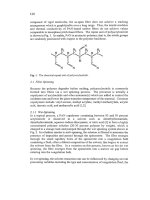
which is also filled with adsorbent as shown in Fig.
1.
3
05
(a)
(b)
Fig.
1.
Simplified adsorption cycle schematic
Initially the whole assembly is at low pressure and temperature, the adsorbent
contains a large concentration of refrigerant within it and the other vessel
contains refrigerant gas (a). The adsorbent vessel (generator) is then heated,
driving out the refrigerant and raising the system pressure. The desorbed
refrigerant condenses as a liquid in the second vessel, rejecting heat (b). Finally
the generator is cooled back to ambient temperature, readsorbing the refrigerant
and reducing the pressure. The reduced pressure above the liquid in the second
vessel causes it to boil, absorbing heat and producing the refrigeration effect.
The cycle is discontinuous since useful cooling only occurs for one half of the
cycle. Two such systems can be operated out
of
phase to provide continuous
cooling.
The above description is of an adsorption cycle which might well use an active
carbon adsorbent. However, it applies equally well to liquid sorbents used in
absorption cycles. The thermodynamics of liquid absorption and solid adsorption
cycles are very similar, although the practicalities are very different. The major,
and obvious, difference is that it is not possible to pump the solid adsorbents
around the system. Given that the whole machine is a heat transfer device, it
would clearly be advantageous to pump the sorbent through a heat exchanger.
There are ways in which a bed of a solid sorbent can be made to behave as if it
has been pumped through a counterflow heat exchanger, but it is more
complicated than if it could be truly pumped like a liquid. Available methods are
discussed in Section
5.2.
Whilst the heat and mass transfer limitations imposed
by the use of a solid adsorbent are a problem, there are a number of advantages
that solid adsorbents have over liquid absorbents.
The fist advantage of solid adsorbents is that they are totally non-volatile unlike
most liquid absorbents. One of the
two
conventional liquid absorption cycle
pairs uses ammonia as the refrigerant and water as the absorbent. In the
generation phase a-b above, when a concentrated ammonia
-
water solution is
heated, the ammonia is driven off but the vapour contains a few percent of water.
This must be removed in a rectifier which preferentially condenses most of the
water vapour and returns it to the generator. Unfortunately
this
reduces the
energy efficiency as well as requiring an additional heat exchanger within the
system. The other commonly used pair uses water as the refrigerant and Lithium
306
Bromide as the absorbent in air conhtioning applications. It does not suffer from
the same problem, since LBr is effectively non-volatile. However, the pair does
have limitations due to the crystallisation limits of LBr in water. In very hot
climates where heat rejection temperatures are higher than about 35°C the pair
cannot be used unless additives are used to move the crystallisation boundary.
The major advantage that solid sorbents have over liquid systems is the large
range of suitable materials available and the ability to engineer them for a
particular application. The number of liquid absorbent
-
refrigerant pairs that
give reasonable performance is very limited and governed by unalterable
chemistry and physics. When using physical adsorption, almost any refrigerant
may be used and in principle an adsorbent can be manufactured with the optimal
pore size distribution for the particular application.
In
summary,
heat-driven cycles for cooling or heat pumping can have energy
saving and environmental benefits. There are also niche applications in
developing countries or remote areas. Adsorption cycles using active carbons are
one of a number of approaches that might be economically viable.
2
The
Basic
Adsorption Cycle
2.
I
Introduction
In order to understand the operation of the cycle and the ideas put forward later
it is useful to look at the essential properties of adsorbent-adsorbate pairs and the
way that they are used in the solar refrigerator.
Adsorbents such as active carbons, zeolites or silica gels can adsorb large
quantities (c.
30%
by weight) of many gases within their micropores. The most
widely used combinations are active carbons with ammonia or methanol, and
zeolites with water, but the choice of which adsorbent and which refrigerant gas
to use depends on the application. The quantity of refrigerant adsorbed depends
on the temperature of the adsorbent and the system pressure. A
good
approximation to the form
of
the function is given by the Dubinin
-
Astakhov
(D-A) equation which is illustrated graphically in Fig.
2
and is commonly
referred to as a Clapeyron diagram.
The following section may be omitted
on
first reading:
In its original formulation, the D-A equation is
307
where
:
V
is the micropore volume filed with the adsorbed phase.
V,
is the limiting micropore volume.
B
is
a function of the micropore structure, decreasing as
microporosity increases.
T
is
the temperature
(K).
p
is the affinity coefficient, which is a property
of
the adsorbate
alone. It is approximated by the ratio
of
the adsorbate volume
with the adsorbed volume
of
a
reference substance (normally
benzene) under the same conditions.
n
is a constant
p
is the system pressure.
p*
is the pressure of the adsorbed phase
within
the micropores.
p'
will vary within the micropores and is impossible to measure directly.
However, the assumption
is
made that the adsorbed phase is analogous
to
saturated liquid at the same temperature, and
pa
may be replaced by
psot
the
saturation pressure of the adsorbate at temperature
T.
At temperatures higher
than
the critical temperature, other estimates for
p*
may be used (Smisak and
Cernf[
11).
The mass concentration
x
can be related to the volume of adsorbed phase
V
by
an assumed density
of
adsorbed phase
r
:
The value
of
r
can be estimated
as
that
of
saturated liquid at the same
temperature or related to supercritical properties at temperatures above critical.
Critoph
[2]
found that for the practical purposes
of
modelling ammonia
-
carbon
adsorption cycles, using experimentally determined porosity data, that the
complexity
of
estimating both
r
andp' at sub and supercritical levels was not
justified. The measured porosity data could be fitted to a much simpler version
of the equation with
no
loss
of
accuracy, as follows:
x=pv
where:
x,
is
the limiting concentration,
k
isaconstant.
Combining this
with
the relationship between saturation pressures and
temperatures:
lnp,,
=
a
-
-
C
where
a
and
c
are constants,
Tat
308
K
is a constant.
T,,,
is the saturation temperature of the adsorbate at the system
pressure (Kelvin).
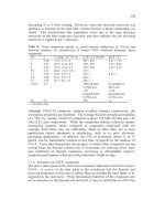
Fig.
2.
Clapeyron diagram showing saturated refrigerant
and
isosteres
Lines of constant concentration (isosteres) are straight when the natural
logarithm
of
pressure is plotted against the inverse of the absolute temperature. It
is conventional to plot against
-1/T
so
that temperature still increases when
moving from left to right. Since adsorbents hold less adsorbate when hot the low
concentration isostere
is
on the right
of
the high concentration isostere. The line
labelled ‘pure refrigerant’ shows the variation of the refrigerant’s saturation
pressure and temperature (i.e. the variation
of
its boiling/condensing temperature
with its pressure). It takes energy (heat of desorption) to drive refrigerant from
the pores and similarly, when gas is adsorbed into the pores heat is generated.
This
is analogous to the latent heat required or generated in boiling or
condensation but is greater
in
size. The heat of desorption per mass
of
refiigerant
is actually proportional to the slope of the isosteres.
309
2.2
The simple solar refi-igerator
Now it is possible to understand the simple solar refrigerator illustrated in Fig.
3
below:
Solar
collector
E
II
I
:vapor
'ator
Cold
box
Fig.
3.
Schematic solar refrigerator
Fig.
3
shows an idealised solar collector (generator) containing adsorbent which
is connected to a condenser that rejects heat to the environment and an insulated
box containing a liquid receiver and a flooded evaporator. Fig.
4
shows the
p-T-x
(pressure
-
temperature
-
concentration or Clapeyron diagram) for the adsorbent-
adsorbate pair with typical temperatures.
The cycle begins in the morning with the generator (solar collector) at ambient
temperature and the evaporator (but not the receiver) full of cold liquid
refrigerant from the previous cycle. The adsorbent contains the maximum
quantity of refrigerant at this time.
As
the sun heats the collector, the adsorbent
temperature rises and some refrigerant is desorbed. Since it is desorbed into a
system of fixed volume the pressure in the system rises. The gas does not
condense because the saturation temperature corresponding to the system
pressure is below ambient temperature.
As
more heat is transferred to the
adsorbent, more gas is desorbed and the pressure rises further. Since the volume
of the gas
in
the system is not large, the mass of gas desorbed is small compared
to that still adsorbed and thus the reduction
in
mass concentration is small. Thus
310
the variation of pressure with adsorbate temperature approximates to that of an
isostere as shown in Fig.
4.
-1
n-
+
-1
0°C
40°C
3
20°C
Fig.
4.
Clapeyron diagram
for
a simple
solar
refrigerator
The situation changes when the system pressure becomes high enough for
refrigerant
to
condense in the condenser and reject the resulting latent heat to the
environment. Further adhtion of heat to the adsorbate desorbs more refngerant
which condenses in the condenser and trickles down into the receiver. The
system pressure stays approximately constant as desorption and condensation
proceed.
The rate at which refrigerant
is
desorbed is limited by heat transfer both
into
the
adsorbent and out of the condenser. The minimum concentration of refrigerant
in
the generator
I
solar collector will be reached at some time during the day when
the it achieves its
maximum
temperature. The receiver will contain its maximum
quantity of liquid refrigerant at
thls
time.
As the incoming solar radiation decreases the collector will drop in temperature
and
so
the adsorbent will now adsorb the surrounding gas, reducing the system
pressure. Heat
of
adsorption is generated in the adsorbent which is rejected to the
environment. At this stage it is beneficial if heat loss from the collector to
ambient can be increased by means of removable insulation, flaps, or some other
method. Since the pressure above the liquid refrigerant in the receiver is reduced,
the liquid boils, replacing the gas adsorbed in the collector. The energy needed
311
for boiling is extracted from the liquid itself and
so
its temperature and pressure
is reduced. For simplicity it is assumed that the insulation around the receiver
is
ideal and none of the energy to boil the liquid is taken from the environment.
As
the collector cools further during the late afternoon and evening the receiver
liquid reaches the temperature of that remaining in the evaporator from the
previous day's cycle. Usually the cooling is used to freeze water which then
keeps the evaporator at a steady temperature despite heat leaking in from the
environment through the insulation. Once the receiver and evaporator are at
an
equal temperature (approximately
OOC)
a new source of heat becomes available.
The energy required for further boiling comes from the warmest source, which
is
now the water
I
ice jacket surrounding the evaporator. Since this results in the
water freezing the evaporating temperature becomes stable and governed by heat
transfer from evaporator to the ice front.
As
the night progresses the refrigerant
desorbed during the day
is
resorbed and enough ice is formed in the cold box to
maintain low temperatures for the following day. Since the rate of cooling
is
normally limited by the rate at which heat can be rejected from the adsorbent
in
the solar collector,
it
is not unusual for this to take many hours. The variation of
pressure with temperature is shown on Fig.
4
both for an actual cycle (dotted
line) and an idealised one consisting of
two
isosteres and
two
isobars.
2.3
The basic continuous adsorption cycle
The simple system above, with no moving parts, is appropriate to a solar
refrigerator with a
1-2
m2 collector on which the cooling load is only a few kilos
of ice production each day. The adsorbent goes through one cycle per day and
for each kilo of ice frozen about
5
kg
of
carbon
is
needed. However, if the
cooling load is equivalent to one tonne of ice per day
(A
domestic air conditioner
might be rated at three tons of refrigeration or about
10
kW) then the mass
of
carbon and refrigerant needed become impractically high. Obviously in such
circumstances it would be preferable to have a rapid cycle in which the
adsorbent were repeatedly heated and cooled every few minutes. The same
adsorbent would be used several hundred times per day rather than once and
the
mass
required could be reduced correspondingly. It is also sensible to have
two
adsorbent beds in which the heating and cooling processes are out of phase.
When one bed is heated the other
is
cooled. This has the advantage of providing
continuous cooling from the system. The beds and the check valves that route
the adsorbing or desorbing gas to the condenser and from the evaporator become
equivalent to the compressor in a conventional refrigerator except that they have
a heat input rather than a work input. This is illustrated in Fig. 5a,b.
3
12
I
Fig.
5a.
Vapour compression
cycle
Fig.
5b.
Basic adsorption
cycle
In
Fig.
5b
the heat flows for one half of the cycle are shown with white fdled
arrows and for the other
half
are shown surrounded by shaded arrows.
The major difficulty in building a practical machine based on this principle is
that in order to heat and cool the beds rapidly, good heat transfer
is
essential.
Unfortunately, by their very nature, adsorbent beds are very poor conductors of
heat. Their thermal conductivity is such
that
they would, in fact, make good
building insulation. It is possible to improve the overall bed conductivity by
incorporating metal
fins
within the bed. However, this increases the thermal
mass of the bed, and every the it is heated, the heat that
is
used to raise the
temperature of the
fins
is in effect wasted. This reduces the overall energy
efficiency of the system significantly. Methods of improving the heat transfer
within the beds
are
described in section
5.3.
Regardless of the problem of heating and cooling the bed
from
external sources
and
sinks,
it is well
known
that the thermal efficiency of the system can be
improved by transferring heat from one bed to another. Instead of directly using
the heat of adsorption rejected by a bed (in the case of a heat pump) or throwing
it away (in the case of a refkigerator) it is better to use it to pre-heat the other bed
thus reducing the input
of
high
grade heat needed from the gas flame or other
source. Indeed, systems using more
than
two
beds have been suggested, which
by transferring heat between the various beds in an optimum manner would
achieve large improvements in energy efficiency. The obvious drawback is
in
the increased complexity and capital cost.
All
of these proposed systems may be
described as regenerative cycles since they use regenerated (or recovered) heat
3
13
from
a
bed which
is
cooling in order to assist the heating of another bed. Some
of these multiple bed systems are described
in
section
5.2.
Before describing advanced cycles and improvements in heat transfer the
thermodynamics
of
the basic cycle
and
the calculation of
COP’S
must be
explained.
3
Basic Cycle Analysis and Results
3.1
Thermodynamic
analysis
poDn
p,
Pig.
6.
Clapeyron diagram for analysis
of
the
basic
cycle
Fig.
6
shows both the actual cycle
(shown
in dashed lines) and the idealised
cycle, which consists
of
two
isosteres and
two
isobars. Heat flows in Jkg
adsorbent
(4)
are shown as shaded arrows. For most purposes, analysis of the
ideal cycle gives an adequate estimate of the
COP
and cooling or heating per kg
of adsorbent. An accurate calculation of the path of the actual cycle needs
information on
the
dead volume of the whole system and of the heat transfer
characteristics of the condenser and evaporator. General trends are more
apparent from an analysis of the idealised cycle.
-1
JT
3
14
The
COP
in cooling
(COPc)
or heating
(COP,)
is defied by:
+
q34
+
q41
COP,
=
qev
,
COP,
=
qcOn
q12
'
q23 q12 +q23
Considering the processes occurring in Fig.
6
in sequence:
Process
1-2
The heat input per unit
mass of
adsorbent in the isosteric heating phase when the
concentration is
x,,,
is given by:
T2
G
where
:
CPC
~mnc
cw
TI
T2
=
Specific heat of adsorbent (carbon), possibly a fimction of
temperature.
=
maximum concentration, obtained at point
1
by using the evaporating
pressure and bed temperature
TI
in the Dubinin-Astakhov equation.
=
Specific heat of adsorbed phase at constant volume.
=
minimum cycle temperature
(K).
=
temperature at start of desorption
(K).
The integrated terms are simply the specific heat of the unit mass of adsorbent
and its associated adsorbate. The specific heat at constant volume has been used
for the adsorbate since, theoretically, there is no expansion of the adsorbate
volume and the heat required to raise the temperature is the change in internal
energy. In practice there will be some expansion and a pessimistically high
estimate could use the specific heat at constant pressure
cp.
The specific heat of
the adsorbed phase is in any case difficult to estimate and it is common to
approximate it to that of saturated liquid adsorbate at the same temperature.
T, is easily calculated, since the
ratio
of
T
/To,
is constant along an isostere,
giving:
Process
2-3
The heat input per unit
mass
of
adsorbent in the isobaric heating phase where the
concentration varies is given by:
315
where
xdzl
is
the
minimum
concentration and
H
is the heat
of
desorption per unit
mass
of
adsorbate.
H
at any point on
2-3
or 4-1 can be derived from the slope
of
the isostere
on
the Clapeyron diagram
(A):
H=RA
where:
R
=
The gas constant at the system pressure and temperature.
Assuming the
form
of
the Dubinin equation to be correct, or more generally
that the ratio
T/Cat
is constant along
an
isostere then
H
can be expressed as a
multiple
of
the latent heat
L
of
the refrigerant at the system pressure:
H=L-
T
?at
Process
3-4
The heat rejected per unit mass
of
carbon
in
the isosteric process 3-4
(
qj4
)
is, by
analogy with process 1-2
:
T3
q34
=
I(
'pc
+
xdil
'VQ)
dT
=4
where
T4
may be calculated
from:
Process
4-1
The heat rejected per unit
mass
of
carbon in the isobaric process
4-1
(q41
)
is
similarly analogous to process 2-3:
T4
Xcmc
J(
'pc
+
'p~
)
dT
-k
q41
-
[
'gus
bed
-
'~QS
m])&
T
xrm
where:
h,
bed
h,
ey
The fiist term
in
the second integral will not have de same magnitude as in the
desorption process because the latent heat
L
will now be that at the evaporating
is the gas enthalpy evaluated at the bed temperature (Jkg),
is the gas enthalpy evaluated at the evaporator
(Jkg).
316
temperature rather than at the condensing temperature. The second bracketed
term in the second integral takes account of the cooling effect on the bed of the
cold gas entering from the evaporator.
Cooling (evaporation)
Finally, the cooling and the heat rejected in the condenser must be evaluated.
The
mass
of
refrigerant desorbed and then adsorbed per unit
mass
of adsorbent
during every cycle is
xconc
-
xdjl
.
The useful cooling obtained from it is:
qev
=
(xconc
-
xdil)(
hgm
ev
-
‘liquid
cox)
where:
hgus
ev
hhquidcon
is the specific enthalpy of the condensed liquid (Jkg).
is the specific enthalpy of gas leaving the evaporator
(Jkg),
This formulation applies both to the use of a semi-continuous cycle with an
expansion valve and to a discontinuous cycle (such as that in the solar
refrigerator) using a flooded evaporator in which the warm condensate must first
cool itself before it can cool the load.
Condensation heat
The heat rejected at the condenser is the
sum
of the condensation heat and that
required to cool the gas down
to
the condensing temperature. Since the gas is
desorbed at a range of temperatures between
T2
and
T3
this should properly be
evaluated as:
xconc
qcon
=
-
jhgasdx
-
hiiquid
(xconc
-
xdil)
xdrl
where:
h,
hllYurd
is the gas enthalpy evaluated at the (varying) bed temperature,
is the saturated liquid enthalpy in the condenser.
In
practice there is only a small error if the hot gas is all assumed to leave the
bed at the mean temperature of
T2
and
T3 .
3.2
Eficiency
of
the basic cycle
Whilst the above analysis is detailed and quite complex, there are general trends
that become apparent relating to how both the carbon properties and the
operating conditions affect the
COP’S
of
adsorption heat pumps and
refrigerators. The cooling available from the cycle is approximately proportional
to the difference between the high and low concentrations and to the latent heat
of the refrigerant. The heat input
to
the cycle has three components: the sensible
317
heat load of
the
carbon, the sensible heat load of
the
adsorbed phase and the heat
of desorption.
There is an obvious benefit if both
x,,,,
is large (in order to minimise the effect
of
the carbon sensible heat load) and
xdiI
is
small (to maximise the cooling
effect). There would be
an
additional benefit if the isosteres were closely
grouped in the region where desorption begins. This would correspond to a large
concentration change over a small temperature rise, which reduces the peak
cycle temperature and the heat input required. The ideal would be to drive out all
of the refrigerant at one temperature.
This
would be similar to a chemical
reaction and there are cycles based on reactions such as those between calcium
chloride and ammonia
or
methanol. They have the advantage that many moles
of
refiigerant may be desorbed at one temperature but suffer problems due to
swelling of the adsorbent and the dynamics
of
the reaction which are not present
in physical adsorption. It is also clear that there will always be an optimum of
the peak cycle temperature for the greatest
COP.
The bed must be heated to
T,
in
order to desorb
any
refrigerant and achieve any cooling at all. As
T3
is increased
the
quantity of refnigerant desorbed increases, as does the
COP
initially.
However, at higher temperatures the quantity
of
refkigerant desorbed per degree
temperature rise is less. Eventually the benefit
of
the extra cooling derived by
desorbing a little more refrigerant is offset by the disadvantage
of
the extra
sensible heat load of the bed.
These effects are illustrated in Fig.
7
which shows a set of isosteres for a typical
adsorbent with ammonia refrigerant. Fig.
7
shows
a refrigeration cycle with
evaporating temperature of
-1OOC
and condensing temperature of 30°C. The
adsorption heat is rejected down to
30°C
and the maximum cycle temperature
is
15OOC.
Raising this maximum to
200°C
would result in the minimum
concentration decreasing
3.5%
and the cooling effect increasing
30%.
However,
the heat input required increases more rapidly and the
COP
drops from 0.375 to
0.366. The diagram also illustrates the effect of changing the cooling
temperature and heat rejection temperatures. If the evaporating temperature goes
down whist
the
other temperatures remain the same then
x,,,
will be reduced
since the minimum system pressure is lower,
x,,
is
unaltered and
so
the
concentration change, the cooling per mass of carbon and the
COP
are all
reduced. Increasing the condensing temperature
will
increase
xdIl
,
also
reducing
the concentration change and COP. Raising the heat rejection temperature
TI
will
reduce
x,,,
and hence the
COP.
These effects are as would be expected from a
consideration of the global thermodynamic effect of lowering the evaporating
temperature
or
raising heat rejection temperatures.
318
lDOOlT
w')
Fig.
7.
Typical ammonia
-
carbon basic cycle
4
COP
0.3
-
50'
c
60'
C
0.2
-
0.1
0
80
100
120
140
160
180
200
220
240
Maximum
bed
temperature
7,
(
'C)
Fig.
8.
Effect
of
heat rejection temperature and maximum cycle temperature on
refrigeration
COP
3
19
The variation of refrigeration
COP
with
heat rejection temperature (final bed
adsorption temperature and condensing temperature are assumed equal) and the
maximum cycle temperature is illustrated for an evaporating temperature of
-5°C
in Fig.
8.
Heat pump
COP’s
follow similar trends but are higher.
4
Choice
of
Refrigerant
-
Adsorbent
Pairs
The above discussion describes how cycle performance varies with the different
external temperatures, but naturally the choice of adsorbent and refrigerant pairs
used will also have a major effect. Most refrigerants can be adsorbed by carbons,
but the most useful ones have a high latent heat. Any active carbon will have a
maximum
micropore volume which can contain the refrigerant in its adsorbed
state. The
maximum
cooling that could possibly be achieved by totally desorbing
and then adsorbing
in
a single cycle is the product of the liquid refrigerant’s
latent heat and the mass of adsorbed refrigerant that totally
fills
the micropores.
Assuming some similarity between the adsorbed and liquid phases, refrigerants
with high latent heat per unit liquid volume will give better performance.
Table
1
gives a selection of possible refrigerants with suitably high latent heats,
all of which tend
to
have small polar molecules. The table is split into two
groups: those with normal boiling temperatures above and below
-10°C.
The
properties are taken at the normal boiling point. Attainable
COP’s
correlate
reasonably with the latent heat per unit volume. Of the high pressure
refrigerants, ammonia is the best available. Although toxic and incompatible
with copper and brass, it has no ozone depletion potential and
is
not a
greenhouse gas. It
is
used widely as a refrigerant in industry and is being
considered increasingly as an environmentally friendly refi-igerant for other
applications.
The best sub-atmospheric refrigerant is water. Unfortunately it is not strongly
adsorbed by carbons, but refrigerators and heat pumps based on water
-
zeolite
pairs have been built and tested
in
research laboratories. Methanol
is
adsorbed
well by carbons and a solar refrigerator based on a carbon
-
methanol pair was
marketed by Brissoneau et Lotz Marine in France. Methanol is environmentally
friendly, but decomposes at temperatures
around
150°C
and
so
cannot be used
for very high temperature cycles.
High pressure
and
sub-atmospheric cycles have different advantages and
disadvantages. The choice between them will depend on the application.
Low
pressure cycles require perfect hermetic sealing against air ingress. Any air
leaking into the system
will
migrate to the condenser, where
it
will impede the
condensation process and eventually cause failure. Low pressure machines also