Carbon Materials for Advanced Technologies Part 13 pptx
Bạn đang xem bản rút gọn của tài liệu. Xem và tải ngay bản đầy đủ của tài liệu tại đây (565.16 KB, 35 trang )
400
3
Irradiation Effects on Thermophysical Properties
of
Graphite and Carbon
Fiber Composites
3.1
Radiation
displacement
of
atoms
Radiation effects
in
the graphite PFM can be categorized as near surface damage
caused by interaction with the plasma, andlor bulk displacements caused by
neutrons emanating from the plasma or back scattered by the surrounding structure.
Amongst present day machines, only the
TFTR
has significant
D+T
fusion
reactions and, therefore, experiences a damaging
flux
of
fusion neutrons (see
Eq.
1).
However, because
TFTR
will undergo only a limited number of low power
plasma
"shots,7'
the neutron dose will not be high enough for the
PFCs
and
structural materials to experience appreciable neutron damage. In contrast,
however, machines such as the
ITER
will experience significant neutron doses.
Moreover, the next generation
D+D
machines such as the proposed
TPX,
will yield
enough tritium to produce
(D+T
and
D+D)
fusion neutrons at levels sufficient to
alter graphite properties.
High energy particles which travel through matter can interact with their
surroundings.
As
the particles interact with matter they lose energy (per unit path
length)
in
three ways: elastic collisions, electron excitations,
and
nuclear
interactions. The interaction which is of primary interest from the materials point
of view are the elastic collisions. If an ion or a neutron
imparts
Sufficient energy
to overcome
an
atom's binding energy
(Ed
carbon
=
20
-
30
ev), the carbon is
displaced
from
its original lattice position. If the energy transferred to the
displaced atom (less
its
binding energy) is sufficient to displace
further
atoms, a
series
of
displacement events or a "cascade" occurs.
In
the simplest interpretation,
the Kinchin-Pease
[3]
model is used to calculate the total number of atoms
displaced. For example, if a carbon atom were ejected by the plasma and re-
impacted onto
the
carbon tile with a kinetic energy
E
of
1
KeV, the estimated
number of atoms displaced
(n)
is estimated as follows
:
n
=
(E/2*Ed)
=
25
atoms
(5)
The interaction of high energy neutrons with matter is very similar to that of ions.
The primary difference between the
two
being the amount of energy transferred in
a single collision, and the distance over which the interactions take place. An ion,
which has a relatively large radius and interacts coulombically, loses its energy
over a short path length (typically less than a micron).
In
contrast, the
comparatively small uncharged
14.1
MeV fusion neutron which undergoes only
simple elastic
or
"billiard baU" collisions,
has
a
mean free path of
-
10
cm.
So,
on
average, a fusion neutron will have
an
elastic collision with a carbon atom once
in
10
cm
of
graphite. The amount of energy transferred to the carbon
in
this
fifst
collision
(Ec)
is calculated by simple elastic theory as:
4x6~1
(6
+
1)'
3
Eocos'a
=
[
]
(14.1
MeV)cos'a
(6)
4momn
Eo
=
[
(me
+
",)'
where
m,
and
rn,,
are the carbon and neutron
mass
(in
mu),
respectively,
E,
is the
neutron energy, and
a
is the angle between neutxon path before and after the
collision. For a totally back scattered neutron (the maximum imparted energy) the
energy transferred to the displaced carbon
is
4
MeV. From Eq. 5, the number of
hsplaced carbon atoms resulting from this
4
MeV neutron displacement event is
approximately
80,000.
The vast majority of these atoms do not stay "displaced,"
but diffuse back into the graphitic structure within a few picoseconds.
To
assess
the effects such collision events have on a material, a convention has been adopted
to compare irradiation doses. The displacement per atom, dpa, is the average
number of times an atom
has
been knocked from
its
original lattice position. The
dpa is an integrated average quantity and takes into account the density, the
interaction cross section, and neutron energy spectrum. It has been estimated that
lifetime displacement levels in
TPX
PFCs
will be about
0.005
dpa, while the
physics phase of
ITER
will
accumulate approximately
1
dpa. In the second phase
of
ITER,
which more closely represents a power producing system, as much as
30
dpa is expected.
3.2 Suglace
efects
In certain areas of a fusion machine
the
PFMs
receive displacement levels much
greater than
100
dpa, but only within the limited collisional range of the plasma
ions,
typically less than a few microns. The effect of
this
high damage level
will
be to reduce a well graphitized structure into one which appears
amorphous.
However, these near surface regions are subjected to erosion either by physical
sputtering (caused by elastic collisions), or by chemical interactions. Both of these
effects are addressed
in
Section
4.
A second surface radiation damage issue
(i.e.,
the ability of the thin damaged surface layer to retain and transport hydrogen) is
discussed in Section
5.
3.3
Effects
of
neutron
displacements
on
graphite
apld
carbon
fiber
composites
As
discussed earlier, the first wall materials in next generation machines will
receive from
0.005
to
30
displacements per atom. At the lower end of this range
(<0.01
dpa) there are essentially
no
mechanical property changes expected
in
graphite materials. However, even at these low doses thermal conductivity and
stored energy are
of
concern. For displacement levels
>0.01
dpa other property
402
changes are sigaificant: strength, elastic modulus, specific heat
(Cp),
CTE,
Poisson's
ratio
(v),
and thermal conductivity.
In
addition, the dimensional stability
under
irradiation
is
important because the induced stresses may be significant, and
because of the need for very tight dimensional tolerances at the plasma edge. It has
been shown in fission neutron experiments that Cp
[4]
and
v
[5]
are not greatly
affected by irradiation. Moreover, only moderate changes in the
CTE
occur, but
the magnitude and nature of the CTE change
is
highly dependent on the type of
graphite
[4,6-81.
The irradiation-induced graphite and CFC property changes which have received
the most study by the fusion community are the dimensions, strength, elastic
modulus, thermal conductivity, and hydrogen retention. A large body of
data
exists
on the thermophysical changes in graphites, coming mainly from graphite
moderated fission reactor development program.
A
smaller body of data exists on
CFCs, mainly from the same source, but with some additional data from fusion
research.
These data suggest that CFCs have similar irradiation behavior to
graphite. In Chapter
13,
Burchell discusses radiation damage mechanisms in
graphite, and some of the specific property changes which
occur.
Because
of
their
special signikance to fusion energy, the remainder of
this
section
will
focus on the
radiation effects in CFCs and on radiation-induced degradation in thermal
conductivity in graphite and CFCs.
3.3.1 Dimensional changes in carbon fiber composites
A
discussed
in
Chapter 13, irradiation-induced dimensional changes
in
graphite are
highly anisotropic, and
a
strong function of irradiation temperature and neutron
dose (dpa). The temperature range of interest for fusion applications varies from
100°C in areas well removed from the plasma, to over 1000°C for the surface of
PFCs which experience appreciable plasma
flux.
The mechanism of graphite
irradiation-induced dimensional change is descriied
in
detail in Chapter 13, and
is
a combination of intra- and inter-crystallite effects. Within the crystallites,
displacement damage causes
an
a-axis shrinkage (within the basal plane) and a
c-
axis growth (perpendicular to the basal plane).
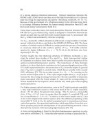
Similar dimensional change behavior has been observed in CFCs
[9].
Figure
5
shows the dimensional change behavior
of
one-,
two-,
and three-directional
composites.
In
this
example, solid cylinders were irradiated at
60OOC
to
doses
ranging from
0-5
dpa and the resulting diameter and length measured. The
behavior of each material can be explained by the accepted theory for dimensional
change
in
graphite (Chapter 13) after taking
into
account the individual fiber
architectures, and by observing that a graphite fiber, PAN-based in this example,
is
basically a filament of circumferential or radial basal planes running pardlel to
the fiber axis. The irradiation-induced dimensional change of such a fiber
is
therefore to
shrink
in length and grow in diameter, as observed for the
403
unidirectional composite
of
Fig.
5.
At doses less than 1 dpa the dimensional
change is relatively minor. As the dose is increased, the direction perpendicular to
the fiber axis is more or less unchanged while a significant shrinkage along the
direction parallel to the fiber axis occurs. At about
2
to 3 dpa swelling in the
composite occurs in the perpendicdar direction. The random fiber composite
of
Fig.
5
has a random orientation of chopped
PAN
fibers in the plane
of
the
composite. The specimen diameter shows practically no change perpendicular
to
the fiber
axis
to about
4.5
dpa, though exhibits
-2%
shrinkage parallel to the fiber
axis. The
3-D balanced PAN-weave fiber
has
essentially isotropic shrinkage to a
dose of
-2
dpa, at which point the diameter
of
the fibers, and hence the sample,
begin to swell.
Also
given in the 3-D composite plot in Fig.
5
is the radiation-induced dimensional
change behavior parallel to the fiber axis
of
an Amoco
P55
pitch fiber composite.
This
material was processed in an identical manner to the PAN fiber composite.
From the plot it appears that the pitch fibers, and thus the composite, undergo
slightly less shrinkage than the
PAN
fiber composite, possibly due to the higher
fiber crystallinity.
This
hypothesis is also supported by the observation that fibers
with hgher final heat treatment temperatures tend to e~bit less dimension change
[
101
and
is
also consistent with the observation that elevating the heat treatment
temperature of graphite reduces the irradiation-induced shrinkage
[
1
11.
3.3.2
Changes
in
strength and modulus
A
marked increase in both strength and elastic modulus occurs in graphite and
CFCs
at dose levels as low as
0.01
dpa
[6].
These increases continue to high
hsplacement levels until volumetric expansion and extensive micro-cracking occur
and the material begins to degrade. Structural degradation typically occurs at
several
to
tens of dpa depending on the graphite type and irradiation temperature.
The initial increase in modulus
is
a result of dislocation pinning by lattice defects
produced by neutron irradiation. The magnitude
of
the increase
is
dependent on
the perfection
of
the graphites. For most graphites a modulus increase
of
2
to
2.5
times the unirradiated value
is
typical for irradiation temperatures less than
300"C,
with the change becoming less pronounced at higher irradiation temperatures.
Irrahation-induced increase in strength occurs
in
a similar fashion as the elastic
modulus. The irradiated and unirradiated mechanical properties of some candidate
ITER
PFC
materials are shown in Table
2.
These materials were irradiated at
approximately
1000°C to a dose
of
about
2
dpa
[12J
The change in properties
is
relatively small because
of
the high irradiation temperature.
3.3.3
Thermal conductivity degradation
The irradiation-induced thermal conductivity degradation
of
graphites and
CFCs
will cause serious problems
in
fusion system
PFCs.
As with ceramics, the thermal
conductivity of graphite
is
dominated by phonon transport and is therefore greatly
404
affected by lattice defects, such as those caused by neutron irradiation. The extent
of the thermal conductivity reduction is therefore controlled by the efficiency of
creating and annealing lattice defects and is, therefore, related to the irradiation
temperature.
1
I , , ,
~'
UNIIXRGCTIONM.
WEER
COMPOSITE
(VFC)
-1
-
-2
0
1
2
3
4
5
0.5
RANDOM
FIBER
(RPC)
MMPOSlTE
-0.5
OPT
0
1
2
3
4
5
0
1
2
3
4
5
Neutron
Dove
(dpaf
Fig.
5.
Neutron irradiation induced dimensional changes in graphite composites.
405
The effect of neutron irradiation on the thermal conductivity of graphite has been
widely studied. The majority of the literature
[8,
10,
13-21] in this area has been
in support
of
the gas-cooled, graphite-moderated, fission reactor program
in
the
United States and United Kingdom and
has
focused on "nuclear" graphites as well
as more fundamental work on pyrolitic graphite [6,17,22,23].
In
recent years, the
emphasis of radiation effects research
has
switched to graphites used in plasma-
facing components
of
fusion reactors
[8,24-271.
As
discussed in Sections
2.2
and 2.3, composites with very high thermal
conductivity are desirable because of the hgh heat
flux
present in certain areas of
fusion devices. Because of the significant advances in processing of
CFCs
ad
fiber development, very high thermal conductivity materials have been recently
demonstrated and become attractive for high heat flux applications. The highest
thermal conductivities have been demonstrated for
CFCs
made from highly
crystalline graphite fibers which have intrinsic conductivities approaching that
of
pyrolitic graphite. For example, vapor grown carbon fibers
[28]
have a thermal
conductivity
of
1950
W/m-K.
The physical processes governing the thermal conductivity of graphites, as well as
the mechanisms responsible for the radiation-induced degradation in conductivity,
are well established
[6].
For all but the poorest grades
of
carbon, the thermal
conductivity
is
dominated by phonon transport along the graphite basal planes and
is reduced by scattering "obstacles" such as grain boundaries and lattice defects.
For graphites with the largest crystallites
(i.e.
pyrolitic or
natural
flake graphite) the
in-plane room temperature thermal conductivity is approximately 2000
W/m-K
~91.
The thermal conductivity of graphite-based materials can be written as a
summation of the
thd
resistance due to scattering:
1
1 1
-1
K(x)
=
P(x)
[-
+
-
+
-1
K"
Kgb
K,
(7)
where p(x) is a coefficient which includes
terms
due to orientation (with respect to
the basal plane), porosity, and some other minor contributors. This coefficient
is,
in most cases, assumed
to
be constant with temperature, with a value
of
around
0.6.
The fmt
two
terms inside the parentheses are the contributions to the thermal
conductivity due to Umklapp scattering
(IC)
and the grain boundary scattering
(I&,,).
The grain boundary phonon scattering dominates the thermal resistance
(l/Kgb)
at low temperatures and is insignificant above a few hundred degrees
Celsius, dependmg
on
the perfection of the graphite. The Umklapp scattering,
which defines the phonon-phonon scattering effect on the thermal conductivity,
P
0
m
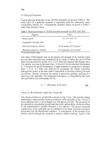
Table
2.
Effect of neutron irradiation
on
some graphite or CFC materials studied
for
fusion applications
[I21
Mitsubishi Kasei
MKC-1PH
CFC
Showa-Denko
Toyo
Tanso
CX-
to yo-Tanso
CC-3
12
Felt CFC
2002U
CFC
Property
IG-110 Graphite
(11
ti
fibers)
X-direction Y-direction Z-direction
(1
to
fibers)
Young’s Modulus
(GW
Unirradiated
8.83 34.0 74.0
87.6 14.9
Irradiated
11.5 31.3 98.0
__
87.2
18.5
Bending Strengh
Unirradiated
35.2+/-1.8
90.5+/-5.9 1 03.9+/-6.8
5.8+/-2.5
99.2+/-
1
7.6 36.3+/-3.9
Irradiated
3 8.4+/-2.2 110.8+/-8.4
98.4+/-2.7
88.9+/-8.2
46.7+/-2.6
Compressive
Strength (ma)
Unirradiated
85 .O+/-2.6
65.1+/-2.5 59.8+/-6.8
76.7+/- 14.0
5 9.6+/-6.7 33.3+/-8.7
Irradiated
82.0+/-3.2 93.7
55.9+/-3.1
51.0t-1-7.3
41.2+/-9.2
Length Change
-0.12 -0.30 -0.39
-0.97 -0.195
l/lo(%)
407
dominates at higher temperatures and scales nearly as T2 [6]. The Umklapp
scattering therefore defines the upper limit to the thermal conductivity for a
"perfect" graphite. Following Taylor's analysis [30], the Umklapp-limited thermal
conductivity of the graphite crystal would be -2200 W/m-K at room temperature,
in close agreement with the best pyrolitic graphites, or the vapor grown carbon
fibers mentioned earlier.
The third term
in
Eq.
7,
K,,
is the contribution to the basal plane thermal resistance
due to defect scattering. Neutron irradiation causes various types of defects to be
produced depending on the irradiation temperature. These defects are very
effective
in
scattering phonons, even at
flux
levels which would be considered
modest for most nuclear applications, and quickly dominate the other terms in
Eq.
7. Several types of irradiation-induced defects have been identified
in
graplute.
For irradiation temperatures lower than 650"C, simple point defects in the form of
vacancies or interstitials, along with small interstitial clusters, are the predominant
defects. Moreover, at an irradiation temperature near 150°C
[
171 the defect which
dominates the thermal resistance is the lattice vacancy.
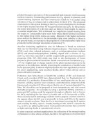
Due to its sensitivity to the presence of defects, the temperature at which graphite
is irradiated has a profound influence on the thermal conductivity degradation. As
an example, Fig.
6
shows one
of
the most complete sets of irradiation data on Pile
Grade A (PGA) nuclear graphite 1311. PGA is a melum-grained, extruded,
anisotropic material with a room temperature thermal conductivity of 172 Wlm-K
in the extrusion direction. Figure 6 presents the normalized room temperature
thermal conductivity of
hs
graphite at various irradiation temperatures. It is seen
that as the irradiation temperature is decreased, the degradation in thermal
conductivity becomes more pronounced. For example, following irradiation at
1
50°C,
the thermal conductivity of this graphite appears to approach an asymptotic
thermal conductivity of -1% of original. As the irradiation temperature
is
increased, and the corresponding interstitial mobility becomes more significant?
fewer defects remain in the structure and the thermal conductivity is reduced to a
lesser extent. It is important to note that the data in Fig. 6 are from ambient
temperature measurements and therefore underestimate the normalized thermal
conductivity at the irradiation temperature,
i.
e.,
K,JTim)/Kunir(T).
Data have been published for CFCs whos thermal conductivities are similar
to
nuclear graphites, and show degradation similar to that expected from the graphite
literature. For example, Burchell [24] has shown that the saturation thermal
conductivity for a 3-directional composite (€341-222,
Lm
=
200 W/m-K) is -40%
of the original room temperature conductivity following fast neutron irradiation at
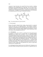
600°C. Published data for the degradation of thermal conductivity in highly
conductive CFCs have led to the conclusion that a higher initial conductivity results
in a greater absolute conductivity reduction after irradiation [24, 321. Figure 7
408
0.4
I
I
f
1
Pile Grade
A
Graphite
Measured at
Ambient
0.35
-1
"\si
0.15
-:
450 OC
0.1
-;
0.05
-+
0
I
0.1
1
10
DPA
Fig.
6.
Normalized thermal conductivity
of
neutron irradiated pile grade
A
graphite
demonshates this point. For the extremely damaging irradiation temperature of
-2OO0C, it
is
seen in Fig. 7 that the absolute reduction
(l!&,,m-KJ
is substantially
greater for the high thermal conductivity materials compared to the lower grade
CFCs and graphite, although the normalized fraction is approximately
the same for all of the carbon materials in Fig.
7.
Moreover, a saturation in thermal
conductivity degradation occurs, at a neutron dose
of
-
1
dpa. Data for higher
irradiation temperatures 1271 shows that the higher thermal conductivity materials
have a slightly larger fractional change in thermal conductivity
(K,,.,lK,,,,in)
compared to lower conductivity materials, although the absolute value of the
irradiated thermal conductivity is still greater for the higher conductivity materials.
An algorithm
has
been developed to predict the thermal conductivity degradation
for a high thermal conductivity composite (-555 W/m-K at room temperature) as
a fimction
of
radiation dose and temperature 1331. The absence
of
irradiation data
on CFCs of this type required the use of data from intermediate thermal
conductivity materials as well
as
pyrolitic graphite to derive an empirical radiation
damage term
114,
17,
19,
25,261.
409
700
600
500
400
300
200
100
0
I
1
I
Tfn=200°C,HpIRCme
-
Measurements
at
Ambient
1
0.0
0.01
0.1
Neutron
Fluence
(DPA)
Fig.
7.
Irradiation induced thermaI conductivity degradation
of
selected graphite materials.
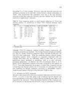
An
analysis of the effects
of
temperature and neutron dose on the thermal
conductivity is shown in Fig.
8.
Specifically, the algorithm assumed the
unirradiated properties
of
the unidirectional fiber composite,
MKC-lPH,
and is
coupled with an empirical radiation damage term.
As
with the experimental data
of Figs.
6
and
7,
it
is
seen
in
Fig.
8
that an enormous loss
in
thermal conductivity
occurs at low irradiation temperatures. Presently, only a few data points exist
which are relevant to the validation ofthis algorithm, and these are also plotted on
the Figure
[25].
The data agree within the errors of irradiation temperature and
thermal conductivity measurement
with
the algorithm predictions. However, they
are insufficient to validate the algorithm
and,
clearly, the need exists for additional
data for
th~s
purpose.
To
illustrate the usefulness
of
such an algorithm, and the seriousness of the issue
of thermal conductivity degradation to the design and operation of
PFCs,
the
algorithm discussed above
has
been used
to
construct Fig.
9
[34],
which shows the
isotherms for a monoblock divertor element
in
the unirradiated and irradiated state
and the "flat plate" divertor element
in
the irradiated state.
In
constructing Fig.
9,
the thermal conductivity saturation level
of
1 dpa given in Fig.
8
is assumed, and
the flat plate and monoblock divertor shown are receiving a steady state flux of
410
0
-
Data
fmm Bond,
et
d.
-0.1
dpa
-
-0.5
dpa
-
dpa=displarement per
atom
-1
dpa
-
l*l,l.l,l,l#l,l*-
I
Fig.
8.
Calculated thermal conductivity
of
neutron irradiated
MKC-
1
PH
composite.
15 MW/m2. Both composite materials have been assumed to be
in
perfect contact
with a copper coolant tube or plate. Figure
9
clearly illustrates
two
points. First,
a very high conductivity composite is required to handle the extreme heat fluxes
expected and to limit the surface temperature to
<
1200°C
(Section
4).
Second, the
effect of neutron irradiation on the conductivity is significant. For the case of the
flat plate divertor the temperature rise
(AT)
changes from
-200
to -500°C
following irradiation, while for the monoblock it increases from -350 to -900°C.
It should be noted that the larger temperature increase for the monoblock design
is not due to the larger path length of graphite in that configuration, but rather to
the larger amount of graphite material which
is
irradiated in the highly damaging
low temperature regime (see Figs.
6
or
8).
The
larger temperature increase for the
monoblock design could be unacceptable from an erosion standpoint as will be
discussed in Section
4.
Monoblock
Design
Tmu-
i40
'C
41
1
Flat
Plate Design
Tmsx=
920
OC
i1
8
mm
_1
33
6
mrn
.
870
'
700
520
'
3w
3w
220
im
130
150
220
290
Unirradiated
140
1-3
dpa Irradiation
1-3
dpa Irradiation
Fig.
9.
Temperature
contour
for
irradiated
and
unirradiated graphite divertor tiles.
Because of the serious thermal conductivity degradation in graphite, operating
scenarios which limit
this
problem (such as baking the PFM) have been considered.
Upon annealing above the irradiation temperature, interstitial atoms become mobile
and can recombine with the vacancies, restoring the thermal conductivity of the
lattice. It is, therefore, conceivable that intermittent annealing of the PFC could
regain some of the irradiation-induced thermal conductivity degradation. Bake-
outs are typically conducted between operating cycles of a fusion system for
plasma impurity (usually oxygen) control. However, the wall conditioning
temperatures are typically limited to less than
300°C
and for various reasons can
not be significantly increased. Inspection of
data
such as that given in Fig.
10
[33]
indicates that little recovery in thermal conductivity is possible unless bake-out
temperatures approach
1000°C.
Thus, in-situ annealing can be of only marginal
benefit.
0
200
400
600
800
1000
1200
1400
1600
Annealing
Tcmperirture
f"C)
Fig. 10.
The effect
of
annealing on the
normalized
thermal
conductivity
of
irradiated
graphite
and
graphite composites.
4
Plasma Wall
Interactions
A
range of particle types, fluxes, and energies strlke the
PFCs
and interact in the
near surface region. The most common interactions are with hydrogen fuel ions,
whch can range
in
energy from a few eV to hundreds of eV. In addition to
hydrogen ions, fuel by-product ions such as helium and impurities from the first
wall also impact the surface. Severe surface layer damage occurs because of such
ion impacts, and significant erosion of surface material addtionally occurs.
Various mechanisms are responsible for erosion, depending on the surface
temperature of the graphite. The mechanisms can be generally characterized in
order of increasing temperature phenomenon as: physical sputtering, chemical
erosion, and radiation enhanced sublimation (Fig.
11)
[35]. Above
2000°C
the
vapor pressure of graphite dominates the erosion.
4.1
Physical
sputtering
When an impacting particle transfers energy to a near surface carbon atom in an
amount sufficient to overcome the lattice bond energy or surface binding energy,
some carbon atoms may be displaced and move in a direction defined by the angie
413
1
A
3bVHe
0.1
0.01
,
Sublimation
0.001
0
200
460
600
880
'1000
12Lfo
1300
2600
Temperature
(Cf
Fig.
11.
Sputtering
yield
as
a
function of temperature for graphite.
between its path and the initial path of the impacting atom. Analogous to strlking
a billiard ball, this angle must be between
0
and
90".
The energy imparted to the
displaced atom follows the same form as that given in Eq.
6.
For an atom striking
a surface normally, the recoiling atom can not be sputtered
from
the surface.
However, for an off-normal angle of impact, or when considering displacement
cascade events which occurs near the surface, some fraction of atoms will be
emitted (physically sputtered) from the graphite surface. The amount of material
lost from the surface is defined by the sputtering yield
(9,
which is the number
of
target PFM atoms emitted per plasma ion impacting the surface. From
Eq.
6
we
see that the energy transferred, and thus the erosion yield, is a strong function of
the impacting particle mass and the mass of the material being sputtered. The
impact angle also has a large effect on the number of atoms which receive adequate
kinetic energy normal to the
PFM
surface to be physically sputtered. The plasma
ions travel along the magnetic field lines which are at a shallow (grazing) angle
with the PFM, typically
1
to
5
degrees, and the ion impact angle will be modified
by
surface potentials and collisional processes.
The quantitative effect
of
the mass, energy, and angle
of
impact on the sputter yield
for impacting deuterium ions
is
shown in Figs. 12a and b.
As
the kinetic energy
414
of the deuterium increases the total amount of energy transferred to the target
atoms increases, as does the average amount
of
energy per collision, resulting in
greater erosion. From Fig. 12a it may be seen that the physical sputtering yield of
light target atoms is considerably greater than for the heavy atoms, primarily due
to the reduced impact energy required to overcome the displacement energy of the
higher-Z target atoms. For example, approximately 20 eV is required to hsplace
an atom of carbon
from
the surface, while 220 eV is required for
an
atom of
tungsten.
In
the sub-keV energy range of plasma fuels, the high yield materials are
therefore carbon and beryllium. As the impacting ion energy increases, the
sputtering yield for all materials decreases as the depth of interaction of the
impacting ion becomes too great for displaced atoms to back scatter to the surface.
In the case of graphite, the majority of the displaced material comes from the top
few atomic layers [36].
With the correct combination of incident energy and target mass it
is
possible for
the sputtering yield to exceed unity,
i.
e.,
more than one atom leaves the surface for
every particle impacting it. This quickly leads
to
what is called the catastrophic
'lcarbon bloom,"
i.e.,
self accelerating sputtering of carbon.
As
can be seen in
Fig. 12b,
this
problem is worst for carbon self-impacts at grazing angles to the
surface.
4.2
Chemical
erosion
For intermediate temperatures from 400-1000°C (Fig. 1 l), the volatilization
of
carbon atoms by energetic plasma ions becomes important.
As
seen
in
the upper
curve of Fig.
11,
helium does not have a chemical erosion component of its sputter
yield. In currently operating machines the
two
major contributors to chemical
erosion are the ions of hydrogen and oxygen. The typical chemical species which
evolve from the surface, as measured by residual gas analysis
[37]
and optical
emission
[38],
are hydrocarbons, carbon monoxide, and carbon dioxide.
The interaction of hydrogen with graphite appears to be highly dependent on the
ion species, material temperature, and on the perfection of the graphite. This is
illustrated
in
Fig. 13 which shows typical bell shaped erosion yield curves for
hydrogen and deuterium. The shape of the yield curve is influenced by the
competition for hydrogenation from the
sp2
and sp3 hybridization states [39-421,
and for undamaged pyrolitic yields a relative maxima at -280-330°C [43]. The
lowest curve of Fig. 13 gives the total chemical erosion yield for pyrolitic graphite
exposed to hydrogen plasma. The rate of formation of CH,,
CH,,
and complex
hydrocarbons from atomic hydrogen in well graphitized material is fairly low,
unless the material is altered (damaged) in the near surface layer. For pyrolitic
graphite which has been pre-irradiated
(Le.,
damaged) by high energy
D+
or
H*
415
0.1
0.01
0.001
Be
C
Fe
o.ow1
e
10
100
1000
10'
101
Impacting
Deuterium
Energy
(eV)
7
PocoGraphite
.
Pym
:polished
(j
TrimSP
code
0
20
40
60
80
Angle
(a)
Fig.
12.
Sputtering yields for graphite as
a
function of (a) temperature
and
(b)
incident
angle.
416
ions, the total erosion yield following exposure to low energy hydrogen increases
dramatically. This is illustrated in the upper curves of Fig. 13 which shows more
than an order
of
magnitude increase in erosion yield over the undamaged case.
This increased carbon loss has been attributed to the creation of active sites for H"
attachment [44,45]. This structurally dependent mechanism is supported by data
due to Phillips
et
al.
[46] showing a factor of
two
difference in erosion yield
between hgh and low quality pyrolitic graphite.
Chemical erosion can be suppressed by doping with substitutional elements such
as boron. This is demonstrated in Fig. 14 [47] which shows data for undoped
pyrolitic graphite and several grades of boron doped graphite. The mechanism
responsible for this suppression may include the reduced chemical activity of the
boronized material, as demonstrated by the increased oxidation resistance of
B
doped carbons [48] or the suppressed difision caused by the interstitial trapping
at boron sites.
Oxygen is the most damaging impurity in current tokamaks because of its presence
in the molecular form, or as water vapor, and its tendency to be strongly adsorbed
by carbon PFMs. Consequently, oxygen impurities have a large impact on the
plasma performance,
as
well as erosion. It has been clearly demonstrated that the
carbon flux away from the first wall is du-ectly related to the evolution of oxygen.
Typically, the oxygen enters the plasma from the PFMs in the form
of
CO or
CO,.
Without special PFM surface treatment, such as plasma glow discharge and bake-
out of the surface material, these fluxes dominate the surface erosion. For this
reason, extensive research
has
been conducted into modification of graphite
surfaces with impressive success in enhanced plasma performance [49]. These
improvements are due less to suppressed carbon erosion, than to the decrease in the
amount of oxygen released
from
the graphite. Towards this end, graphites have
been modified to incorporate thermally and physically sputter resistant oxides
through the formation of carbides with titanium [49], boron
[50,
5 11, beryllium
[52], and silicon [53].
A
comprehensive review of the hydrogen and oxygen
problem
is
given by Vietzke and Haaz [54], as well as a current article on the
surface treatment
of
graphite wall by Winter [49].
Surface treatments, while extremely effective for the current day short pulse
tokamaks (pulses typically less than a few seconds), are of limited value for the
next generation (quasi-steady state) machines because of the significant surface
erosion expected. However, if the entire graphite PFM were altered, rather than a
surface layer, the beneficial effects would be gained regardless of how much
erosion occurs. Promising results have been obtained by doping graphite with
boron, which is a substitutional element in the graphite lattice and at higher
concentrations forms stable carbides, and thus traps migrating interstitials and alters
417
had
amorphous
CH
films
0
200
400
600
800
Temperature
(C)
Fig.
13. Chemical
erosion
yield
as a
function
of
temperature
for
graphite.
418
O.OOl~'~'*
I
""I""t
*"*~''''~''''~
-4
100
200
300
400
500
600
700
800
Temperature
IC)
Fig.
14.
Chemical
yield
as
a
function
of
temperature
for
boron
doped
graphites.
the electronic structure
of
the
material.
Boron doping
[55]
has
been shown to
both
reduce the erosion due to oxygen and to significantly reduce the sputtering yield
due to methane formation. However, other factors, such as the drastic reduction
in thermal conductivity which occurs
in
boronized graphite, need to be factored
into the overall picture.
4.3
Radiation enhanced sublimation
The limiting temperature for graphite use in fusion systems is defined by thermal
sublimation
(-1500-20OO0C).
However, a process which is very similar to thermal
sublimation
(in
cause and
in
effect) appears to define the current temperature limit.
This
phenomenon, which
is
known as radiation enhanced sublimation
(RES),
is not
clearly understood but dominates above a temperature of about
1000°C
and
increases exponentially with increasing temperature.
The process responsible for initiating
RES
follows from the earlier discussion of
radiation damage
in
graphite. Specifically,
in
a displacement event a Frenkel pair
419
is
created. The interstitial has a low (-0.5 eV) migration energy, is quite mobile
between the basal planes, and thus lffuses readily. Some fraction of these
interstitials recombine at vacancy sites, which are essentially immobile below about
600°C
(migration energy
-4
eV). Other migrating interstitials can be trapped by
microstructural defects or can coalesce into simple clusters, thus limiting their
mobility. However, some fraction of the interstitials diffuse to the surface of the
graphite and thermally sublime. The thermal sublimation of radiation-induced
interstitials is essentially
RES,
and must be lstinguished
from
both physical and
chemical sputtering. Time of flight measurements have shown that the thermal
energy of
RES
ions have a Maxwellian energy distribution, which is directly
coupled to the mean surface temperature
[56].
This clearly dfferentiates
RES
atoms
from
physically sputtered atom, which exhibit highly anisotropic energy
distributions.
RES
atoms are also distinguished
from
thermally sublimed species
in that only single carbon atoms are detected, where as single atom and molecules
(C2,
C3,
)
are found during thermal sublimation.
The effect of
RES
in the next generation of high surface particle flux fusion
systems is presently unclear. Evidence suggests that the erosion yield does not scale
linearly with flux, as physical sputtering does, but may in fact decrease
significantly with increasing
flux
[57]. Moreover, as with chemical erosion, the
inclusion of interstitial boron into the crystal lattice decreases
RES
and shifts the
threshold to higher temperatures. Boron will volatilize above -15OO0C, thus
limiting the PFM temperature to <1500"C.
4.4
Erosion
of
graphite in simulated disruption events
The effect of plasma disruptions also needs to be considered. Section
2.3
discussed
the thermomechanical response of the
PFCs
to the excessive plasma energy during
a disruption. This large thermal energy dump can additionally cause enhanced
erosion due to the increased particle flux, elevated surface temperature, or simply
by exfoliation of the surface due to thermal shock. The latter
two
material losses
are reduced for materials with high thermal conductivity. This has been
demonstrated experimentally, and is shown in Fig. 15
[l],
which gives the weight
loss as a function of thermal conductivity for a number of graphites and composites
of differing thermal conductivities subjected to one electron beam pulse at
4.1
MW/m2.
As
was discussed in Sections
2.3
and
2.4,
and as seen
in
the data
in
Fig.
15,
high thermal conductivity materials reduce the surface temperature and
hence the overall erosion yield during a disruption.
420
50
100
250
200 250
300
3
50
Mean
Thermal
Conductivity
(Wlm-K)
Fig.
15.
Weight
loss
as a
function
of
mean
thermal
conductivity
of
graphite.
5
Tritium Retention in Graphite
In the previous section the interaction of the plasma particle
flux
with the surface
of graphite was discussed. However, the fate of the implanted particles (most
importantly deuterium and tritium) following their impact with the graphite surface
is also an important issue, and is seen by some as the major impediment to
graphite's use as a PFM
[SI.
Quantifkation of the problem, and determination of
possible mitigating steps,
is
complicated by experimental data which can vary by
orders of magnitude
[59-661
as reviewed by Wilson
[67].
The physical process involved in the retention of hydrogen, as it corresponds to
graphte PFMs, is fairly well understood. The energetic hydrogen isotopes are
implanted to depths of less than a micron in the PFM surface. Once implanted, the
hydrogen ions are either trapped, re-emitted, or diffused through the bulk graphite.
At temperatures less than
100°C
[68-721
the majority
of
ions are trapped near the
end of their range. These trapped ions are not in solution
in
the graphite, but are
42
1
held
[73]
in
the highly defective structure. The amount of hydrogen isotope whch
can be accommodated is largely dependent on implantation temperature [72,
741
and to a lesser extent by implantation depth [70,71]. The total retained isotopic
H
can reach as much as 0.4-0.5 WC in the implanted layer at room temperature
[68,
71, 751.
As
the mount
of
implanted hydrogen increases toward its saturation value, a larger
fraction
of
ions are released from the graphite surface. None
of
these reemitted
atoms become trapped in unsaturated regions. For intermediate and high
temperatures (>250"C) diffusion of hydrogen in the graphite lattice occurs.
This
in-lattice difision most llkely occurs along internal surfaces, such as micro-pores
and micro-cracks, while transgranular diffusion has been seen above 750°C [76,
771.
This
bulk diffusion, along with the associated trapping
of
hydrogen at defect
sites, has been studied widely with quite variable results. This variation is shown
in Fig. 16 where the temperature dependence of the hydrogen dffusion coefficient
is shown for several carbon and graphite materials.
1
-
Atsumi
et
al. (ref.
60)
5
-
Rohrig
et
al.
64)
8
-
Tanabe and Watanabe
(66)
0.4
0.6
0.8
1
1.2
1.4
lo3
/
T
(K)
Fig.
16.
Hydrogen diffusion coefficient
as a
function of inverse temperature.
422
*
0
Unirradiated
*
7
NeutmnIrradiated
It would be expected that the diffusion of hydrogen through graphite would be
highly dependent on the graphite microstructure, which may explain the wide range
of the data of Fig.
16.
In any event, the transport of hydrogen through the bulk
graphite and associated solubility limits, can significantly increase the hydrogen
inventory. The effect of the perfection of graphitic structure on the solubility of
hydrogen is shown by Atsumi's data
[78]
in
Fig.
17
which indicates that the more
defect-free, highly-graphitized material has a lower solubility limit. Further
evidence for
the
role
of
structural perfection comes
from
the observation that
material which has been disordered by neutron irradiation has significantly higher
solubility for hydrogen
[78,79].
Graphific
Perfection
(%)
Fig.
17.
Hydrogen
solubility
as
a
function of graphitic perfection.
The effect of atomic cllsplacements on the hydrogen retention of graphite was first
shown
by Wampler using
6
MeV ion beams
(801.
Wampler used
four
types of
intermediate and high-quality graphites and irradiated with a high energy carbon
beam at room temperature, followed by exposure to deuterium gas. Wampler's
results indicated that the residual deuterium concentration increased by more than
a factor of
30
to
600
appm for displacement doses appropriate to ITER. However,
for reasons that are not yet clear, neutron irradiated high-quality CFCs retain
423
significantly less tritium than would be expected from the earlier work. This was
reported by Atsumi [78]
and
is clearly shown by the recent work
of
Causey
[SI]
(Fig.
18).
Causey irradiated high thermal conductivity MKC-1PH unidirectional
composite and FMI-222 3D composite at
-150°C
(a particularly damaging
irradiation temperature regime) to a range
of
displacement doses up to 1 dpa.
As
is
seen in Fig. 18 the tritium retention is greater than one order
of
magnitude less
than expected
from
earlier work on GraphNOL-N3M [82].
FML222CFC
1000
100
10
1
0.001
0.01
0.1
1
10
Radiation
Damage
(dpa)
Fig.
18.
Tritium retention as
a
function
of
neutron damage
in
graphite and graphite
composite.
The primary concern related to fuel retention
in
the
PFC
is
the inventory
of
hydrogen adsorbed into the graphite and subsequent release
of
near surface
hydrogen (due to sputtering) as plasma discharge begins. The hydrogen sputtered
from the wall oversupplies the plasma edge with fuel, causing instabilities and
making plasma control problematic. Tritium inventory concerns are generally
safety related, but can have significant economic consequences because
of
the high
cost
of
tritium. The potential release to the environment in an accident situation
has limited the allowed inventory in
TFTR,
and may have si@icant consequences
424
for the sighting of the ITER. It
has
been estimated [58] that as much as -1.5 kg of
tritium would reside in the graphite
PFM
of ITER, corresponding to an additional
fuel cost of
1.5
to
3
million dollars.
A
source of trapped hydrogen which has not been discussed to this point, and
which may dominate the tritium inventory in ITER-like machines, is the "co-
deposited layer"
[58,83].
This
layer
is
formed by the simultaneous deposition of
carbon, which
is
eroded
from
the first wall, and hydrogen. Thick layers of carbon
redeposited to low erosion areas are common, and have been seen in every large
tokamak utilizing graphite
PFMs.
As
this layer grows, the hydrogen contained
therein cannot be liberated by surface sputtering and becomes permanently trapped.
This
problem is unique to graphite and will require continual surface conditioning
to minimize the total inventory of trapped species.
6
Summary and Conclusions
Carbon and graphite materials have enjoyed considerable success as plasma-facing
materials
in
current tokamaks because of their
low
atomic number, high thermal
shock resistance, and favorable properties. However, their use is not without
problems and their application in next generation fusion energy devices
is
by no
means certain. Significant amongst the issues for carbon and graphite
PFMs
are:
neutron irradiation damage, which degrades the thermal conductivity and causes
increased
PFC
surface temperatures; physical sputtering? chemical erosion, and
radiation enhanced sublimation? which results
in
surface material
loss
to the
plasma, and redeposition of carbon; and tritium inventory, which poses both a
safety problem and
an
economic impediment to the use of graphite. The high-heat
loads and surface temperature that occur after plasma disruptions are also
problematic for carbons. However, the same high temperatures make the use
of
Be, which has a significantly lower melting temperature, very unlikely.
Next generation machines
will
impose increasingly greater thermal loads on their
PFCs.
High thermal conductivity
CFC
materials may offer a solution to the high-
heat loads, but further research
is
needed to overcome the problems noted above
and to assure the place of carbon materials in future fusion power reactors.
7
Acknowledgments
Research sponsored by the
U.S.
Department of Energy under contract DE-ACOS-
960R22464
with Lockheed
Martin
Energy Research Corporation at Oak Ridge
National Laboratory.