Composite Materials Handbook Part 2 pot
Bạn đang xem bản rút gọn của tài liệu. Xem và tải ngay bản đầy đủ của tài liệu tại đây (84.18 KB, 15 trang )
MIL-HDBK-17-4
8
MMC Coordination Group meetings are announced on the MIL-HDBK-17 homepage (http://mil-
17.udel.edu/).
While each of the Working Groups functions similarly, they are of three types:
Executive
, a single
Working Group with oversight responsibility composed of the Working Group Chairs, the handbook Co-
Chairs, Coordinator, and Secretariat;
Standing
, including Data Review, Materials and Processing, Statis-
tics, and Testing Working Groups; and
Specialty
, which will be established as needed. The makeup and
organization of the Coordination Group and Working Groups, as well as the procedures followed for
document change approval, are summarized in the MIL-HDBK-17 homepage.
Proposals for addition to, deletion from, or modification to the handbook should be submitted to both
the appropriate Working Group and the Secretariat well in advance of the announcement mailing date, and
should include specific notation of the proposed changes and adequate documentation of supporting data
or analytical procedures. Reproducible copies of figures, drawings, or photographs proposed for publica-
tion in the document should be furnished to the Secretariat. Following approval by the appropriate Work-
ing Group, the proposed changes are published in the next minutes of the Coordination Group, in a special
section of the minutes called the "yellow pages", and all participants are allowed comment on the pro-
posed changes. If no substantive comments are received on any individual item by the posted response
date, then that item is considered approved by the Coordination Group and is considered effective as of
that date. (Prior to publication in the next revision of the handbook the collected changes are reviewed by
various branches of the U.S. DoD. Additional proposals for revision may result from this U.S. DoD review.)
Requests for inclusion of material property data into MIL-HDBK-17 should be submitted to either the
Coordinator or the Secretariat, accompanied by the documentation specified in Section 1.3.2.5. A Data
Source Information Package has been created to aid those considering submitting data for inclusion in
MIL-HDBK-17, and is available from either the Coordinator or the Secretariat. The Secretariat reviews and
analyzes each data submission and at the next available meeting of the Coordination Group presents a
summary for evaluation by the Data Review Working Group. The choice of new materials to be included
herein is governed by the MIL-HDBK-17 Coordination Group. Practical considerations preclude inclusion
of all advanced composite materials, but reasonable attempts will be made to add new material systems of
interest in a timely manner.
1.1.6
SYMBOLS, ABBREVIATIONS, AND SYSTEMS OF UNITS
This section defines the symbols and abbreviations which are used within MIL-HDBK-17 and de-
scribes the system of units which is maintained. Common usage is maintained where possible. Refer-
ences 1.1.6(a) through 1.1.6(c) served as primary sources for this information.
1.1.6.1
Symbols and abbreviations
The symbols and abbreviations used in this document are defined in this section with the exception of
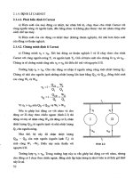
statistical symbols. These latter symbols are defined in Section 1.11. The lamina/laminate coordinate
axes used for all properties and a summary of the mechanical property notation are shown in Figure
1.1.6.1.
•
The symbols f and m, when used as either subscripts or superscripts, always denote fiber and
matrix, respectively.
•
The type of stress (for example, cy - compression yield) is always used in the superscript position.
•
Direction indicators (for example, x, y, z, 1, 2, 3, and so on) are always used in the subscript posi-
tion.
•
Ordinal indicators of laminae sequence (for example, 1, 2, 3, and so on) are used in the super-
script position and must be parenthesized to distinguish them from mathematical exponents.
MIL-HDBK-17-4
9
FIGURE 1.1.6.1
Mechanical property notation.
MIL-HDBK-17-4
:
•
Other indicators may be used in either subscript or superscript position, as appropriate for clarity.
•
Compound symbols (such as, basic symbols plus indicators) which deviate from these rules are
shown in their specific form in the following list.
The following general symbols and abbreviations are considered standard for use in MIL-HDBK-17.
Where exceptions are made, they are noted in the text and tables.
A - (1) area (m
2
,in
2
)
- (2) ratio of alternating stress to mean stress
- (3) A-basis for mechanical property values
Ann - Annealed
a - (1) length dimension (mm,in)
- (2) acceleration (m/sec
2
,ft/sec
2
)
- (3) amplitude
- (4) crack or flaw dimension (mm, in.)
a
c
- critical half crack length
a
o
- initial half crack length
B - (1) B-basis for mechanical property values
- (2) biaxial ratio
Btu - British thermal unit(s)
BUS - individual or typical bearing ultimate strength
BYS - individual or typical bearing yield strength
b - (1) width dimension (mm, in.), for example, the width of a bearing or compression panel nor-
mal to load,
or breadth of beam cross-section
- (2) width of sections; subscript “bending”
br - subscript “bearing”
C - (1) specific heat (kJ/kg °C, Btu/lb °F)
- (2) Celsius
CC - center cracked
CEM - consumable electrode melted
CF - centrifugal force (N, lbf)
CPF - crossply factor
CG - (1) center of mass, "center of gravity"
- (2) area or volume centroid
C
L
- centerline
CT - compact tension
c - column buckling end-fixity coefficient
cpm - cycles per minute
D - (1) diameter (mm, in.)
- (2) hole or fastener diameter (mm, in.)
- (3) plate stiffness (N-m, lbf-in)
d - mathematical operator denoting differential
E - modulus of elasticity in tension, average ratio of stress to strain for stress below proportional
limit (GPa, Msi)
E
c
- modulus of elasticity in compression, average ratio of stress to strain for stress below
proportional limit (GPa, Msi)
c
’
E
- modulus of elasticity of honeycomb core normal to sandwich plane (GPa, Msi)
E
sec
- secant modulus (GPa, Msi)
E
tan
- tangent modulus (GPa, Msi)
ELI - extra low interstitial (grade of titanium alloy)
ER - equivalent round
ESR - electro-slag remelted
MIL-HDBK-17-4
;
e - (1) minimum distance from a hole center to the edge of the sheet (mm, in.)
-
(2) elongation in percent, a measure of the ductility of a material based on a tension test
-
(3) unit deformation or strain
-
(4) subscript “fatigue or endurance”
e/D - ratio of edge distance to hole diameter (bearing strength)
F - (1) stress (MPa, ksi)
- (2) Fahrenheit
F
b
- bending stress (MPa, ksi)
F
ccr
- crushing or crippling stress (upper limit of column stress for failure) (MPa, ksi)
F
pl
- proportional limit (MPa, ksi)
F
su
- ultimate stress in pure shear (this value represents the average shear stress over the
cross-section) (MPa, ksi)
F
tu
- ultimate stress in tension (MPa, ksi)
FV - fiber volume (%)
f - (1) internal (or calculated) stress (MPa, ksi)
- (2) stress applied to the gross flawed section (MPa, ksi)
- (3) creep stress (MPa, ksi)
f
c
- internal (or calculated) compressive stress (MPa, ksi)
f
c
- (1) maximum stress at fracture (MPa, ksi)
- (2) gross stress limit (for screening elastic fracture data (MPa, ksi)
ft - foot, feet
G - modulus of rigidity (shear modulus) (GPa, Msi)
GPa - gigapascal(s)
g - (1) gram(s)
- (2) acceleration due to gravity (m/s
2
, ft/s
2
)
H/C - honeycomb (sandwich)
h - height dimension (mm, in.) for example, the height of a beam cross-section
hr - hour(s)
I - area moment of inertia (mm
4
, in.
4
)
i - slope (due to bending) of neutral plane in a beam, in radians
in. - inch(es)
J - (1) torsion constant (= I
p
for round tubes) (m
4
, in.
4
)
- (2) Joule
K - (1) Kelvin
- (2) stress intensity factor (MPa2m, ksi2in.)
- (3) coefficient of thermal conductivity (W/m °C, Btu/ft
2
/hr/in./°F)
- (4) correction factor
- (5) dielectric constant
K
app
- apparent plane strain fracture toughness or residual strength (MPa2m, ksi2in.)
K
c
- critical plane strain fracture toughness, a measure of fracture toughness at point of crack
growth instability (MPa2m, ksi2in.)
K
Ic
- plane strain fracture toughness (MPa2m, ksi2in.)
K
N
- empirically calculated fatigue notch factor
K
s
- plate or cylinder shear buckling coefficient
K
t
- (1) theoretical elastic stress concentration factor
- (2) t
w
/c ratio in H/C sandwich
Kv - dielectric strength (KV/mm, V/mil)
K
x
,K
y
- plate or cylinder compression buckling coefficient
k - strain at unit stress (m/m, in./in.)
ksi - kips (1,000 pounds) per square inch
L - cylinder, beam, or column length (mm, in.)
L' - effective column length (mm, in.)
LT - long transverse (grain direction)
MIL-HDBK-17-4
32
lb. - pound
"
o
- gage length
M - applied moment or couple (N-m, in lbf)
Mg - megagram(s)
MIG - metal-inert-gas (welding)
MPa - megapascal(s)
MS - military standard
M.S. - margin of safety
MW - molecular weight
MWD - molecular weight distribution
m - (1) mass (kg, lb.)
- (2) number of half wave lengths
- (3) metre
- (4) slope
mm - millimetre(s)
N - (1) number of fatigue cycles to failure
- (2) number of laminae in a laminate
- (3) distributed in-plane forces on a panel (lbf/in.)
- (4) Newton
- (5) normalized
NA - neutral axis
n - (1) number of times in a set
- (2) number of half or total wavelengths
- (3) number of fatigue cycles endured
- (4) subscript “normal”;
- (5)cycles applied to failure
- (6) shape parameter for the standard stress-strain curve (Ramberg-Osgood parameter)
P - (1) applied load (N, lbf)
- (2) exposure parameter
- (3) probability
- (4) specific resistance (Ω)
P
u
- test ultimate load, (N, lb. per fastener)
P
y
- test yield load, (N, lb per fastener)
p - normal pressure (Pa, psi)
psi - pounds per square inch
Q - area static moment of a cross-section (mm
3
, in.
3
)
Q&T - quenched and tempered
q - shear flow (N/m, lbf/in.)
R - (1) algebraic ratio of minimum load to maximum load in cyclic loading
- (2) reduced ratio
RA - reduction of area
R.H. - relative humidity
RMS - root-mean-square
RT - room temperature
r - (1) radius (mm, in.)
- (2) root radius (mm, in.)
- (3) reduced ratio (regression analysis)
S - (1) shear force (N, lbf)
- (2) nominal stress in fatigue (MPa, ksi)
- (3) S-basis for mechanical property values
S
a
- stress amplitude in fatigue (MPa, ksi)
S
e
- fatigue limit (MPa, ksi)
S
m
- mean stress in fatigue (MPa, ksi)
S
max
- highest algebraic value of stress in the stress cycle (MPa, ksi)
S
min
- lowest algebraic value of stress in the stress cycle (MPa, ksi)
MIL-HDBK-17-4
33
S
R
- algebraic difference between the minimum and maximum stresses in one cycle (MPa, ksi)
S.F. - safety factor
SCC - stress-corrosion cracking
ST - short transverse (grain direction)
STA - solution treated and aged
S-N - stress vs. fatigue life
s - (1) arc length (mm, in.)
- (2) H/C sandwich cell size (mm, in.)
T - (1) temperature (°C, °F)
- (2) applied torsional moment (N-m, in lbf)
TIG - tungsten-inert-gas (welding)
T
F
- exposure temperature
T
F
- exposure temperature (°C, °F)
T
m
- melting temperature (°C, °F)
t - (1) thickness (mm, in.)
- (2) exposure time (s)
- (3) elapsed time (s)
V - (1) volume (mm
3
, in.
3
)
- (2) shear force (N, lbf)
W - (1) weight (N, lbf)
- (2) width (mm, in.)
- (3) Watt
x - distance along a coordinate axis
Y - nondimensional factor relating component geometry and flaw size
y - (1) deflection (due to bending) of elastic curve of a beam (mm, in.)
- (2) distance from neutral axis to given point
- (3) distance along a coordinate axis
Z - section modulus, I/y (mm
3
, in.
3
)
z - distance along a coordinate axis
α
- coefficient of thermal expansion (m/m/°C, in./in./°F)
γ
- shear strain (m/m, in./in.)
∆ - difference (used as prefix to quantitative symbols)
Φ - angular deflection
δ - elongation or deflection (mm, in.)
ε - strain (m/m, in./in.)
ε
e
- elastic strain (m/m, in./in.)
ε
p
- plastic strain (m/m, in./in.)
µ - permeability
η - plasticity reduction factor
ν
- Poisson's ratio
ρ - (1) density (g/cm
3
, lb/in.
3
)
- (2) radius of gyration (mm, in.)
- (3) radius of gyration; Neuber constant (block length)
′
ρ
c
- H/C sandwich core density (kg/m
3
, lb/in.
3
)
Σ - total, summation
σ - standard deviation
σ
ij
,
τ
ij
- stress in j direction on surface whose outer normal is in i direction (i, j = 1, 2, 3 or x, y, z)
(MPa, ksi)
Τ - applied shear stress (MPa, ksi)
ω - angular velocity (radians/s)
∞
- infinity
MIL-HDBK-17-4
34
1.1.6.1.1
Constituent properties
The following symbols apply specifically to the constituent properties of a typical composite material.
E
f
- Young's modulus of fiber (MPa, ksi)
E
m
- Young's modulus of matrix material (MPa, ksi)
E
R
- Young’s modulus of reinforcement (MPa, ksi)
G
f
- shear modulus of fiber (MPa, ksi)
G
m
- shear modulus of matrix (MPa, ksi)
G
R
- shear modulus of reinforcement (MPa, ksi)
′
G
cx
- shear modulus of sandwich core along X-axis (MPa, ksi)
′
G
cy
- shear modulus of sandwich core along Y-axis (MPa, ksi)
"
- fiber length (mm, in.)
α
f
- coefficient of thermal expansion for fiber material (m/m/°C, in./in./°F)
α
m
- coefficient of thermal expansion for matrix material (m/m/°C, in./in./°F)
ν
f
- Poisson's ratio of fiber material
ν
m
- Poisson's ratio of matrix material
σ - applied axial stress at a point, as used in micromechanics analysis (MPa, ksi)
τ
- applied shear stress at a point, as used in micromechanics analysis (MPa, ksi)
1.1.6.1.2
Laminae and laminates
The following symbols, abbreviations, and notations apply to composite laminae and laminates.
A
ij
(i,j = 1,2,6) - extensional rigidities (N/m, lbf/in.)
B
ij
(i,j = 1,2,6) - coupling matrix (N, lbf)
C
ij
(i,j = 1,2,6) - elements of stiffness matrix (Pa, psi)
D
x
, D
y
- flexural rigidities (N-m, lbf-in.)
D
xy
- twisting rigidity (N-m, lbf-in.)
D
ij
(i,j = 1,2,6) - flexural rigidities (N-m, lbf-in.)
E
1
- Young's modulus of lamina parallel to fiber or warp direction (GPa, Msi)
E
2
- Young's modulus of lamina transverse to fiber or warp direction (GPa, Msi)
E
x
- Young's modulus of laminate along x reference axis (GPa, Msi)
E
y
- Young's modulus of laminate along y reference axis (GPa, Msi)
G
12
- shear modulus of lamina in 12 plane (GPa, Msi)
G
xy
- shear modulus of laminate in xy reference plane (GPa, Msi)
h
i
- thickness of i
th
ply or lamina (mm, in.)
M
x
, M
y
, M
xy
- bending and twisting moment components (N-m/m, in lbf/in. in plate and shell analysis)
n
f
- number of fibers per unit length per lamina
Q
x
, Q
y
- shear force parallel to z axis of sections of a plate perpendicular to x and y axes,
respectively (N/m, lbf/in.)
Q
ij
(i,j = 1,2,6) - reduced stiffness matrix (Pa, psi)
u
x
, u
y
, u
z
- components of the displacement vector (mm, in.)
x
o
y
o
z
o
u
,
u
,
u
- components of the displacement vector at the laminate's midsurface (mm, in.)
V
v
- void content (% by volume)
V
f
- fiber content or fiber volume (% by volume)
V
m
- matrix content (% by volume)
V
x
, V
y
- edge or support shear force (N/m, lbf/in.)
W
f
- fiber content (% by weight)
W
m
- matrix content (% by weight)
W
s
- weight of laminate per unit surface area (N/m
2
, lbf/in.
2
)
α
1
- lamina coefficient of thermal expansion along 1 axis (m/m/°C, in./in./°F)
α
2
- lamina coefficient of thermal expansion along 2 axis (m/m/°C, in./in./°F)
MIL-HDBK-17-4
35
α
x
- laminate coefficient of thermal expansion along general reference x axis
(m/m/°C, in./in./°F)
α
y
- laminate coefficient of thermal expansion along general reference y axis
(m/m/°C, in./in./°F)
α
xy
- laminate shear distortion coefficient of thermal expansion (m/m/°C, in./in./°F)
θ - angular orientation of a lamina in a laminate, that is, angle between 1 and x axes (°)
λ
xy
- product of
ν
xy
and
ν
yx
ν
12
- Poisson's ratio relating contraction in the 2 direction as a result of extension in the 1
direction
3
ν
21
- Poisson's ratio relating contraction in the 1 direction as a result of extension in the 2
direction
1
ν
xy
- Poisson's ratio relating contraction in the y direction as a result of extension in the x
direction
1
ν
yx
- Poisson's ratio relating contraction in the x direction as a result of extension in the y
direction
1
ρ
c
- (1) density of a single lamina (g/cm
3
, lb/in.
3
)
- (2) density of a laminate (g/cm
3
, lb/in.
3
)
φ - (1) general angular coordinate, (°)
- (2) angle between x and load axes in off-axis loading (°)
1.1.6.1.3
Subscripts
The following subscript notations are considered standard in MIL-HDBK-17.
1, 2, 3 - laminae natural orthogonal coordinates (1 is fiber)
A - axial
a - (1) adhesive
- (2) alternating
app - apparent
byp - bypass
c - (1) composite system, specific fiber/matrix composition.
- (2) critical
- (3) compression
cf - centrifugal force
e - fatigue or endurance
eff - effective
eq - equivalent
f - fiber
H - hoop
i - i
th
position in a sequence
L - lateral
m - (1) matrix
- (2) mean
max - maximum
min - minimum
n - (1) n
th
(last) position in a sequence
- (2) normal
p - polar
s - symmetric
st - stiffener
T - transverse
3
The convention for Poisson
’
s ratio should be checked before comparing different sources as different conventions are used.
MIL-HDBK-17-4
36
t - value of parameter at time t
x, y, z - general coordinate system
∑ - total, or summation
o - initial or reference datum
( ) - format for indicating specific, temperature associated with term in parentheses. RT - room
temperature (21°C, 70°F); all other temperatures in °F unless specified.
1.1.6.1.4
Superscripts
The following superscript notations are considered standard in MIL-HDBK-17.
b - bending
br - bearing
c - (1) compression
- (2) creep
cc - compression crippling
cr - compression buckling
e - elastic
f - fiber
(i) - i
th
ply or lamina
lim - limit, used to indicate limit loading
m - matrix
ohc - open hole compression
oht - open hole tension
p - plastic
pl - proportional limit
rup - rupture
s - shear
scr - shear buckling
sec - secant (modulus)
so - offset shear
T - temperature or thermal
t - tension
tan - tangent (modulus)
u - ultimate
y - yield
' - secondary (modulus), or denotes properties of H/C core when used with subscript c
1.1.6.1.5
Acronyms
The following acronyms are used in MIL-HDBK-17.
AISI - American Iron and Steel Institute
AMS - Aerospace Materials Specification
ANOVA - analysis of variance
ARL - U.S. Army Research Laboratory
ASTM - American Society for Testing and Materials
CTA - cold temperature ambient
CTD - cold temperature dry
CTE - coefficient of thermal expansion
CV - coefficient of variation
CVD - chemical vapor deposition
DCB - double cantilever beam
DLL - design limit load
DoD - Department of Defense
MIL-HDBK-17-4
37
EDM - electric discharge machining
ENF - end notched flexure
ETW - elevated temperature wet
FAA - Federal Aviation Administration
IITRI - Illinois Institute of Technology Research Institute
LPT - laminate plate theory
LSS - laminate stacking sequence
MMB - mixed mode bending
MMC - metal matrix composite
NAS - National Aerospace Standard
NASA - National Aeronautics and Space Administration
NDI - nondestructive inspection
RH - relative humidity
RT - room temperature
RTA - room temperature ambient
RTD - room temperature dry
SAE - Society of Automotive Engineers
SEM - scanning electron microscopy
SI - International System of Units (Le Système Interational d'Unités)
TEM - transmission electron microscopy
TMC - titanium matrix composite
VNB - V-notched beam
1.1.6.2
Material system codes
The materials systems codes which are used in the handbook consist of a fiber system code and a
matrix material code separated by a virgule (/), for example, AIO/Al for alumina reinforced aluminum. The
codes for the fiber and matrix materials appear in Table 1.1.6.2(a) and (b).
TABLE 1.1.6.2(a)
Fiber system codes
. TABLE 1.1.6.2(b)
Matrix material codes.
AlO Alumina Al Aluminum
B Boron Cu Copper
BC Boron carbide Mg Magnesium
C Carbon Ti Titanium
Gr Graphite
SiC Silicon Carbide
Fe Steel
W Tungsten
MIL-HDBK-17-4
38
1.1.6.3
System of units
To comply with Department of Defense Instructive 5000.2, Part 6, Section M, "Use of the Metric Sys-
tem," dated February 23, 1991, the data in MIL-HDBK-17 are generally presented in both the International
System of Units (SI units) and the U. S. Customary (English) system of units. ASTM E380, Standard for
Metric Practice, provides guidance for the application for SI units which are intended as a basis for world-
wide standardization of measurement units (Reference 1.1.6.3(a)). Further guidelines on the use of the SI
system of units and conversion factors are contained in the following publications (References 1.1.6.3(b)
through 1.1.6.3(f)):
(1)
DARCOM P 706-470, “Engineering Design Handbook: Metric Conversion Guide”, July 1976.
(2)
NBS Special Publication 330, "The International System of Units (SI)”, National Bureau of Stan-
dards, 1986 edition.
(3)
NBS Letter Circular LC 1035, "Units and Systems of Weights and Measures, Their Origin, Devel-
opment, and Present Status”, National Bureau of Standards, November 1985.
(4)
NASA Special Publication 7012, "The International System of Units Physical Constants and Con-
version Factors", 1964.
(5)
IEEE SI 10, “International System of Units (SI): The Modern Metric System”, Institute of Electrical
and Electronic Engineers (IEEE), November 1997.
English to SI conversion factors pertinent to MIL-HDBK-17 data are contained in Table 1.1.6.3.
MIL-HDBK-17-4
39
TABLE 1.1.6.3
English to SI conversion factors.
To convert from to Multiple by*
Btu (thermochemical)/in.
2
-s watt/meter
2
(W/m
2
) 1.634 246 E+06
Btu-in/(s-ft
2
-°F) W/(m K) 5.192 204 E+02
Btu/lb F Joule/gram-Kelvin 4.1868**
(or Btu#lb.
-1
#F
-1
)(J/g#K) or J#g
-1
#K
-1
)
Btu/[(hr)(ft
2
)(F)/ft] Watt/metre-Kelvin 1.7307
(or Btu#hr
-1
#ft
-2
#F
-1
#ft) W/(m#K) or W#m
-1
#K
-1
)
degree Fahrenheit degree Celsius (°C) T = (T - 32)/1.8
degree Fahrenheit kelvin (K) T = (T + 459.67)/1.8
foot meter (m) 3.048 000 E-01
ft
2
m
2
9.290 304 E-02
foot/second meter/second (m/s) 3.048 000 E-01
ft/s
2
m/s
2
3.048 000 E-01
inch meter (m) 2.540 000 E-02
in.
2
meter
2
(m
2
) 6.451 600 E-04
in.
3
m
3
1.638 706 E-05
in./in./F Metre/metre/Kelvin 1.8
(or in.#in.
-1
#F
-1
)m/(m#K) or (m#m
-1
#K#
-1
)
kilogram-force (kgf) newton (N) 9.806 650 E+00
kgf/m
2
pascal (Pa) 9.806 650 E+00
kip (1000 lbf) newton (N) 4.448 222 E+03
ksi (kip/in.
2
) MPa 6.894 757 E+00
ksi√in. megapascal √meter 1.0989
(MPa#m 1/2)***
lbf-in. N-m 1.129 848 E-01
lbf-ft N-m 1.355 818 E+00
lbf/in.
2
(psi) pascal (Pa) 6.894 757 E+03
lb./in.
2
gm/m
2
7.030 696 E+05
lb./in.
3
kg/m
3
2.767 990 E+04
Msi (10
6
psi) GPa 6.894 757 E+00
pound-force (lbf) newton (N) 4.488 222 E+00
pound-mass (lb. avoirdupois) kilogram (kg) 4.535 924 E-01
torr pascal (Pa) 1.333 22 E+02
*The letter “E” following the conversion factor stands for exponent and the two digits
after the letter “E” indicate the power of 10 by which the number is to be multiplied.
**One Pascal (Pa) = one newton/metre
2
.
***Conversion factor is exact.
MIL-HDBK-17-4
3:
1.1.7
DEFINITIONS
The following definitions are used within MIL-HDBK-17. This glossary of terms is not totally compre-
hensive but it does represent nearly all commonly used terms. Where exceptions are made, they are
noted in the text and tables. For ease of identification the definitions have been organized alphabetically.
A-Basis (or A-Value) A statistically-based material property; a 95% lower confidence bound on the
first percentile of a specified population of measurements. Also a 95% lower tolerance bound for the up-
per 99% of a specified population.
Accuracy The degree of conformity of a measured or calculated value to some recognized stan-
dard or specified value. Accuracy involves the systematic error of an operation.
ADK Notation used for the k-sample Anderson-Darling statistic, which is used to test the hypothesis
that k batches have the same distribution.
Aging The effect, on materials, of exposure to an environment for a period of time; the process of
exposing materials to an environment for an interval of time.
Ambient The surrounding environmental conditions such as pressure or temperature.
Angleply Lamina orientation not coinciding with load axis.
Anisotropic Not isotropic; having mechanical and/or physical properties which vary with direction
relative to natural reference axes inherent in the material.
Aspect Ratio In an essentially two-dimensional rectangular structure (for example, a panel), the
ratio of the long dimension to the short dimension. However, in compression loading, it is sometimes con-
sidered to be the ratio of the load direction dimension to the transverse dimension. Also, in fiber micro-
mechanics, it is referred to as the ratio of length to diameter.
B-Basis (or B-Value) A statistically-based material property; a 95% lower confidence bound on the
tenth percentile of a specified population of measurements. Also a 95% lower tolerance bound for the up-
per 90% of a specified population. (See Volume 1, Section 8.1.4)
Balanced Laminate A composite laminate in which all laminae at angles other than 0 degrees and
90 degrees occur only in ± pairs (not necessarily adjacent).
Bearing Area The product of the pin diameter and the specimen thickness.
Bearing Load A compressive load on an interface.
Bearing Yield Strength The bearing stress at which a material exhibits a specified limiting deviation
from the proportionality of bearing stress to bearing strain.
Bend Test A test of ductility by bending or folding, usually with steadily applied forces. In some in-
stances the test may involve blows to a specimen having a cross section that is essentially uniform over a
length several times as great as the largest dimension of the cross section.
Binomial Random Variable The number of successes in independent trials where the probability of
success is the same for each trial.
MIL-HDBK-17-4
3;
Buckling (Composite) A mode of structural response characterized by an out-of-plane material
deflection due to compressive action on the structural element involved. In advanced composites, buckling
may take the form not only of conventional general instability and local instability but also a micro-instability
of individual fibers.
Bundle A general term for a collection of essentially parallel fibers or fibers.
Censoring Data is right (left) censored at M, if, whenever an observation is less than or equal to M
(greater than or equal to M), the actual value of the observation is recorded. If the observation exceeds (is
less than) M, the observation is recorded as M.
Coefficient of Linear Thermal Expansion The change in length per unit length resulting from a
one-degree rise in temperature.
Coefficient of Variation The ratio of the population (or sample) standard deviation to the population
(or sample) mean.
Collimated Rendered parallel.
Composite Class As used in the handbook, a major subdivision of composite construction in which
the class is defined by the fiber system and the matrix class, for example, organic-matrix filamentary lami-
nate.
Composite Material Composites are considered to be combinations of materials differing in com-
position or form on a macroscale. The constituents retain their identities in the composite; that is, they do
not dissolve or otherwise merge completely into each other although they act in concert. Normally, the
components can be physically identified and exhibit an interface between one another.
Confidence Coefficient See Confidence Interval.
Confidence Interval A confidence interval is defined by a statement of one of the following forms:
where 1-
α
is called the confidence coefficient. A statement of type (1) or (2) is called a one-sided confi-
dence interval and a statement of type (3) is called a two-sided confidence interval. In (1) a is a lower con-
fidence limit and in (2) b is an upper confidence limit. With probability at least 1-
α
, the confidence interval
will contain the parameter θ.
Constituent In general, an element of a larger grouping. In advanced composites, the principal
constituents are the fibers and the matrix.
Continuous fiber A yarn or strand in which the individual fibers are substantially the same length
as the strand.
Continuous Fiber - A fiber which spans the dimension of the test specimen.
Creep The time dependent part of strain resulting from an applied stress.
Creep, Rate Of The slope of the creep-time curve at a given time.
()
αθ
−≤<
1}{1
aP
()
αθ
−≤<
1}{2
bP
()
αθ
−≤<<
1}{3
baP
MIL-HDBK-17-4
42
Critical Value(s) When testing a one-sided statistical hypothesis, a critical value is the value such
that, if the test statistic is greater than (less than) the critical value, the hypothesis is rejected. When test-
ing a two-sided statistical hypothesis, two critical values are determined. If the test statistic is either less
than the smaller critical value or greater than the larger critical value, then the hypothesis is rejected. In
both cases, the critical value chosen depends on the desired risk (often 0.05) of rejecting the hypothesis
when it is true.
Crossply Any filamentary laminate which is not uniaxial. Same as Angleply. In some references,
the term crossply is used to designate only those laminates in which the laminae are at right angles to one
another, while the term angleply is used for all others.
Cumulative Distribution Function See Volume 1, Section 8.1.4.
Debond A deliberate separation of a bonded joint or interface, usually for repair or rework pur-
poses. Any separation of an interface between constituents in a composite.
Deformation The change in shape of a specimen caused by the application of a load or force.
Degradation A deleterious change in chemical structure, physical properties or appearance.
Delamination The separation of the layers of material in a laminate. This may be local or may
cover a large area of the laminate. It may occur at any time in the cure or subsequent life of the laminate
and may arise from a wide variety of causes.
Denier A direct numbering system for expressing linear density, equal to the mass in grams per
9000 meters of yarn, fiber, fiber, or other textile strand.
Density The mass per unit volume.
Deviation Variation from a specified dimension or requirement, usually defining the upper and
lower limits.
Distribution A formula which gives the probability that a value will fall within prescribed limits. (See
Normal, Weibull, and Lognormal Distributions, also Volume 1, Section 8.1.4).
Dry a material condition of moisture equilibrium with a surrounding environment at 5% or lower rela-
tive humidity.
Ductility The ability of a material to deform plastically before fracturing.
Elasticity The property of a material which allows it to recover its original size and shape immedi-
ately after removal of the force causing deformation.
Elongation The increase in gage length or extension of a specimen during a tension test, usually
expressed as a percentage of the original gage length.
End A single fiber, strand, roving or yarn being or already incorporated into a product. An end may
be an individual warp yarn or cord in a woven fabric. In referring to aramid and glass fibers, an end is
usually an untwisted bundle of continuous fibers.
Extensometer A device for measuring linear strain.
F-Distribution See Volume 1, Section 8.1.4.