Foseco Non-Ferrous Foundryman’s Handbook Part 15 potx
Bạn đang xem bản rút gọn của tài liệu. Xem và tải ngay bản đầy đủ của tài liệu tại đây (536.47 KB, 20 trang )
268 Foseco Non-Ferrous Foundryman’s Handbook
than the pouring temperature). Read expansion or shrinkage (S)
expressed as a percentage on the horizontal axis.
(c) Mould wall movement (M%) depends on the hardness of the mould and
can vary from zero for hard silicate or resin moulds to 2% for green sand
moulds with a mould hardness of 85° (B scale). Add the mould wall
movement from the expansion to give a final value of S. If this is positive
or zero the casting will not need feeding.
(d) The weight of metal in the feeder under consideration (W
F
). The total
weight of casting (W
C
) which can be fed from a feeder of weight W
F
is
W
C
= C/100 ϫ 100/S ϫ W
F
(11)
If the total weight of casting section (W
t
) which requires feeding is
greater than W
C
then increase the dimensions of the feeder until:
W
T
= W
C
i.e. W
F
= W
T
ϫ 100/C ϫ S/100 (12)
4. Calculate the dimensions of the feeder neck
(a) Top feeders
No calculation of feeder-neck dimensions are required. If possible feeder
sleeves should be used with breaker cores.
(b) Side feeders
The required feeder-neck dimensions are obtained from the calculation
of the neck modulus (M
N
) by applying the ratios:
M
C
:M
N
:M
F
= 1.0:1.1 ͱST/100:1.2ͱST/100
then using either the endless bar equation (Fig. 17.5 g) or the diagram in
Fig. 17.6.
Foseco feeding systems
Introduction
Foseco provides complete feeding systems for foundries, comprising:
Sleeves – insulating and exothermic for all metals
Breaker cores – to aid removal of the feeder from the casting
Application technology – to suit the particular moulds and moulding
machine used
Aids to the calculation of feeder requirements
Feeding systems 269
Range of feeder products
The Foseco range of products comprises:
Product
name
Type Application
casting alloy
Remarks
KALMIN S Insulating Al, Cu base
iron, steel
extend solidification time by
2.0–2.2
KALMINEX
2000
Insulating and
exothermic
iron, steel extend solidification time by
2.5–2.7
FEEDEX HD Highly
exothermic
iron, steel small riser-to-casting contact
area use where application
area is limited
KALMINEX Insulating and
exothermic
iron, steel for large diameter feeders
KALBORD Insulating iron, steel
copper base
in form of jointed mats for
large feeders
KALPAD Insulating iron, steel
copper base
prefabricated boards or
shapes
KAPEX Insulating Al, Cu base
iron, steel
prefabricated feeder lids,
replace hot-topping
compounds
KALMIN S, KALMINEX 2000, FEEDEX HD and KALMINEX products are
supplied as prefabricated sleeves in a wide range of sizes and shapes, with
or without breaker cores.
KALMIN S feeder sleeves
By using a high proportion of light refractory raw materials, a density of
0.45 g/cm
3
is achieved, ensuring highly insulating properties. KALMIN S
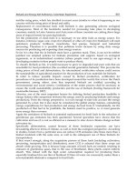
Figure 17.8 Foseco sleeve types.
270 Foseco Non-Ferrous Foundryman’s Handbook
Figure 17.9 Example of sleeve support on a moulding machine pattern plate.
Figure 17.10 An insertable KALMINEX sleeve with breaker core attached and a
typical sleeve pattern.
Figure 17.11 The KALSERT system in operation. KALMINEX sleeves being
inserted into green sand moulds on an automatic moulding line.
Feeding systems 271
sleeves are particularly suitable for aluminium, copper-base and iron alloy
sand castings since the raw materials used are neutral to both the casting
alloys and to the moulding sand. KALMIN S sleeves are supplied as
“parallel conical”, “opposite conical”, or cylindrical sleeves for either ram-
up application or insertion into cope or drag, Figs 17.8, 17.9, 17.10 and
17.11. They can be applied in the following moulding systems:
Moulding method KALMIN S feeder sleeve type
Insert sleeves into the turned-over
cope mould especially in automatic
moulding lines
Parallel conical insert sleeves
in conjunction with Foseco
Sleeve Patterns
Insertion of the feeder sleeve from
the top of the cope mould into the
cavity created by means of a suitable
sleeve pattern which is drawn after
moulding
Opposite conical sleeve
Ram-up on the pattern plate in a
machine moulding or a
hand-moulding operation
Parallel conical insert feeder
sleeve, opposite conical feeder
sleeve or cylindrical sleeve
Insert sleeve in a vertically parted
moulding system
Parallel conical insert and/or
opposite conical feeder sleeve
Insert sleeves into shell moulds Parallel conical insert and/or
opposite conical feeder sleeve
Application of feeder sleeves in a
drag mould over a feeder base or
bridge core
Parallel conical feeder sleeve
as floating sleeve system
KALMIN S feeder sleeves extend the solidification times by a factor of
2.0–2.2 compared to natural sand feeders of the same size. From these
results, Modulus Extension Factors (MEFs) of 1.4–1.5 have been calcu-
lated. Though KALMIN S feeder sleeves can give more than 33% of their
feeder volume to the solidifying casting, it is recommended that a
maximum of one-third of the feed metal volume should be fed into the
casting so that the residual feeder modulus is adequate in relation to the
casting modulus at the end of solidification. For this reason, it is
recommended to consider modulus as well as solidification shrinkage in
order to determine the correct feeder. Foseco provides tables allowing
KALMIN S feeders to be selected with the desired modulus, volume
(capacity) and dimensions.
272 Foseco Non-Ferrous Foundryman’s Handbook
KALMINEX 2000 feeder sleeves
KALMINEX 2000 is a highly insulating and exothermic feeder sleeve
material in the form of prefabricated sleeves for iron and steel casting in the
modulus range between 1.0 and 3.2 cm. For light and other non-ferrous
alloys the KALMINEX 2000 feeder sleeve material is not recommended. The
manufacturing process specifically developed for this unique feeder sleeve
material not only ensures a low density of 0.59 g/cm and, therefore, a high
grade of insulation but also an additional exothermic reaction peaking at
1600°C. Due to the strength of the KALMINEX 2000 feeder sleeves, they can
often be rammed up directly on the pattern plate on many moulding
machines.
KALMINEX 2000 feeder sleeves can be applied in the following moulding
systems:
Application method KALMINEX 2000 feeder shape
Insert sleeves into the turned-over
cope mould especially in
automatic moulding lines
Parallel conical insert sleeves in
conjunction with FOSECO Sleeve
Patterns
Ram-up on the pattern plate in a
machine moulding or a
hand-moulding system
Parallel conical insert feeder sleeve,
opposite conical feeder sleeve or
cylindrical sleeve
Insert sleeve in a vertically parted
moulding system
Parallel conical insert and/or
opposite conical feeder sleeve
Insert sleeve into shell moulds Parallel conical insert and/or
opposite conical feeder sleeve
Application of feeder sleeves in a
drag mould over a feeder base or
on a bridge core
Parallel conical feeder sleeve as
floating sleeve system
When determining the solidification times with KALMINEX 2000 feeder
sleeves it has been found that they extend the solidification time by a factor
of 2.5–2.7 compared to a natural sand feeder of the same size. From these
results Modulus Extension Factors (MEFs) have been calculated between
1.58 and 1.64. Foseco provides tables allowing KALMINEX 2000 feeders to
be selected with the desired modulus, volume (capacity) and dimensions.
Under specific practical conditions it has been found that the KALMINEX
2000 feeder sleeves can render 64% of their volume to the solidifying casting.
When using feeders with the correct modulus it is necessary to take into
account that the modulus of the residual feeder – if more than 33% of the
feeder volume is fed into the casting – may not be adequate in relation to the
Feeding systems 273
casting modulus towards the end of the solidification. Therefore, it is
essential to calculate shrinkage as well as modulus in order to determine the
correct feeder sleeve.
FEEDEX HD V-sleeves
FEEDEX HD V feeder sleeves are used for iron and steel casting alloys.
FEEDEX HD is a fast-igniting, highly exothermic and pressure-resistant
feeder sleeve material. The sleeves possess a small feeder volume, a massive
wall, but only a small riser-to-casting contact area, Fig. 17.12. They are,
therefore, specially suited for use for “spot feeding” on casting sections
which have a limited feeder sleeve application area. The sleeves are located
onto the pattern plate using special locating pins, the majority are supplied
with shell-moulded breaker cores. Owing to their small aperture, these
breaker cores are not recommended for steel casting.
FEEDEX HD V-sleeves are particularly useful for ductile iron castings since
with their low volume shrinkage of below 3%, a modulus-controlled
KALMIN or KALMINEX 2000 feeder will often have more liquid metal than
is necessary. The very high modulus and relatively low volume of FEEDEX
HDV gives improved yield. In many ductile iron applications, the small
breaker core aperture of the feeder means that the feeder is separated from the
casting during the shakeout operation and the cleaning cost is reduced.
Figure 17.12 FEEDEX HD V-sleeve.
274 Foseco Non-Ferrous Foundryman’s Handbook
Figure 17.13 The application of FEEDEX HD V-sleeves to ductile iron castings.
Feeding systems 275
When used in ductile iron applications, it is important to note that the
high temperature reached in the highly exothermic feeder can cause residual
magnesium in the iron to be oxidised so that there may be a danger of
denodularisation on the casting–feeder interface. To avoid this, residual Mg
should be greater than 0.045%, inoculation practice should be optimised and
thick breaker cores used. Note that when calculating FEEDEX metal volume,
only 50% of the capacity should be assumed since part of the metal in the
feeder will be lamellar due to oxidation of the Mg in the feeder cavity.
Figure 17.13 shows examples of the use of FEEDEX HD V-sleeves on
ductile iron castings.
KALMINEX feeder sleeves
KALMINEX exothermic-insulating feeder sleeves are used for all iron and
steel casting alloys. They are supplied with feeder diameters from 80 to
850 mm for the modulus range between 2.4 and 22.0 cm and are suitable for
larger-sized castings.
The manufacturing process specifically developed for this exothermic-
insulating product and the selection of specific raw materials give a total
closed pore volume of nearly 50%. The excellent heat insulation resulting
from the low density (compared with moulding sand) is enhanced by an
exothermic reaction.
When determining the solidification times with KALMINEX feeder
sleeves it has been found that they extend the solidification time by a factor
of 2.0–2.4 compared to the natural sand feeders of the same size. From these
results Modulus Extension Factors (MEFs) of 1.4–1.55 have been found.
Under practical conditions it has been found that KALMINEX feeders when
adequately covered with KAPEX lids or a suitable APC (anti-piping
compound) may render up to 64% of their contents into the casting. When
using feeders with the correct modulus it is necessary to take into account
that the modulus of the residual feeder – if more than 33% of the feeder
volume is fed into the casting – may not be adequate in relation to the
casting modulus towards the end of the solidification. Therefore it is
essential to calculate shrinkage as well as modulus when determining the
size of the feeder sleeves.
Foseco provides tables allowing KALMINEX feeders to be selected with
the desired modulus, volume (capacity) and dimensions. Several different
shapes of KALMINEX feeders are available, Fig. 17.14a,b,c. Breaker cores are
generally made of chromite sand, although they can be produced in silica
sand.
KALBORD insulating material
Although in theory there is no upper limit of inside diameter for using
prefabricated feeder lining shapes for inside diameters above about 500 mm,
276 Foseco Non-Ferrous Foundryman’s Handbook
Figure 17.14 (a) KALMINEX cylindrical feeder sleeve with breaker core and
KAPEX lid. (b) KALMINEX TA sleeve.
Thickness
Width
Feeding systems 277
manufacture, transport and storage become increasingly inconvenient. For
this reason Foseco has developed KALBORD flexible insulating material in
the form of jointed mats. They can be easily wrapped around a feeder
pattern or made up into conventional sleeves as required for the production
of insulating feeders for very large steel, iron and copper-based alloy
castings, Fig. 17.15.
KALBORD mats are available with 30 mm and 60 mm thicknesses in
widths up to 400 mm and lengths 1020 or 1570 mm. Their excellent flexibility
permits the lining of irregular feeder shapes. The mat is most easily
separated or shortened with a saw blade.
Produced from high heat insulating materials, 30 mm mats achieve a 1.3
fold and 60 mm mats a 1.4 fold extension of the modulus. It is recommended
that KALBORD feeders are covered with FERRUX anti-piping powder.
Figure 17.14 (c) KALMINEX oval sleeve.
Figure 17.15 KALBORD jointed mats.
500
22
300
KALPAD board 1001
500
50 50
22
300
KALPAD jointed mat 1002
500
45
140
r=420
KALPAD pad 1012
278 Foseco Non-Ferrous Foundryman’s Handbook
KALPAD prefabricated boards and shapes
KALPAD has been developed by Foseco to provide a lightweight, highly
refractory insulating material to avoid metal padding and to promote
directional solidification. If KALPAD insulating shapes are used the desired
shape of the casting need not be altered. This increases yield and reduces
fettling and machining costs. For this purpose KALPAD is used in copper-
based metal and steel foundries and particularly in malleable iron and grey
iron mass production.
Owing to a special manufacturing process and the use of alumina mineral
fibres KALPAD shapes have a density of 0.45 g/cm
3
with more than 60% of
the volume being closed pores which are the reason for the high insulation
and refractoriness. During pouring KALPAD produces only negligible
fumes and behaves neutrally towards moulding materials and casting
metals.
When evaluating solidification times on KALPAD padded casting
sections it has been found that they extend the solidification time by a factor
of 2.25–2.5 compared with conventionally moulded castings. From these
results Modulus Extension Factors (MEFs) of 1.5–1.58 have been calculated.
It is recommended to use a factor of 1.5 if KALPAD shapes of 20–25 mm
thickness are applied. The dimensions of KALPAD boards and shapes are
shown in Fig. 17.16.
Figure 17.16 KALPAD prefabricated boards and shapes.
Feeding systems 279
KAPEX prefabricated feeder lids
KAPEX insulating feeder lids, Fig. 17.14a, are an improvement over the hot-
topping powders in foundry use, being dust and fume free and giving
repeatable feeding results. They can be applied to all feeders either
exothermic, insulating or natural. The lids have an insulator density of
0.5 g/cm
3
and are purely insulating. Owing to their neutral behaviour
towards moulding material and casting metal they are used in light metal
and copper-based foundries as well as in high alloy steel foundries.
KAPEX KALMINEX 2000 lids are also available.
Breaker cores
Breaker cores for the reduction of the feeder-to-casting contact area enable
feeders to be broken off or knocked off from many types of castings. In the
case of very tough casting alloys where it is not possible to simply break off
or knock off the feeder, the advantage of using breaker cores lies in the
reduction of fettling and grinding costs for the removal of the feeder.
Besides the conventional types of breaker cores based on silica sand
(Croning) and chromite sand, special breaker cores with a very small
aperture are also in use in repetition iron foundries. These special breaker
cores as shown in Table 17.5 are made from highly refractory ceramic.
Experience has shown that at least 70% of the breaker core area should be
in contact with the casting, in order to level out the temperatures of the
metal and the breaker core from the superheat upon or before reaching
liquidus.
Some of the standard forms of breaker core available from Foseco are
shown in Fig. 17.17. Foseco feeder sleeves can be ordered with or without
breaker cores attached.
Table 17.5 Application of breaker cores
Breaker core
material
Casting metal Feeder diameter
(mm)
Silica sand Steel 35–120
Silica sand Grey iron, s.g. iron, non-ferrous metals 35–300
Ceramic Grey iron, s.g. iron, non-ferrous metals 40–120
Chromite sand Steel 80–500
Chromite sand Grey iron, s.g. iron 200–500
ØD1
10°
30°
0.5t
Ød1
Ød2
ØN
tT
ØD2
Ø D1
45°
20°
Ø d1
Ø d2
Ø N
tT
Ø D2
10°
0.13N
45°
Ø D1
Ø d2
Ø N1
T
a
10°
Ø D2
Ø N2
1 to 1.5 for all types
Ø D1
45°
a
Ø d1
Ø N
T
Ø D2
280 Foseco Non-Ferrous Foundryman’s Handbook
The application of feeder sleeves
On large individual patterns
Sleeves of the correct dimensions are set on the individual pattern in the
predetermined location and the mould is rammed around the sleeves. The
base of the sleeve should not come into direct contact with the casting but be
set on a sand step at least 10 mm thick or the sleeve should be fitted with a
breaker core.
On pattern plates on moulding machines
If the pattern plate is accessible to the machine operator, the feeder sleeve is
located by hand on the pattern plate. To avoid damage during machine
moulding, sleeves should be supported by standing them on a pattern
dummy or peg at the correct location and having the correct shape and
height. Figure 17.9 shows one such arrangement.
Insert sleeves
Automatic moulding machines are capable of high output rates, machine
operators are often no longer required, and in any case the pattern is no
longer accessible. Foseco has recognised these changes and has developed
insert sleeve application systems allowing fully automatic machine users to
retain all the advantages of employing feeder sleeves without slowing down
the moulding cycle.
A prefabricated feeder sleeve with strictly controlled dimensional
tolerances is inserted into a cavity formed during the moulding operation by
Figure 17.17 Standard forms of breaker cores.
A
DU1B
L
DU2
M
H
Cope pattern
Drag pattern
Bottom view
Ø D0
Ø DU
M2° 2°
Feeding systems 281
a sleeve pattern of precise dimensions located on the pattern plate, Figs
17.10 and 17.11.
The insert sleeve patterns are fixed by screwing them onto the casting
pattern and they provide the cavity for the insert sleeve. Owing to the
special sealing and wedging system no metal can penetrate behind the
inserted sleeves and these cannot fall out from their seat during closing and
handling of the mould.
The design of the insert patterns also forms highly insulating air chambers
behind the inserted sleeves. This additional insulation increases the moduli
of the insert sleeve feeders as follows:
FEEDEX insert sleeves HDP +5%
KALMINEX 2000 insert sleeves ZP +5%
KALMIN S insert sleeves KSP +4%
The insert sleeve patterns have a solid aluminium core with mounting
thread and a highly wear-resistant resin profile. Insert sleeve patterns are
available corresponding to the various types of insert sleeves.
Floating feeder sleeves
This is a relatively simple application technique with low feeder sleeve
application cost since feeder sleeves are simply placed on the drag parting
line. The method is applicable for all moulding machines having a
horizontal mould parting line. No problems are encountered regarding
Figure 17.18 Sleeve pattern for a floating sleeve.
Feeder sleeve
Feeder
base
Neck
Casting
Ingate
Cope
Drag
282 Foseco Non-Ferrous Foundryman’s Handbook
strength, springback etc. of the feeder sleeve. On high pressure moulding
lines, cheaper and non-polluting insulating KALMIN sleeves can be
applied.
A two-part sleeve pattern is used with an integrated feeder base and
feeder neck, Fig. 17.18. The drag sleeve pattern is secured onto the drag
pattern plate which creates a suitable location and positioning cavity for the
corresponding feeder sleeve. The feeder sleeve is simply positioned on this
location cavity, Fig. 17.19a. The cavity created by means of the cope sleeve
pattern ensures location of the feeder sleeve while closing the mould. After
pouring, the feeder sleeve floats along with the liquid metal, secures and
seals itself tight into the mould wall cavity created by means of the cope
sleeve pattern, Fig. 17.19b.
The floating sleeve patterns incorporate maximum feeder-neck dimen-
sions applicable to iron castings. For steel, light alloys and non-ferrous
alloys, neck modulus can be modified to usual casting modulus equal to
neck modulus. For full details, refer to Foseco leaflets.
Shell mould application
Sleeves may also be inserted into shell moulds. The principle is the same as
for green sand moulding, special sleeve patterns are available which form
ridges in the sleeve cavity which grip the inserted sleeve, Fig. 17.20.
DISA insert sleeve patterns
Insert sleeves can be applied equally to moulds with a vertical parting, such
as those made on the Disamatic moulding machine. The sleeve pattern is
divided – but off centre – one part being slightly smaller than the other. The
(a) (b)
Figure 17.19 Floating sleeve functional principle.
D0
DU1
DU
H1 H
60
H2
D01
xtop
x bottom
R8
M10
R1
y bottom
ytop
120°
90°
Feeding systems 283
two parts are mounted on opposite sides of the Disamatic pattern plates
with the sleeve located in the larger cavity and held in place by the exact
vertical fit of the sleeve in the mould. When the mould is closed the second
half holds the sleeve fully in position.
Application to cores
Feeder sleeves may also be inserted into cores. For example, ductile iron
hubs are often fed by one or more side feeders located externally to the
flange but the most efficient feeding method is by means of a sleeve located
in the central core and connected to the casting at the point where the feed
metal is really needed. The sleeve fits into the core and is held down by the
cope when the mould is closed; the result is an improvement in yield,
cleaning costs and casting soundness.
Williams Cores
The purpose of Williams Cores is to provide an aperture in the skin of the
feeder so that the atmospheric pressure has access to the feed metal to
Figure 17.20 Sleeve pattern for shell mould application.
Ø D Ø D
1
H
1
H
Ø d
Ø D
Ø d
Ø d
1
Shape II (with flange)Shape I (without flange)
284 Foseco Non-Ferrous Foundryman’s Handbook
promote the feeding of the casting. Williams Cores are supplied in a range
of sizes up to 66 mm diameter D, Fig. 17.21, in FEEDEX exothermic material.
KALMIN S and KALMINEX 2000 parallel conical insert sleeves are
manufactured with a Williams Wedge incorporated into the design, Fig.
17.8.
FERRUX anti-piping compounds for iron and steel
castings
The FERRUX range includes anti-piping compounds of all types with
reactions in contact with the molten metal which vary from very sensitive,
highly exothermic to purely insulating. Described as examples are three
grades of FERRUX manufactured in the UK which cover the requirements of
the complete range of all ferrous alloys cast in all feeder diameter sizes.
All three grades have an exothermic reaction and one of them, FERRUX
707F, by expanding in use, incorporates the most modern technology. The
examples detailed below therefore should only be considered as typical of
the types of FERRUX grades and the technology which is available.
The anti-piping compound, pre-weighed and bagged, should be added in
the bag to the surface of the metal immediately after pouring has been
completed. It is advisable to design the feeder to pour slightly short so that
a space can be left between the surface of the metal and the top of the mould.
FERRUX will then be contained in this space. The recommended application
rate is a layer which has a thickness equivalent to one-tenth of the diameter
or 25 mm whichever is the greater. If after application the powder is not
evenly distributed then the upper surface should be raked flat; normally this
will not be found to be necessary.
Figure 17.21 Williams Cores.
Feeding systems 285
FERRUX 16
This is a carbon-free, sensitive, fast reacting exothermic anti-piping
compound of high heat output. After the exothermic reaction has ceased, a
firm crust remains on top of the feeder. It is particularly recommended for
use on feeders where rapid sculling takes place and where carbon
contamination is to be avoided. Feeders where FERRUX 16 is most often
employed are in the diameter range 25–200 mm.
FERRUX 101
This is an exothermic anti-piping compound of medium sensitivity. It is
ideal for general steel foundry use on feeders of 150 mm diameter and
upwards. It may also be used on iron casting feeders where the crust formed
after the exothermic reaction has ceased, forms a good insulation against
heat losses. The crust can be broken for topping up large castings. The
absence of carbonaceous materials in the product ensures that no carbon
contamination of the feed metal will occur.
FERRUX 707F
This is a medium sensitivity, exothermic anti-piping compound which
expands during its reaction to approximately twice its original volume, to
produce a residue of outstanding thermal insulation. In spite of the
exothermic reaction, FERRUX 707F is virtually fume free and, in addition,
because of the expansion and the product’s lower density, the original
weight of FERRUX 707F which has to be used for effective thermal
insulation is usually only about half that of non-expanding grades. The low
carbon content of this product will not normally affect metal quality in any
significant way. FERRUX 707F is most generally employed for steel and iron
feeders of 150 mm diameter and upwards.
Metal-producing top surface covers
THERMEXO is a powdered, exothermic feeding product which reacts on
contact with the feeder metal to produce liquid iron at a temperature of
about 2000°C. The product is designed for emergencies in case of metal
shortage.
Even in the best foundries, occasionally the weight of metal left in the
ladle is overestimated and a casting is poured short. The addition of a metal-
producing compound may save the casting by providing the extra feed
metal necessary. In such cases the foundry has nothing to lose by to try a
metal-producing compound and it is for emergency reasons that every steel
foundry should have a stock of THERMEXO.
286 Foseco Non-Ferrous Foundryman’s Handbook
FEEDOL anti-piping compounds for all non-ferrous
alloys
The lower casting temperatures and the differing chemical requirements for
non-ferrous alloys necessitate a completely different range of anti-piping
compounds than that used on ferrous castings. FEEDOL is the name given
to Foseco’s range of anti-piping compounds for non-ferrous castings. As an
example, two of the principal FEEDOL grades manufactured in the UK are
described in detail below.
FEEDOL 1
This is a mildly exothermic mixture suitable for all grades of copper and
copper alloys. The formulation does not contain aluminium and there is
therefore no risk of contamination where aluminium is an undesirable
impurity. After the exothermic reaction has ceased, FEEDOL 1 leaves a
powdery residue through which further feeder metal can be poured if
necessary. FEEDOL 1 is useful for feeders up to 200 mm diameter. For very
large copper-based alloy castings such as, for example, marine propellers,
FERRUX 707F is to be recommended.
FEEDOL 9
This is a very sensitive and strongly exothermic compound recommended
for use with aluminium alloys. After the completion of the exothermic
reactions the residue forms a rigid insulating crust. FEEDOL 9 is
recommended for aluminium alloy feeders of all sizes.
Aids to the calculation of FEEDER requirements
Tables
Tables have been drawn up which will convert natural feeders to sleeved
feeders for steel castings. No knowledge of methoding is required; all that is
necessary to know are answers to the following questions:
(a) What are the dimensions of the natural feeder?
(b) What is the weight of the casting section being fed?
(c) What is the alloy composition?
(d) Is the casting with the natural feeder sound?
The tables will do the rest. The conversion, however, is very primitive for if
the natural feeder is too large then the sleeved feeder will also be too large,
Feeding systems 287
and conversely if the natural feeder is too small and causes shrinkage so will
the sleeved feeder.
Similarly a simple table has been compiled for ductile iron castings. It is
simple to use and requires no expert knowledge of methoding practice.
Although in most cases the recommendation if followed will give a suitable
feeder sleeve it is not necessarily the optimum size for a given casting
section. The table compiled by Foseco in the UK is shown in Table 17.6.
Nomograms
A series of nomograms which relate the casting modulus, which has to be
calculated, and the weight of the casting section to a suitable size of feeder
sleeve has been developed. Two examples are shown in Fig. 17.22. Such
nomograms have distinct disadvantages, they do not take into account
many of the variables commonly found in steel foundries; they are,
however, a significant step forward for feeder recommendations can be
made without the need to know the original natural feeder dimensions.
FEEDERCALC
FEEDERCALC is a Foseco copyrighted PC computer program which
enables the foundry engineer to make rapid, accurate calculations of casting
weights, feeder sizes, feeder-neck dimensions and feeding distances and to
Table 17.6 Feeding guide for ductile iron castings
Weight of casting
section ͑kg͒
Sleeve type no.
͑weight͒
Sleeve unit no.
insert tapered
270.0 16/15 (19.5 kg) KC3830
180.0 14/15 (13.9 kg) KC3826
130.0 12/15 (9.8 kg) KC3324
82.0 10/13 (5.7 kg) KC3168
60.0 9/12 (4.8 kg) KC3596
37.0 8/11 (3.0 kg) KC3164
26.0 7/10 (2.2 kg) KC3160
14.0 6/9 (1.4 kg) KC3156
8.9 5/8 (0.92 kg) KC3152
6.8 4/95 (0.77 kg) KC3148
4.5 4/7 (0.55 kg) KC3144
1.7 3.5/5 (0.23 kg) KC3998