CompTIA A+ Complete Study Guide phần 6 docx
Bạn đang xem bản rút gọn của tài liệu. Xem và tải ngay bản đầy đủ của tài liệu tại đây (1.97 MB, 98 trang )
420
Chapter 7
Understanding the Basics of Printers and Scanners
19. Which printer part gets the toner from the photosensitive drum onto the paper?
A. Laser -scannering assembly
B. Fusing assembly
C. Corona assembly
D. Drum
20. Which of the following is not an advantage of a Universal Serial Bus (USB) printer interface?
A. It has a higher transfer rate than a serial connection.
B. It has a higher transfer rate than a parallel connection.
C. It automatically recognizes new devices.
D. It allows the printer to communicate with networks, servers, and workstations.
4831x.book Page 420 Tuesday, September 12, 2006 11:59 AM
Answers to Review Questions
421
Answers to Review Questions
1. A. The writing step uses a laser to discharge selected areas of the photosensitive drum, thus
forming an image on the drum.
2. D. The correct sequence in the EP print process is cleaning, charging, writing, developing,
transferring, and fusing.
3. A. Of the types listed here, the impact printer is the most basic.
4. A. Because the toner on the drum has a slight negative charge (–100VDC), it requires a
positive charge to transfer it to the paper; +600VDC is the voltage used in an EP process
laser printer.
5. C. If the static-eliminator strip is absent (or broken) in either an EP process or HP LaserJet
printer, the paper will maintain its positive charge. Should this occur, paper jams may result
due to the paper curling around the photosensitive drum.
6. C, D. A page printer is a type of computer printer that prints a page at a time. Common types
of page printers are the laser printer and the inkjet printer.
7. A, C, D. Printers can communicate via parallel, serial, USB, infrared, SCSI, 1394, wireless, and
network connections.
8. C. The printer controller assembly is responsible for formatting the print job for the type of
printer being used. It formats the information into a page’s worth of line-by-line commands for
the laser scanner.
9. B, D. Of those listed, only PostScript and PCL are page-description languages.
10. C. The basis weight is the weight in pounds of 500 sheets of bond 17 × 22–inch paper.
11. D. There are eight standard assemblies in an electrophotographic process printer. Early laser print-
ers using the electrographic process contained eight standard assemblies. Newer laser printers do
not require an ozone filter and contain only seven standard assemblies.
12. D. Of the choices listed, only dot-matrix printers are impact printers and therefore can be used
with multipart forms.
13. A. LED page printers differ from EP process laser printers in the writing step. They use a
different process to write the image on the EP drum.
14. A. The high-voltage power supply is the part of both EP process and HP LaserJet process printers
that supplies the voltages for the charging and transfer corona assemblies.
15. C. With EP process laser printers, the laser discharges the charged photosensitive drum to
–100VDC.
16. C. The dot-matrix impact printer’s printhead contains a row of pins that are triggered in
patterns that form letters and numbers as the printhead moves across the paper.
4831x.book Page 421 Tuesday, September 12, 2006 11:59 AM
422
Chapter 7
Understanding the Basics of Printers and Scanners
17. B. The daisy-wheel printer gets its name because it contains a wheel with raised letters and
symbols on each “petal.”
18. D. The daisy-wheel printer is much slower when compared to the dot-matrix printer, and
therefore speed is a disadvantage.
19. C. The transfer corona assembly gets the toner from the photosensitive drum onto the paper.
For some printers, this is a transfer corona wire, and for others, it is a transfer corona roller.
20. D. The rate of transfer and the ability to automatically recognize new devices are two of the
major advantages that make USB the current most popular type of printer interface. However,
it is the network printer interface that allows the printer to communicate with networks, servers,
and workstations.
4831x.book Page 422 Tuesday, September 12, 2006 11:59 AM
Chapter
8
Networking
Fundamentals
THE FOLLOWING COMPTIA A+ ESSENTIALS
EXAM OBJECTIVES ARE COVERED IN THIS
CHAPTER:
5.1 Identify the fundamental principles of networks
Describe basic networking concepts
Addressing
Bandwidth
Status indicators
Protocols (e.g. TCP / IP including IP, classful subnet,
IPX / SPX including NWLINK, NETBWUI / NETBIOS)
Full-duplex, half-duplex
Cabling (e.g. twisted pair, coaxial cable, fiber optic,
RS-232)
Networking models including peer-to-peer and
client / server
Identify names, purposes and characteristics of the
common network cables
Plenum / PVC
UTP (e.g. CAT3, CAT5 / 5e, CAT6)
STP
Fiber (e.g. single-mode and multi-mode)
Identify names, purposes and characteristics of network
cables (e.g. RJ45 and RJ11, ST / SC / LC, USB, IEEE 1394
/ Firewire)
Identify names, purposes and characteristics (e.g.
definition, speed and connections) of technologies for
establishing connectivity for example:
LAN / WAN
ISDN
4831x.book Page 423 Tuesday, September 12, 2006 11:59 AM
Broadband (e.g. DSL, cable, satellite)
Dial-up
Wireless (all 802.11)
VoIP
5.2 Install, configure, optimize and upgrade networks
Install and configure network cards (physical address)
Install, identify and obtain wired and wireless connection
5.3 Identify tools, diagnostic procedures and troubleshooting
techniques for networks
Explain status indicators, for example speed, connection
and activity lights and wireless signal strength
4831x.book Page 424 Tuesday, September 12, 2006 11:59 AM
Imagine working in an office 20 years ago with little or no com-
puter equipment. It’s hard to envision now, isn’t it? We take for
granted a lot of what we have gained in technology the past few
decades. Now, imagine having to send a memo to everyone in the company. Back then we used
interoffice mail; today we use e-mail. This is an example of one form of communication that
only became available due to the introduction and growth of networks.
This chapter focuses on the basic concepts surrounding how a network works, including
the way it sends information and what tools it uses to send information. This information is
covered only to a minor degree by the A+ Essentials exam. However, if you’re interested in
becoming a service technician, this information will prove to be very useful, because you will
in all likelihood be asked to troubleshoot both hardware and software problems on existing
networks. Included in this chapter is information on the following topics:
Understanding fundamental networking principles
Installing, configuring, and troubleshooting networks
If the material in this chapter interests you, you might consider studying for,
and eventually taking, CompTIA’s Network+ exam. It is a generic networking
certification (similar to A+, but for network-related topics). You can study for
it using Sybex’s
CompTIA Network+ Study Guide
materials, available at
www.sybex.com
.
Understanding Networking Principles
Stand-alone personal computers, first introduced in the late 1970s, gave users the ability to
create documents, spreadsheets, and other types of data and save them for future use. For the
small-business user or home-computer enthusiast, this was great. For larger companies, how-
ever, it was not enough. The larger the company, the greater the need to share information
between offices and sometimes over great distances. Stand-alone computers were insufficient
for the following reasons:
Their small hard-drive capacities were insufficient.
To print, each computer required a printer attached locally.
4831x.book Page 425 Tuesday, September 12, 2006 11:59 AM
426
Chapter 8
Networking Fundamentals
Sharing documents was cumbersome. People grew tired of having to save to a diskette and
then take that diskette to the recipient. (This procedure was called
sneakernet
.)
There was no e-mail. Instead, there was interoffice mail, which was not reliable and fre-
quently was not delivered in a timely manner.
To address these problems,
networks
were born. A network links two or more computers
together to communicate and share resources. Their success was a revelation to the computer
industry as well as businesses. Now, departments could be linked internally to offer better per-
formance and increase efficiency.
You have heard the term
networking
in the business context, where people come
together and exchange names for future contact and to give them access to more resources.
The same is true with a computer network. A computer network allows computers to link
to each other’s resources. For example, in a network, every computer does not need a
printer connected locally in order to print. Instead, one computer has a printer connected
to it and allows the other computers to access this resource. Because they allow users to
share resources, networks offer an increase in performance as well as a decrease in the out-
lay for new hardware and software.
In the following sections, we will discuss the fundamentals of networking, as well as the
specifics of networking media and components.
Understanding Networking Fundamentals
Before you can understand networking and the procedures involved in installing a network,
you must first understand the fundamentals. The fundamentals include the following:
LANs vs. WANs
Primary network components
Network operating systems (NOSs)
Network topologies
Network communications
Network communication protocols
Protocol addressing
Network architectures
LANs vs. WANs
Local area networks (LANs)
were introduced to connect computers in a single office.
Wide
area networks (WANs)
expanded the LANs to include networks outside the local environment
and also to distribute resources across distances. Today, LANs exist in many businesses, from
small to large. WANs are becoming more widely accepted as businesses become more mobile
and as more of them span greater distances. It is important to understand LANs and WANs
as a service professional, because when you’re repairing computers you are likely to come in
contact with problems that are associated with the computer’s connection to a network.
4831x.book Page 426 Tuesday, September 12, 2006 11:59 AM
Understanding Networking Principles
427
Local Area Networks (LANs)
The 1970s brought us the minicomputer, which was a smaller version of the mainframe.
Whereas the mainframe used
centralized processing
(all programs ran on the same computer),
the minicomputer used
distributed processing
to access programs across other computers. As
depicted in Figure 8.1, distributed processing allows a user at one computer to use a program
on another computer as a
back end
to process and store the information. The user’s computer
is the
front end
, where the data entry is performed. This arrangement allowed programs to be
distributed across computers rather than centralized. This was also the first time computers
used cable to connect rather than phone lines.
FIGURE 8.1
Distributed processing
By the 1980s, offices were beginning to buy PCs in large numbers. Portables were also
introduced, allowing computing to become mobile. Neither PCs nor portables, however, were
efficient in sharing information. As timeliness and security became more important, diskettes
were just not cutting it. Offices needed to find a way to implement a better means to share and
access resources. This led to the introduction of the first type of PC LAN: ShareNet by Novell.
LANs are simply the linking of computers to share resources within a closed environment. The
first simple LANs were constructed a lot like Figure 8.2.
FIGURE 8.2
A simple LAN
After the introduction of ShareNet, more LANs sprouted. The earliest LANs could not
cover a great distance. Most of them could only stretch across a single floor of the office and
could support no more than 30 users. Further, they were still simple, and only a few software
programs supported them. The first software programs that ran on a LAN were not capable
of permitting more than one user at a time to use a program (this constraint was known as
file
locking
). Nowadays, we can see multiple users accessing a program at one time, limited only
by restrictions at the record level.
Data processing and storage (back end)
Data entry (front end)
4831x.book Page 427 Tuesday, September 12, 2006 11:59 AM
428
Chapter 8
Networking Fundamentals
Wide Area Networks (WANs)
By the late 1980s, networks were expanding to cover ranges considered geographical in size and
were supporting thousands of users. WANs, first implemented with mainframes at massive gov-
ernment expense, started attracting PC users as networks went to this new level. Businesses with
offices across the country communicated as if they were only desks apart. Soon the whole world
saw a change in its way of doing business, across not only a few miles but across countries.
Whereas LANs are limited to single buildings, WANs can span buildings, states, countries, and
even continental boundaries. Figure 8.3 gives an example of a simple WAN.
FIGURE 8.3
A simple WAN
Networks of today and tomorrow are no longer limited by the inability of LANs to cover
distance and handle mobility. WANs play an important role in the future development of cor-
porate networks worldwide. Although the primary focus of this chapter is LANs, we will fea-
ture a section on WAN connectivity. This section will briefly explain the current technologies
and what you should expect to see in the future. If you are interested in more information
about LANs or WANs, or if you plan to become a networking technician, check your local
library resources or the Internet.
Primary Network Components
Putting together a network is not as simple as it was with the first PC network. You can no
longer consider two computers cabled together a fully functional network. Today, networks
consist of three primary components:
Servers
Clients or workstations
Resources
4831x.book Page 428 Tuesday, September 12, 2006 11:59 AM
Understanding Networking Principles
429
Every network requires two more items to tie these three components
together: a network operating system (NOS) and some kind of shared
medium. These components are covered later in their own sections.
No network would be complete without these three components working together.
Servers
Servers
come in many shapes and sizes. They are a core component of the network, providing
a link to the resources necessary to perform any task. The link the server provides could be
to a resource existing on the server itself or a resource on a client computer. The server is the
“leader of the pack,” offering directions to the client computers regarding where to go to get
what they need.
Servers offer networks the capability of centralizing the control of resources and can thus
reduce administrative difficulties. They can be used to distribute processes for balancing the load
on computers and can thus increase speed and performance. They can also compartmentalize
files for improved reliability. That way, if one server goes down, not all of the files are lost.
Servers perform several tasks. For example, servers that provide files to the users on the net-
work are called
file servers
. Likewise, servers that host printing services for users are called
servers
. (There are other tasks, as well, such as remote-access services, administration, mail, and
so on.) Servers can be
multipurpose
or
single-purpose
. If they are multipurpose, they can be, for
example, both a file server and a print server at the same time. If the server is a single-purpose
server, it is a file server only or a print server only. Another distinction we use in categorizing
servers is whether they are
dedicated
or
nondedicated
:
Dedicated Servers
Assigned to provide specific applications or services for the network
and nothing else. Because a
dedicated server
specializes in only a few tasks, it requires fewer
resources from the computer that is hosting it than a nondedicated server might require. This
savings in overhead may translate to a certain efficiency and can thus be considered as having
a beneficial impact on network performance. A web server is an example of a dedicated server:
It is dedicated to the task of serving up web pages.
Nondedicated Servers Assigned to provide one or more network services and local access.
A nondedicated server is expected to be slightly more flexible in its day-to-day use than a ded-
icated server. Nondedicated servers can be used not only to direct network traffic and perform
administrative actions but also often to serve as a front end for the administrator to work with
other applications or services or perform services for more than one network. For example, a
nondedicated web server might serve out more than one website, where a dedicated web server
serves out just one website. The nondedicated server is not really what some would consider
a true server, because it can act as a workstation as well as a server. The workgroup server at
your office is an example of a nondedicated server. It might be a combination file, print, and
e-mail server. Plus, because of its nature, a nondedicated server could also function well in a
peer-to-peer environment. It could be used as a workstation, in addition to being a file, print,
and e-mail server.
4831x.book Page 429 Tuesday, September 12, 2006 11:59 AM
430
Chapter 8
Networking Fundamentals
Many networks use both dedicated and nondedicated servers in order to incorporate the
best of both worlds, offering improved network performance with the dedicated servers and
flexibility with the nondedicated servers.
Workstations
Workstations are the computers on which the network users do their work, performing activities
such as word processing, database design, graphic design, e-mail, and other office or personal
tasks. Workstations are basically everyday computers, except for the fact that they are connected
to a network that offers additional resources. Workstations can range from diskless computer
systems to desktop systems. In network terms, workstations are also known as client computers.
As clients, they are allowed to communicate with the servers in the network in order to use the
network’s resources.
It takes several items to make a workstation into a client. You must install a network inter-
face card (NIC), a special expansion card that allows the PC to talk on a network. You must
connect it to a cabling system that connects to another computer (or several other computers).
And you must install special software, called client software, which allows the computer to
talk to the servers and request resources from them. Once all this has been accomplished, the
computer is “on the network.”
To the client, the server may be nothing more than just another drive letter. However, because
it is in a network environment, the client can use the server as a doorway to more storage or more
applications, or through which it may communicate with other computers or other networks. To
users, being on a network changes a few things:
They can store more information, because they can store data on other computers on
the network.
They can share and receive information from other users, perhaps even collaborating on
the same document.
They can use programs that would be too large or complex for their computer to use
by itself.
Network Resources
We now have the server to share the resources and the workstation to use them, but what
about the resources themselves? A resource (as far as the network is concerned) is any item that
can be used on a network. Resources can include a broad range of items, but the most impor-
tant ones include the following:
Printers and other peripherals
Files
Applications
Disk storage
When an office can purchase paper, ribbons, toner, or other consumables for only one, two, or
maybe three printers for the entire office, the costs are dramatically lower than the costs for sup-
plying printers at every workstation. Networks also give more storage space to files. Client com-
puters can’t always handle the overhead involved in storing large files (for example, database files)
because they are already heavily involved in users’ day-to-day work activities. Because servers in a
4831x.book Page 430 Tuesday, September 12, 2006 11:59 AM
Understanding Networking Principles
431
network can be dedicated to only certain functions, a server can be allocated to store all the larger
files that are worked with every day, freeing up disk space on client computers. Similarly, applica-
tions (programs) no longer need to be on every computer in the office. If the server is capable of
handling the overhead an application requires, the application can reside on the server and be used
by workstations through a network connection.
The sharing of applications over a network requires a special arrangement
with the application vendor, which may wish to set the price of the application
according to the number of users who will be using it. The arrangement
allowing multiple users to use a single installation of an application is called
a site license.
Network Operating Systems (NOSs)
PCs use a disk operating system that controls the file system and how the applications com-
municate with the hard disk. Networks use a network operating system (NOS) to control the
communication with resources and the flow of data across the network. The NOS runs on
the server. Many companies offer software to start a network. Some of the more popular
NOSs at this time include Unix, Novell’s NetWare, Linux, and Microsoft’s Windows NT
Server, Windows 2000 Server, and Windows Server 2003. Although several other NOSs
exist, these are the most popular.
Back in the early days of mainframes, it took a full staff of people working around the clock
to keep the machines going. With today’s NOSs, servers are able to monitor memory, CPU
time, disk space, and peripherals, without a babysitter. Each of these operating systems allows
processes to respond in a certain way with the processor.
With the new functionality of LANs and WANs, you can be sitting in your office in Mil-
waukee and carry on a real-time electronic chat with a coworker in France, or maybe print an
invoice at the home office in California, or manage someone else’s computer from your own
while they are on vacation. Gone are the days of disk passing, phone messages left but not
received, or having to wait a month to receive a letter from someone in Hong Kong. NOSs pro-
vide this functionality on a network.
Being on a Network Brings Responsibilities
You are part of a community when you are on a network, which means you need to take
responsibility for your actions. First, a network is only as secure as the users who use it. You
cannot randomly delete files or move documents from server to server. You do not own your
e-mail, so anyone in your company’s management can choose to read it. In addition, printing
does not mean that if you send something to print it will print immediately—your document
may not be the first in line to be printed at the shared printer. Plus, if your workstation has also
been set up as a nondedicated server, you cannot turn it off.
4831x.book Page 431 Tuesday, September 12, 2006 11:59 AM
432
Chapter 8
Networking Fundamentals
Network Resource Access
Now that we have discussed the makeup of a typical network, let’s examine the way resources
are accessed on a network. There are generally two resource-access models: peer-to-peer and
client-server. It is important to choose the appropriate model. How do you decide what type
of resource model is needed? You must first think about the following questions:
What is the size of the organization?
How much security does the company require?
What software or hardware does the resource require?
How much administration does it need?
How much will it cost?
Will this resource meet the needs of the organization today and in the future?
Will additional training be needed?
Networks cannot just be put together at the drop of a hat. A lot of planning is required
before implementation of a network to ensure that whatever design is chosen will be effective
and efficient, and not just for today but for the future as well. The forethought of the designer
will lead to the best network with the least amount of administrative overhead. In each net-
work, it is important that a plan be developed to answer the previous questions. The answers
will help the designer choose the type of resource model to use.
Peer-to-Peer Networks
In a peer-to-peer network, the computers act as both service providers and service requestors.
An example of a peer-to-peer resource model is shown in Figure 8.4.
Peer-to-peer networks are great for small, simple, inexpensive networks. This model can be
set up almost immediately, with little extra hardware required. Windows 3.11, Windows 9x,
Windows NT, Windows 2000, Windows XP, Linux, and Mac OS are popular operating sys-
tem environments that support a peer-to-peer resource model.
Generally speaking, there is no centralized administration or control in the peer-to-peer
resource model. Every station has unique control over the resources the computer owns, and
each station must be administrated separately. However, this very lack of centralized control
can make it difficult to administer the network; for the same reason, the network isn’t very
secure. Moreover, because each computer is acting as both a workstation and server, it may
not be easy to locate resources. The person who is in charge of a file may have moved it with-
out anyone’s knowledge. Also, the users who work under this arrangement need more train-
ing, because they are not only users but also administrators.
FIGURE 8.4 The peer-to-peer resource model
4831x.book Page 432 Tuesday, September 12, 2006 11:59 AM
Understanding Networking Principles
433
Will this type of network meet the needs of the organization today and in the future? Peer-
to-peer resource models are generally considered the right choice for small companies that
don’t expect future growth. For example, the business might be small, possibly an independent
subsidiary of a specialty company, and has no plans to increase its market size or number of
employees. Small companies that expect growth, on the other hand, should not choose this
type of model. Although it could very well meet the company’s needs today, the growth of the
company will necessitate making major changes over time. Choosing to set up a peer-to-peer
resource model simply because it is cheap and easy to install could be a costly mistake. A com-
pany’s management may find that it costs them more in the long run than if they had chosen
a server-based resource model.
Client-Server Resource Model
The client-server (also known as server-based) model is better than the peer-to-peer model for
large networks (say, more than 10 computers) that need a more secure environment and cen-
tralized control. Server-based networks use a dedicated, centralized server. All administrative
functions and resource sharing are performed from this point. This makes it easier to share
resources, perform backups, and support an almost unlimited number of users. This model
also offers better security. However, the server needs more hardware than a typical worksta-
tion/server computer in a peer-to-peer resource model. In addition, it requires specialized soft-
ware (the NOS) to manage the server’s role in the environment. With the addition of a server
and the NOS, server-based networks can easily cost more than peer-to-peer resource models.
However, for large networks, it’s the only choice. An example of a client-server resource
model is shown in Figure 8.5.
FIGURE 8.5 The client-server resource model
Client
Client
Client
Server
4831x.book Page 433 Tuesday, September 12, 2006 11:59 AM
434
Chapter 8
Networking Fundamentals
Will this type of network meet the needs of the organization today and in the future? Client-
server resource models are the desired models for companies that are continually growing or
that need to initially support a large environment. Server-based networks offer the flexibility
to add more resources and clients almost indefinitely into the future. Hardware costs may be
more, but, with the centralized administration, managing resources becomes less time con-
suming. Also, only a few administrators need to be trained, and users are responsible for only
their own work environment.
If you are looking for an inexpensive, simple network with little setup required,
and there is no need for the company to grow in the future, then the peer-to-
peer network is the way to go. If you are looking for a network to support many
users (more than 10 computers), strong security, and centralized administra-
tion, consider the server-based network your only choice.
Whatever you decide, be sure to take the time to plan. A network is not something you can
just throw together. You don’t want to find out a few months down the road that the type of
network you chose does not meet the needs of the company—this could be a time-consuming
and costly mistake.
Network Topologies
A topology is a way of laying out the network. Topologies can be either physical or logical.
Physical topologies describe how the cables are run. Logical topologies describe how the net-
work messages travel. Deciding which type of topology to use is the next step when designing
your network.
You must choose the appropriate topology in which to arrange your network. Each type differs
by its cost, ease of installation, fault tolerance (how the topology handles problems such as cable
breaks), and ease of reconfiguration (like adding a new workstation to the existing network).
There are five primary topologies (some of which can be both logical and physical):
Bus (can be both logical and physical)
Star (physical only)
Ring (can be both logical and physical)
Mesh (can be both logical and physical)
Hybrid (usually physical)
Each topology has advantages and disadvantages. At the end of this section, check out
Table 8.1, which summarizes the advantages and disadvantages of each topology.
Bus Topology
A bus is the simplest physical topology. It consists of a single cable that runs to every work-
station, as shown in Figure 8.6. This topology uses the least amount of cabling. Each computer
shares the same data and address path. With a logical bus topology, messages pass through the
trunk, and each workstation checks to see if the message is addressed to itself. If the address
of the message matches the workstation’s address, the network adapter copies the message to
the card’s onboard memory.
4831x.book Page 434 Tuesday, September 12, 2006 11:59 AM
Understanding Networking Principles
435
FIGURE 8.6 The bus topology
Cable systems that use the bus topology are easy to install. You run a cable from the first
computer to the last computer. All the remaining computers attach to the cable somewhere in
between. Because of the simplicity of installation, and because of the low cost of the cable, bus
topology cabling systems (such as Ethernet) are the cheapest to install.
Although the bus topology uses the least amount of cabling, it is difficult to add a work-
station. If you want to add another workstation, you have to completely reroute the cable and
possibly run two additional lengths of it. Also, if any one of the cables breaks, the entire net-
work is disrupted. Therefore, such a system is very expensive to maintain.
Star Topology
A physical star topology branches each network device off a central device called a hub, mak-
ing it very easy to add a new workstation. Also, if any workstation goes down, it does not
affect the entire network. (But, as you might expect, if the central device goes down, the entire
network goes down.) Some types of Ethernet, ARCNet, and Token Ring use a physical star
topology. Figure 8.7 gives an example of the organization of the star network.
FIGURE 8.7 The star topology
4831x.book Page 435 Tuesday, September 12, 2006 11:59 AM
436
Chapter 8
Networking Fundamentals
Star topologies are easy to install. A cable is run from each workstation to the hub. The hub
is placed in a central location in the office (for example, a utility closet). Star topologies are
more expensive to install than bus networks, because several more cables need to be installed,
plus the hubs. But the ease of reconfiguration and fault tolerance (one cable failing does not
bring down the entire network) far outweigh the drawbacks.
Although the hub is the central portion of a star topology, many networks use
a device known as a switch instead of a hub. The primary difference between
them is that the switch makes a virtual connection between sender and
receiver instead of simply sending each message to every port. Thus, a switch
provides better performance over a hub for only a small price increase.
Ring Topology
A physical ring topology is a unique topology. Each computer connects to two other computers,
joining them in a circle and creating a unidirectional path where messages move from worksta-
tion to workstation. Each entity participating in the ring reads a message and then regenerates
it and hands it to its neighbor on a different network cable. See Figure 8.8 for an example of a
ring topology.
FIGURE 8.8 The ring topology
The ring makes it difficult to add new computers. Unlike a star topology network, the ring
topology network will go down if one entity is removed from the ring. Physical ring topology
systems rarely exist anymore, mainly because the hardware involved was fairly expensive and
the fault tolerance was very low. However, one type of logical ring still exists: IBM’s Token
Ring technology. We’ll discuss this technology later in the “Network Architectures” section.
Token Ring does not use a physical ring. It actually uses a physical star topol-
ogy. Remember that physical topologies describe how the cables are con-
nected, and logical topologies describe information flow.
4831x.book Page 436 Tuesday, September 12, 2006 11:59 AM
Understanding Networking Principles
437
Mesh Topology
The mesh topology is the simplest logical topology in terms of data flow, but it is the most complex
in terms of physical design. In this physical topology, each device is connected to every other device
(Figure 8.9). This topology is rarely found in LANs, mainly because of the complexity of the
cabling. If there are x computers, there will be (x × (x–1)) ÷ 2 cables in the network. For example,
if you have five computers in a mesh network, it will use 5 × (5 – 1) ÷ 2 = 10 cables. This complexity
is compounded when you add another workstation. For example, your 5-computer, 10-cable net-
work will jump to 15 cables if you add just one more computer. Imagine how the person doing the
cabling would feel if you told them they had to cable 50 computers in a mesh network—they’d
have to come up with 50 × (50 – 1) ÷ 2 = 1225 cables!
FIGURE 8.9 The mesh topology
Because of its design, the physical mesh topology is very expensive to install and maintain.
Cables must be run from each device to every other device. The advantage you gain is high
fault tolerance. With a logical mesh topology, there will always be a way to get the data from
source to destination. The data may not be able to take the direct route, but it can take an alter-
nate, indirect route. For this reason, the mesh topology is found in WANs to connect multiple
sites across WAN links. It uses devices called routers to search multiple routes through the
mesh and determine the best path. However, the mesh topology does become inefficient with
five or more entities because of the number of connections that need to be maintained.
Hybrid Topology
The hybrid topology is simply a mix of the other topologies. It would be impossible to illus-
trate it, because there are many combinations. In fact, most networks today are not only
hybrid but heterogeneous (they include a mix of components of different types and brands).
The hybrid network may be more expensive than some types of network topologies, but it
takes the best features of all the other topologies and exploits them.
4831x.book Page 437 Tuesday, September 12, 2006 11:59 AM
438
Chapter 8
Networking Fundamentals
Summary of Topologies
Table 8.1 summarizes the advantages and disadvantages of each type of network topology.
Network Communications
You have chosen the type of network and arrangement (topology). Now the computers need
to understand how to communicate. Network communications use protocols. A protocol is a
set of rules that govern communications. Protocols detail what “language” the computers are
speaking when they talk over a network. If two computers are going to communicate, they
both must be using the same protocol.
Different methods are used to describe the different protocols. We will discuss two of the
most common: the OSI model and the IEEE 802 standards.
OSI Model
The International Organization for Standardization (ISO) introduced the Open Systems Inter-
connection (OSI) model to provide a common way of describing network protocols. The ISO
put together a seven-layer model providing a relationship between the stages of communica-
tion, with each layer adding to the layer above or below it.
This OSI model is just that: a model. It can’t be implemented. You will never
find a network that is running the “OSI protocol.”
The theory behind the OSI model is that as transmission takes place the higher layers pass
data through the lower layers. As the data passes through a layer, the layer tacks its information
TABLE 8.1 Topologies—Advantages and Disadvantages
Topology Advantages Disadvantages
Bus Cheap. Easy to install. Difficult to reconfigure. Break in the
bus disables the entire network.
Star Cheap. Easy to install. Easy to
reconfigure. Fault tolerant.
More expensive than bus.
Ring Efficient. Easy to install. Reconfiguration is difficult. Very
expensive.
Mesh Simplest for data flow. Most fault
tolerant.
Reconfiguration is extremely diffi-
cult. Extremely expensive. Very
complex.
Hybrid Gives a combination of the best
features of each topology used.
Complex (less so than mesh,
however).
4831x.book Page 438 Tuesday, September 12, 2006 11:59 AM
Understanding Networking Principles
439
(also called a header) onto the beginning of the information being transmitted until it reaches the
bottom layer. A layer may also add a trailer to the end of the data. At this point, the bottom layer
sends the information out on the wire.
At the receiving end, the bottom layer receives the information, reads its information from
its header, removes its header and any associated trailer from the information, and then passes
the remainder to the next highest layer. This procedure continues until the topmost layer
receives the data that the sending computer sent.
The OSI model layers from top to bottom are listed here. We’ll describe each of these layers
from bottom to top, however. After the descriptions, we’ll summarize the entire model:
Application layer
Presentation layer
Session layer
Transport layer
Network layer
Data Link layer
Physical layer
Physical Layer Describes how the data gets transmitted over a physical medium. This layer
defines how long each piece of data is and the translation of each into the electrical pulses that are
sent over the wires. It decides whether data travels unidirectionally or bidirectionally across the
hardware. It also relates electrical, optical, mechanical, and functional interfaces to the cable.
Data Link Layer Arranges data into chunks called frames. Included in these chunks is con-
trol information indicating the beginning and end of the data stream. This layer is very impor-
tant because it makes transmission easier and more manageable and allows for error checking
within the data frames. The Data Link layer also describes the unique physical address (also
known as the MAC address) for each NIC.
Network Layer Addresses messages and translates logical addresses and names into physical
addresses. At this layer, the data is organized into chunks called packets. The Network layer
is something like the traffic cop. It is able to judge the best network path for the data based
on network conditions, priority, and other variables. This layer manages traffic through
packet switching, routing, and controlling congestion of data.
Transport Layer Signals “all clear” by making sure the data segments are error-free.
This layer also controls the data flow and troubleshoots any problems with transmitting
or receiving datagrams. This layer’s most important job is to provide error checking and
reliable, end-to-end communications. It can also take several smaller messages and com-
bine them into a single, larger message.
Session Layer Allows applications on different computers to establish, use, and end a ses-
sion. A session is one virtual conversation. For example, all the procedures needed to transfer
a single file make up one session. Once the session is over, a new process begins. This layer
enables network procedures such as identifying passwords, logons, and network monitoring.
It can also handle recovery from a network failure.
4831x.book Page 439 Tuesday, September 12, 2006 11:59 AM
440
Chapter 8
Networking Fundamentals
Presentation Layer Determines the “look,” or format, of the data, network security, and file
transfers. This layer performs protocol conversion and manages data compression, data trans-
lation, and encryption. The character set information also is determined at this level. (The
character set determines which numbers represent which alphanumeric characters.)
Application Layer Allows access to network services. This is the layer at which file services
and print services operate. It also is the layer that workstations interact with, and it controls
data flow and, if there are errors, recovery.
Figure 8.10 shows the complete OSI model. Note the relation of each layer to the others and
the function of each layer.
FIGURE 8.10 OSI model and characteristics
Physical Layer
Responsible for placing the network data on the wire, by
changing binary data into electrical pulses on the physical medium.
The physical topology is defined at this level.
Open Systems Interconnect (OSI) Model
Application Layer
Responsible for providing network services—like file services, print
services, and messaging services (not applications like word processing
or spreadsheets, as the layer's name might lead you to believe).
Presentation Layer
Responsible for the presentation of data (for example,
the translation of character sets—e.g., ASCII to EBCDIC).
Session Layer
Responsible for establishing and maintaining a communications
“session.”
Transport Layer
Responsible for providing reliable end-to-end communications.
Includes most of the error control and flow control.
Network Layer
Responsible for logical network addressing. Some error control
and flow control is performed at this level.
Data Link Layer
Responsible for the logical topology and logical (MAC)
addressing. Individual network card addresses also function at this level.
4831x.book Page 440 Tuesday, September 12, 2006 11:59 AM
Understanding Networking Principles
441
IEEE 802 Project Models
The Institute of Electrical and Electronics Engineers (IEEE) formed a subcommittee to create
the 802 standards for networks. These standards specify certain types of networks, although
not every network protocol is covered by the IEEE 802 committee specifications. This model
breaks down into several categories, but the following are the most popularly referenced:
802.1 Internetworking
802.2 Logic Link Control
802.3 CSMA/CD LAN
802.4 Token Bus LAN
802.5 Token Ring LAN
802.6 Metropolitan Area Network
802.7 Broadband Technical Advisory Group
802.8 Fiber Optic Technical Advisory Group
802.9 Integrated Voice/Data Networks
802.10 Network Security
802.11 Wireless Networks
802.12 Demand Priority Access LAN
The IEEE 802 standards were designed primarily for enhancements to the bottom three layers
of the OSI model. The IEEE 802 model breaks the Data Link layer into two sublayers: a Logical
Link Control (LLC) sublayer and a Media Access Control (MAC) sublayer. In the Logical Link
Control sublayer, data link communications are managed. The Media Access Control sublayer
watches out for data collisions, as well as assigning physical addresses.
We will focus on the two predominant 802 models on which existing network architectures
have been based: 802.3 CSMA/CD and 802.5 Token Ring.
IEEE 802.3 CSMA/CD
The original 802.3 CSMA/CD model defines a bus topology network that uses a 50-ohm
coaxial baseband cable and carries transmissions at 10Mbps. This standard groups data bits
into frames and uses the Carrier Sense Multiple Access with Collision Detection (CSMA/CD)
cable access method to put data on the cable. Currently, the 802.3 standard has been amended
to include speeds up to 10Gbps.
CSMA/CD specifies that every computer can transmit at any time. When two machines
transmit at the same time, a collision takes place, and no data can be transmitted for either
machine. The machines then back off for a random period of time and try to transmit again.
This process repeats until transmission takes place successfully. The CSMA/CD technology is
also called contention.
The only major downside to 802.3 is that with large networks (more than 100 computers
on the same cable), the number of collisions increases to the point where more collisions than
transmissions are taking place.
Ethernet is an example of a protocol based on the IEEE 802.3 CSMA/CD standard.
4831x.book Page 441 Tuesday, September 12, 2006 11:59 AM
442
Chapter 8
Networking Fundamentals
CSMA/CD and Ethernet are discussed in more detail later in this chapter.
IEEE 802.5 TOKEN RING
The IEEE 802.5 standard specifies a physical star, logical ring topology that uses a token-passing
technology to put the data on the cable. IBM developed this technology for its mainframe and
minicomputer networks. IBM’s name for it was Token Ring. The name stuck, and any network
using this type of technology is called a Token Ring network.
In token passing, a special chunk of data called a token circulates through the ring from
computer to computer. Any computer that has data to transmit must wait for the token. A
transmitting computer that has data to transmit waits for a free token and takes it off the ring.
Once it has the token, this computer modifies it in a way that tells the computers which one
has the token. The transmitting computer then places the token (along with the data it needs
to transmit) on the ring, and the token travels around the ring until it gets to the destination
computer. The destination computer takes the token and data off the wire, modifies the token
(indicating it has received the data), and places the token back on the wire. When the original
sender receives the token back and sees that the destination computer has received the data,
the sender modifies the token to set it free. It then sends the token back on the ring and waits
until it has more data to transmit.
The main advantage of the token-passing access method over contention (the 802.3 model)
is that it eliminates collisions. Only workstations that have the token can transmit. It would
seem that this technology has a lot of overhead and would be slow. But remember that this
whole procedure takes place in a few milliseconds.
This technology scales very well. It is not uncommon for Token Ring networks based on the
IEEE 802.5 standard to reach hundreds of workstations on a single ring.
IEEE 802.5
The story of the IEEE 802.5 standard is rather interesting. It’s a story of the tail wagging the
dog. With all the other IEEE 802 standards, the committee either saw a need for a new proto-
col on its own or got a request for one. They would then sit down and hammer out the new
standard. A standard created by this process is known as a de jure (“by law”) standard. With
the IEEE 802.5, however, everyone was already using this technology, so the IEEE 802 com-
mittee got involved and simply declared it a standard. This type of standard is known as a de
facto (“from the fact”) standard—a standard that was being followed without having been
formally recognized.
4831x.book Page 442 Tuesday, September 12, 2006 11:59 AM
Understanding Networking Principles
443
Network Communication Protocols
As already discussed, a communication protocol is a standard set of rules governing communica-
tions. Protocols cover everything from the order of transmission to how to address the stations on
a network. Without network protocols, no communication could take place on a network.
Four major protocols are in use today:
TCP/IP
IPX/SPX
NetBEUI/NetBIOS
AppleTalk
TCP/IP
The Transmission Control Protocol/Internet Protocol (TCP/IP) suite is called a suite because
it’s a collection of protocols. The two most important protocols are used to name the suite
(TCP and IP). Although the name represents a collection of multiple protocols, the suite is usu-
ally referred to as simply TCP/IP.
TCP/IP is the only protocol suite used on the Internet. In order for any workstation or
server to communicate with the Internet, it must have TCP/IP installed. TCP/IP was designed
to get information delivered to its destination even in the event of a failure of part of the net-
work. It uses various routing protocols to discover the network it is traveling on and to keep
apprised of network changes.
The TCP/IP suite includes many protocols. A few of the more important are these:
Internet Protocol (IP) Handles the movement of data between computers as well as network
node addressing
Transmission Control Protocol (TCP) Handles the reliable delivery of data
Internet Control Message Protocol (ICMP) Transmits error messages and network statistics
User Datagram Protocol (UDP) Performs a similar function to TCP, with less overhead and
more speed, but with lower reliability
IPX/SPX
The Internetwork Packet Exchange/Sequenced Packet Exchange (IPX/SPX) is the default
communication protocol for versions of the Novell NetWare operating system before Net-
Ware 5. It is often used with Windows networks as well, but in Windows networks, the imple-
mentation of the IPX/SPX protocol is known as NWLINK.
IPX/SPX is a communication protocol similar to TCP/IP, but it’s used primarily in LANs.
It has features for use in WAN environments as well; before the mid-1990s, most corporate
networks ran IPX/SPX because it was easy to configure and could be routed across WANs.
The two main protocols in IPX/SPX are IPX and SPX. IPX provides similar functions to
TCP, and SPX provides functions similar to the TCP/IP suite protocols IP and UDP.
4831x.book Page 443 Tuesday, September 12, 2006 11:59 AM
444
Chapter 8
Networking Fundamentals
For information about IPX/SPX, search Novell’s knowledgebase by using the
Search link at support.novell.com.
NetBEUI/NetBIOS
NetBIOS (pronounced “net-bye-os”) is an acronym formed from network basic input/output
system. It’s a Session-layer network protocol originally developed by IBM and Sytek to manage
data exchange and network access. NetBIOS provides an interface with a consistent set of com-
mands for requesting lower-level network services to transmit information from node to node,
thus separating the applications from the underlying NOS. Many vendors provide either their
own version of NetBIOS or an emulation of its communications services in their products.
NetBEUI (pronounced “net-boo-ee”) is an acronym formed from NetBIOS Extended User
Interface. It’s an implementation and extension of IBM’s NetBIOS transport protocol from
Microsoft. NetBEUI communicates with the network through Microsoft’s Network Driver
Interface Specification (NDIS). NetBEUI is shipped with all versions of Microsoft’s operating
systems today and is generally considered to have a lot of overhead. NetBEUI also has no net-
working layer and therefore no routing capability, which means it is suitable only for small
networks; you cannot build internetworks with NetBEUI, so it is often replaced with TCP/IP.
Microsoft has added extensions to NetBEUI in Windows NT to remove the limitation of 254
sessions per node; this extended version of NetBEUI is called the NetBIOS Frame (NBF).
Together, these protocols make up a very fast protocol suite that most people call NetBEUI/
NetBIOS. It is a very good protocol for LANs because it’s simple and requires little or no setup
(apart from giving each workstation a name). It allows users to find and use the network services
they need easily, by simply browsing for them. However, because it contains no Network-layer
protocol, it cannot be routed and thus cannot be used on a WAN. It also would make a poor
choice for a WAN protocol because of the protocol overhead involved.
NetBIOS can be used over other protocols in addition to NetBEUI. Many Win-
dows computers use NetBIOS over TCP/IP. This allows them to have NetBIOS
functionality over a routed network.
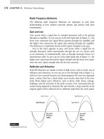
AppleTalk
AppleTalk is not just a protocol; it is a proprietary network architecture for Macintosh com-
puters. It uses a bus and typically either shielded or unshielded cable.
AppleTalk uses a Carrier Sense Multiple Access with Collision Avoidance (CSMA/CA)
technology to put data on the cable. Unlike Ethernet, which uses a CSMA/CD method (where
the CD stands for Collision Detection), this technology uses smart interface cards to detect
traffic before it tries to send data. A CSMA/CA card listens to the wire. If there is no traffic,
it sends a small amount of data. If no collisions occur, it follows that amount of data with the
data it wants to transmit. In either case, if a collision happens, it backs off for a random
amount of time and tries to transmit again.
4831x.book Page 444 Tuesday, September 12, 2006 11:59 AM