Modeling and Simulation for Material Selection and Mechanical Design Part 12 docx
Bạn đang xem bản rút gọn của tài liệu. Xem và tải ngay bản đầy đủ của tài liệu tại đây (464.94 KB, 18 trang )
and the workpiece under test) to the short-time tensile yield strength of the
softer contact body at the test temperature. The value of t is simply a mea-
sure of the resistance of the joint to shear. The friction condition at the sur-
face of a cutting tool will be similar to that for which the value of t was
measured.
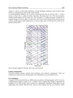
The results of the wear resistance tests are given in Fig. 6. As can be
seen, the wear resistance of HSS tools is 2.0–3.5 times lower than that of
DCPM tools. This reduction was associated with a significantly lower fric-
tion parameter of DCPM compared to HSS (Fig. 7), and a broadening of
the range of normal friction (Fig. 6). Within the normal friction range,
the rate of wear for DCPM is much lower than that for HSS (Fig. 6, curves
1–3). While the hardness and heat resistance values of the HSS T15 and
DCPM are similar, the wear resistance of the latter is significantly higher
(Table 3). In our opinion the lower wear intensity of the DCPM-tool mate-
rial is related to the presence of titanium carbides in the structure and their
subsequent transformation to oxygen-rich compounds during cutting.
When studied by secondary ion mass spectroscopy (SIMS), the analy-
sis of typical wear craters revealed the formation of oxygen-containing
phases. The data in Fig. 8 demonstrate that the transformation of titanium
carbide into an oxygen-containing phase starts in the initial stage of wear
(during the running-in process, Fig. 8a). With further operation, there is
increased surface oxide formation at the bottom of the wear crater. This
process is accompanied by stabilization of the wear processes (Fig. 6 and
8b,c) and an expansion of the normal friction range. Evidently, this is deter-
mined by the phenomenon of self-organization that is connected with the
emergence of secondary structures (titanium–oxygen compounds), which
play the role of stable solid lubricants [25].
Figure 6 The dependence of the flank wear value of cutting tools on the cutting
time: (1) HSS M2; (2) HSS T15; (3) DCPM. Turning test data acquired with 1040
steel. Parameters of cutting: speed (m=min): 55; depth (mm): 0.5; feed (mm=rev):
0.28.
Copyright 2004 by Marcel Dekker, Inc. All Rights Reserved.
Figure 9 Microphotograph of tool friction surface with films of secondary
structures: (a) general view of the surface using secondary electrons; (b) distribution
of oxygen close to the ‘‘built-up-crater’’ contact surface (SI, intensity of signals,
arbitrary units).
Copyright 2004 by Marcel Dekker, Inc. All Rights Reserved.
electron spectroscopy, are given in Fig. 9(b). In the left part of the
micrograph (a), a build-up of 1040 C steel can be seen. The right part of
the micrograph shows the distribution of dispersed hardening phases in
the HSS-based DCPM. Angular (dark) particles of titanium carbide (less
than 8 mm in cross-section) as well as disper sed tungsten and molybdenum
carbides (less than 0.2–1.5 mm in diameter) are uniformly distributed in
the HSS matrix. In the surface layers of the tool material, we can observe
a zone of intense plastic deformation less than 5 mm in depth. There, dis-
persed particles of a titanium-containing phase have been drawn out parallel
to the wear surface, forming a discontinuous film. The titanium carbides in
the wear zone have been transformed into oxides (Fig. 8 and [23]). Titanium
oxides are known to be much more plastic than titanium carbides, account-
ing for the plastic deformation of the particles in the surface layers of the
HSS-DCPM on cutting.
These results are confirmed by Auger-spectroscopy. Fig. 9(b) repre-
sents the distribution of the intensity of the characteristic Auger KLL lines
for O, C, and the LMM (418 eV) line of Ti along the I–I direction in
Fig. 9(a). The analysis volume includes the built-up layer (of 1040 steel),
the built-up layer=wear crater boundary, and the DCPM volumes beneath
the wear crater. At the interface, the titanium compounds show an increased
concentration of oxygen and a decreased carbon content. The observed
change in chemical composition is related to the instability of titanium car-
bide. Due to the high cutting temperatures (in excess of 4508C) and pro-
nounced affinity for oxygen, titanium adsorbs the latter from the
environment and forms thin films of oxygen-containing compounds, in
agreement with the SIMS data presented in Fig. 8. The total plastic defor-
mation of these particles at the wear surface is greater than 600%. The crys-
tal structure of these compounds is believed to differ from the titanium
oxides that would be obtained under equilibrium conditions (see below).
An understanding of the self-organizing phenomenon is critically
important for the development of advanced tool materials. A major interest
in these studies (from the point of view of materials science) is the nature of
the secondary structures forming under severe cutting conditions. According
to the principles of current tribology, one of the main methods to control
friction is the creation of stable secondary structures at the tool surface.
The more stable are the secondary structures, the greater will be the tool life.
The development of protective secondary structures can be manipulated by
alloying or by surface treatment technologies. The type of secondary struc-
tures formed during cutting depends strongly on the conditions of cutting
and the type of the material under analysis.
A detailed study of the physico-chemical parameters of the SSs formed
during cutting using a tool made of DCPM was done using AES, ELS, and
Copyright 2004 by Marcel Dekker, Inc. All Rights Reserved.
EELFS methods. To interpret the atomic structure of the tool wear surface,
data obtained in this work by the EELFAS method were compared to TiC
and TiO
2
standards. Fig. 10 presents the Fourier transform of data obtained
on analyzing the extended electron energy loss fine structure (EXELFS) for
titanium carbide (TiC) with a cubic (B1) structure. The positions of the main
peaks (Fig. 10a) are consistent with the interatomic distances for a (1 0 0)
plane in the cubic lattice of titanium carbide (see Fig. 10b).
Figure 10 (a) Fourier transform of EELFS close to the line of back-scattered
electrons for TiC specimen, Ep¼1500 eV; (b) cubic lattice of titanium carbide (¼Ti;
¼C).
Copyright 2004 by Marcel Dekker, Inc. All Rights Reserved.
Fig. 11(a) shows data for TiO
2
with the rutile (C4) structure. We can
identify the type of bonds by using partial functions F(R) obtained from the
analysis of the fine structure of spectra close to the characteristic Auger lines
of oxygen and titanium. By comparing these data with those given in
Fig. 9(a), we can see that TiO
2
has a more complex crystalline structure
than TiC. This explains the greater number of F(R)-function peaks.
The positions of the main peaks are again in good agreement with the
Figure 11 (a) Fourier transform of EELFS close to the line of back-scattered
electrons for TiO2 specimen with rutile structure, Ep¼1500 eV; (b) cubic lattice of
titanium oxide (¼Ti;
¼O).
Copyright 2004 by Marcel Dekker, Inc. All Rights Reserved.
interatomic distances for a (1 0 0) plane in the TiO
2
lattice. The complete
analysis of all the peak positions by the Fourier transform method shows
that the interatomic distances O–O and Ti–O in the secondary structures
are different from those discussed in the literature (see Fig. 11b). This
may be related to a deviation from stoichiometry, or the interatomic dis-
tances, measured from an analyzed volume that is only several angstroms
thick near the surface, are different from the equilibrium values.
The evolution of the atomic structure in the surface films on the wear
crater of the cutting tool is well illustrated by the data given in Fig. 12. The
oxygen-containing films in the wear crater are significantly enriched with
titanium and oxygen after only 5 min of cutting (see Fig. 12a–d). As this
takes place, a periodicity in the arrangement of atoms of various types is
observed both in the nearest coordination sphere and at greater interatomic
distances, up to approximately 7 A
˚
(see Fig. 12b).
As noted above, the interatomic distances in these oxygen-containing
films differ from those observed in equilibrium titanium oxides, including
rutile (compare with Fig. 11). The very thinnest films may be 2D (two-
dimensional) phases whose atomic structure is close to the supersaturated
a-solid solutions of oxygen in titanium. After 15 min of cutting, the degree
of long-range order is reduced, while the intensities of peaks from higher
order coordination spheres are less pronounced (see Fig. 12c). After
30 min of cutting (Fig. 12d), the translational symmetry at large interatomic
distances disappears, and peaks at R > 4A
˚
are lost.
The adaptability of the surface layer to external thermo-mechanical
effects is the physical basis of such evolution. The surface is gradually con-
verted to an amorphous state during the wear process (after cutting times of
about 15 min). When a steady-state condition is reached, i.e., after the devel-
opment of the SS is completed, the surface generates amorphous-like films
having an effective protective function. The lattice instability of the solid
solution of oxygen in titanium finally leads to complete amorphization of
the water surface. A similar effect was observed earlier from EELFS data
for TiN-coatings on worn cutting tools [26].
Typical EELS spectra of TiC, TiN, TiO
2
obtained with a 30.0 eV pri-
mary electron beam are shown in Fig. 13. The elastic peak has a 30 meV
FWHM (full width at half maximum). The high-resolution structures of
the spectra are represented at 1000 Â magnification after normalizing.
The experimental curves are approximated by Gaussian peaks in each spec-
trum in the range of 1–9 eV energy loss.
In the series of titanium compounds TiC–TiN–TiO, the number of 4s
electrons in the atomic sphere of the metal decreases from the carbide to the
oxide. These electrons are transferred to the 2p orbital of the non-metal
atom, and the band energy is lowered due to the increasing Ti–X attraction
Copyright 2004 by Marcel Dekker, Inc. All Rights Reserved.
this orbital is more completely filled in the case of oxygen than in either
nitrogen or carbon. For this reason, when the 3d Ti- and 2p X orbitals
are hybridized, the contribution of the ds-electrons of Ti is less pronounced
in the oxide and more expressed in the nitride and carbide. Consequently,
the oxide has considerably less strength and hardness than the carbide or
nitride [27].
The interaction of Ti–Ti atoms is realized at the expense of dp-elec-
trons. The metallic nature of this compound is related to the high density
of dp-electrons. As seen in Fig. 13, the intensity of t
1g
! t
2g
transitions in
the p-band is relatively insi gnificant in TiC, but it is much higher in TiO
2
.
This implies that the density of conduction electrons is low in TiO
2
but it
is higher for TiC and TiN. This is consistent with the electrical conductivity
data of these compounds, which is extremely low for the dielectric TiO
2
, but
16,400 (Ohm m)
À1
for TiC and TiN, respectively [27].
The replacement of carbon with oxygen in titanium compounds was
shown to change their properties significantly. Thus, the oxidation of TiC
at 823 K for 30 min influences the electronic structure of the material, the
electron spectrum acquiring some features specific to TiO
2
(see Figs. 14a
Figure 14 Representative ELS spectra: (a) after oxidation of TiC by heating up to
823 K for 30 min in air; (b) wear surface of DCPM cutting tool after 5 min of
operation; (c) wear surface of DCPM cutting tool after 30 min of operation. The
spectra were obtained using a 30.0 eV primary electron beam.
Copyright 2004 by Marcel Dekker, Inc. All Rights Reserved.
and 13c). After oxidation of TiC, the intensity of the lines at 6.7 and 1.6 eV is
substantially enhanced. On oxidation, the titanium carbide loses its metallic
properties and acquires those of a dielectric. In this case, we observe a
reduced concentration of conduction electrons and a localization of the elec-
tron density both in the metal and non-metal atoms. This is shown by the
increased intensity of the peak at 1.6 eV corresponding to p-states in the
3dd-band of titanium (see Fig. 13a).
It was noted earlier that an intense oxidation of TiC could be observed
during the operation of a DCPM tool [20,22]. In this case, the nature of the
phase transformation differs significantly from that found on heating a TiC
standard up to 823 K for 30 min. Figure 14(b) and (c) presents electron
energy loss spectra from the wear crater after 5 and 30 min of DCPM-tool
operation. As the weartimeincreases, the spectra display a somewhatincreased
intensity of peaks at 6.8 and 3.1 eV. Peaks corresponding to plasmon losses
(p1 and p2) appear, while the peak at 1.6 eV is significantly attenuated.
The thin SS films in the wear crater of the cutter are associated with
the formation of supersaturated solid solution of oxygen in titanium due
to the oxidation of titanium carbide. In this case, we observe an increase
in the electron density in the 2p orbital of the non-metal (peak 6.8 eV) as
well as an enhanced filling of the ds-electron band of titanium atoms (peak
3.1 eV). These effects are similar to those encountered in the model oxida-
tion of TiC (Fig. 14). There are, however, substantial differences. As the cut-
ting time increases, the effects brought about by the crystalline structure
of phases become significantly weakened in the electron spectrum. The
splitting of the 3d orbital into p and s-states degenerates, the intensity of
t
1g
!t
2g
transitions is reduced as well as the density of p-electrons which
are related to the long-range Ti–Ti bonds in the lattice (along the diagonals
in the (1 0 0) planes). These distinctive features of the electron structure are
related to amorphization and to the increasing role of short-range inter-
atomic bonds. Of considerable interest is the appearance of plasmon loss
peaks p1 and p2 in the spectra of Figs. 14(b,c) due to the growing concen-
tration of conduction electrons. The delocalization of p-electrons close to
the titanium atoms enhances the metallic nature of bonds in the amorphous
films developed on the friction surface. These specific traits of electronic and
atomic structural change might help to explain the unique mechanical prop-
erties in the secondary structures of the first type. The high wear resistance
and good frictional properties of DCPM tools are associated with complex
structural and phase transformations on the surface, among them TiC oxi-
dation and the development of thin protective amorphous films. The SSs are
saturated or supersaturated (amorphous) solid solutions of oxygen in
titanium, whose electron structure is characterized by a high density of con-
duction electrons giving metallic characteristics.
Copyright 2004 by Marcel Dekker, Inc. All Rights Reserved.
These results show that the SSs formed during cutting not only
increase the DCPM-tool life but also change friction characteristics as well.
The amorphous-like secondary structures of the first type behave like a solid
lubricant with enhanced tribological properties [4].
Additional alloying of the DCPM might be beneficial. For example,
the partial substitution of titanium carbide by aluminum oxide, which is
stable under cutting leads to a decrease in the friction coefficient (Fig. 15)
Figure 15 Impact of the test temperature on the wear and friction characteristics
as determined from wear contact tests for the DCPM with 15% TiC þ5% Al
2
O
3
;
20% TiCþ2% BN and 20% TiCN additions.
Copyright 2004 by Marcel Dekker, Inc. All Rights Reserved.
and in an increase in the wear resistance of the tool (Fig. 16). The decrease
of the friction coefficient when Al
2
O
3
is added is important not only as it
increases the wear resistance but also because it lowers the cutting tempera-
ture at the tool surface [28,29]. Alloying often cannot be implemented by the
traditional metallurgical methods since this may induce an undesirable
change in the prope rties of the cutting material. We took a different
approach by making small additions of low-density compounds, which
are relatively unstable at the operational temperatures. This allowed us to
use this compound in relatively small quantities (up to 2 w%) with minimal
possible impact on the bulk properties. The solid lubricant (hexagonal BN)
was chosen as the additional alloying compound [28]. The high probability
of oxygen-containing secondary phases formed from BN during cutting was
also taken into account. The possibility that TiC and BN might oxidize and
generate thin surface oxide films for exploitation in cutting tools can be
assessed by a thermodynamic approach [27].
Secondary ion mass spectroscopy investigations have shown that on
cutting DCPM with a boron nitride addition, oxygen-containing com-
pounds develop at the wear-crater surface, associated with a set of parallel
disassociation reactions of BC, BN, TiC leading to the formation of BO,
TiO and TiB,N. Figure 17a–c presents spectra of the positive and negative
Figure 16 Wear curves of friction contact materials: (1) DCPM with 20% TiC;
(2) DCPM with 20% TiC and 2% BN; (3) DCPM with 15% TiC and 5% Al
2
O
3
;
(4) DCPM with 20% TiCN. Turning test data acquired with 1040 steel. Parameters
of cutting: speed (m=min): 90; depth (mm): 0.5; feed (mm=rev): 028.
Copyright 2004 by Marcel Dekker, Inc. All Rights Reserved.
spectroscopy was done to demonstrate this phenomenon for the phases that
form on the wear crater surfaces of M2 high-speed steel, DCPM and BN-
doped DCPM tools. Figure 19a–c show Fourier transforms obtained from
data collected from the surface of wear craters in HSS and DCPM alloyed
with either TiC or TiC with BN. The F(R) functions feature pronounced
peaks in the range 1–2, 4–5 and 7–8 A
˚
for all cases. Using partial F(R) func-
tions obtained by analysis of the fine structures close to the Auger lines of C,
B, and Ti, it was possible to interpret the nearest-neighbor interatomic
bonds. It was found that Fe–O bonds are typical of the HSS sample, while
B–O and Ti–B bonds are observed at the wear crater of the BN-doped
DCPM sample.
The results of these investigations have shown that the composition of
the tool material not only determines the composition of the phases devel-
oped at the friction surface in the cutting zone, but it also exerts an influence
on the perfection of the crystalline structure of the new phases. The thinnest
films of iron oxide formed on the HSS-tool friction surface are crystalline,
Figure 18 Change in absolute and relative values of the peak intensity of the
secondary ion mass spectra for the BN-doped DCPM tool at different depths
beneath the surface of the wear crater developed after 4 min cutting.
Copyright 2004 by Marcel Dekker, Inc. All Rights Reserved.
the TiO family. The amorphization of secondary structures probably
depends on the DCPM composition and on increases in the level of BN-
alloying. One can see that the wear resistance of this material is increased
by 80% compared to the carbide steel having a base composition with
20% TiC (Fig. 16). This suggests that alloying enhances the stability of
the secondary structures developed during friction. This is promoted by
the presence of BO-type compounds that act as liquid lubricants [at elevated
cutting temperatures [28]] and promote the stability and the self-organiza-
tion of the complex compounds. This is of paramount importance for tool
wear resistance. The thickness of the stable secondary structures layer does
not exceed 0.1–0.15 mm (Fig. 18).
Finally, it is possible that such alloying of DCPM provides both a
reduction in the friction coefficient and a broadening of the normal wear
stage. In our opinion, the same goal can also be achieved in HSS-based
DCPM by the substitution of TiC with TiCN. Figures 15 and 16 demon-
strate that this substitution is extremely effective, decreasing the friction
coefficient to abnormally low values (in the range of 0.03–0.05) at a service
temperature of 500–550 8C, and signi ficantly increasing the tool life (Fig. 16).
In this case, the self-organization mechanism differs somewhat from the pro-
cess found for materials alloyed with BN. With TiCN the diffusional transfer
of nitrogen into the chip arises from dissociation of TiCN during cutting [26].
The increased nitrogen concentration on the contact surface of the chip is a
direct consequence of the mass transfer of nitrogen, formed by dissociation
of nitrides and carbo-nitrides. Such mass transfer takes place under the
extreme temperature and stress conditions encountered in the friction zone.
Therefore, the selection of titanium carbo-nitride for cermets and tita-
nium nitride as the hard phase in Sandvik Coronites seems to be completely
reasonable from the standpoint of tribological compatibility. The behavior
of titanium nitride should be comparable to a carbo-nitride [24,30] and this
has been confirmed experimentally by the analysis of the self-organizing
phenomenon of PVD TiN coatings (see below).
Another important factor is the thermal stability of DCPM com-
pared to cemented carbides. The importance of the thermal stability of this
type of material is evident at elevated cutting speeds. One way to improve
this property is to increase the volume fracture of the hard phase in the
DCPM; e.g., Sandvik Coronite has 50% of the hard phase (TiN) [30]
and its wear resistance is higher than either HSS or cemented carbides
(Fig. 20). So the benefits of an adaptive material are obvious from the
standpoint of both wear resistance and tribological compatibility. However,
the application of these materials is currently limited, although the pro-
blems encountered might be partially solved by improved surface-
engineering techniques. For example, state-of-the-art coating technologies
Copyright 2004 by Marcel Dekker, Inc. All Rights Reserved.
with high strength and toughness of the core. The intermediate layer has
graded properties that lie between those of the core and the surface.
Promising developments in this field have been reported by the Laboratory
of Materials Processing and Powder Metallurgy of the Helsinki University
of Technology. They developed a novel functionally graded material hav-
ing a surface ceramic layer, a graded WC-cermet composition with high
crack resistance and a cemented carbide core with excellent toughness. A
high crack resistance parameter value (K
1C
¼25 MPa m
1=2
) at a hardness
of 1500 HV (typical for tool steels with half the hardness) was found
(http:==www.hut.fi=Units=LMP=).
There are two methods used for FGM processing. The first one,
noted above, is a surface-engineering method. This method has unique
possibilities and versatility. But other methods, principally those based
on powder metallurgy, are also widely used. Combinations of these
two methods have recently been put into practice. Thus, tools manufac-
tured by ordinary sintering processes, having high-toughness cemented
carbide substrates with high wear resistant ceramic coatings and func-
tionally graded interlayers show excellent wear resistance [31]. Function-
ally graded materials can have superior wear resistance, resistance to
fracture, and good thermal shock resistance in the comparison to con-
ventional cermets, with a beneficial compressive residual stress distribu-
tion [32]. Ceramics have also been recently developed with functionally
graded structures. In order to combine high hardness and high tough-
ness, graded ceramics of Al
2
O
3
þTiC (surface)=Al
2
O
3
þTi (inner core)
and sialon (inner core) have been successfully developed [33]. Function-
ally graded ceramic tools can exhibit better cutting performance than
regular ceramic tools [34]. Functionally graded materials have also been
successfully used for milling applications [35]. Functionally graded pow-
der materials are normally used for high-speed cutting, but they can also
be successfully employed in the domain of HSS tools application
particularly with functionally graded cement carbide and hard PVD
coatings [36]
III. TRENDS IN THE DEVELOPMENT OF
SURFACE-ENGINEERED TOOL MATERIALS
Surface engineering has recently become one of the most effective ways of
improving the wear resistance of tool materials. The principal beneficial
effects associated with surface engineering for this application are shown
in Table 4.
Copyright 2004 by Marcel Dekker, Inc. All Rights Reserved.
to vary the parameters of deposition, using a regular PVD unit, to optimize
the coating properties and coating design.
A study designed to optimize the deposition parameters for TiN coat-
ings [38] determined that the nitrogen pressure is the most critical process
parameter responsible for changes in the coating structure and properties
of the films. For the deposition conditions described in Ref. [38], an increase
in the nitrogen pressure up to 0.4–0.6 Pa leads to stoichiometric TiN
(53 at.% N
2
). Further increases in the nitrogen pressure lead to a decrease
in the nitrogen concentration of the film (to 43 at.% N
2
, Fig. 21a). This is
probably caused by a decreased intensity of the plasma-chemical reaction
as a result of a reduction in the flux and energy of the impinging ions.
The phase composition changes from a-Ti þTi
2
N at very low nitrogen pres-
sures to TiN at higher nitrogen pressures (0.4–0.6 Pa).
The structural parameters of the film also depend on the nitrogen con-
centration in the coating. The lattice parameter and subgrain size (or equiva-
lently the dislocation density) are related to the nitrogen concentration in
the coating (Fig. 21b–d) and have maximum values at a composition corre-
sponding to stoichiometric TiN. An increase in the nitrogen pressure leads
to a pronounced axial texture (Fig. 21e), with (1 1 1) planes in the TiN be ing
parallel to the substrate surface. The (1 1 1) axial texture increases to 95% as
the gas pressure is raised to 0.6 Pa and remains practically unchanged with
subsequent pressure increases. The residual compressive stress in the coating
shows similar trends (Fig. 21f), with the stress increasing from 200 to
1300 MPa as the gas pressure is raised to 0.6 Pa. The rate of increase in
the compressive stress slows with a further increase in the nitrogen pressure
up to 2.6 Pa, reaching a maximum value of 1600 MPa. It is important to rea-
lize that the trends shown by these structural-dependent parameters depend
primarily on the deposition conditions. An increase in the nitrogen pressure
over 1.3 Pa decreases the ion energy, and the effective temperature at the
TiN crystallization front decreases. At a nitrogen pressure in excess of
1.3 Pa, the coatings form under conditions similar to those encountered in
the balanced magnetron sputtering process (for the PVD method). These
conditions can be indirectly characterized by the deposition rate, which
should not exceed 5–6 mmhr
À1
. A decrease in the deposition rate enhances
both the axial texture and the magnitude of the residual stresses. The most
probable cause of the high compressive residual stress found in thin con-
densed films deposited at nitrogen pressures greater than 1.3 Pa is a high
density of point defects [39]. An increase in the nitrogen pressure also
decreases the crystallite dimensions (Fig. 21f).
The microhardness of the coatings depends on their phase composi-
tion. The maximum microhardness (H
0.5
¼45 GPa) is achieved when the
two-phase a-TiþTiN composition changes into the three-phase composition
Copyright 2004 by Marcel Dekker, Inc. All Rights Reserved.
from stoichiometry causes a decrease in the Palmquist toughness, particu-
larly when a second phase is formed in the coating (e.g., Ti
2
N). This result
seems unexpected at first, but we should remember that the coating should
be regarded as a quasi-brittle material, whose toughness is determined pri-
marily by its crack propagation resistance. The optimum nitrogen con-
centration corresponds to the largest lattice parameter [40], although the
Figure 22 The dependence of the properties of TiN PVD coatings on the nitrogen
pressure.
Copyright 2004 by Marcel Dekker, Inc. All Rights Reserved.
microhardness of the coating with this structure is not relatively high. In
addition to the intrinsic mechanical properties of the coating, the level of
the residual compressive stress is important for crack initiation and propa-
gation. The value of the residual stress is about À800 MPa in stoichiometric
TiN coatings (Fig. 21f). The fracture resistance also appears to depend on
the columnar grain size, which again can be controlled if balanced deposi-
tion conditions can be achieved. The adhesion of the coating to the substrate
and the shear load resistance (i.e. the cohesion of the coating) both decrease
as the nitrogen pressure is increased. The nitrogen atoms (ions) in the
plasma scatter the Ti ions, so that the net effect of Ti ion bombardment
of the coating is reduced as the nitrogen gas pressure rises. As noted earlier,
both the axial texture and the residual stress gradient at the coating–
substrate interface increase as the pressure rises, and consequently the adhe-
sion of the coating falls (Fig. 22b). The coating wear resistance during dry
sliding friction under high loads (Fig. 22c) reaches its maximum value in
the three-phase field area a-TiþTiNþTi
2
N.
Cutters made of a high-speed steel with TiN coating are used under
adhesive wear conditions [3]. The tool life of TiN coated parts then depends
on the friction coefficient under cutting conditions that are close to galling
or seizure during wear testing (Fig. 22, e).
The overall conclusion of this study is that the optimum combination
of properties of the coating for adhesion wear is obtained at low deposition
rates (for the PVD method) of 5 mmhr
À1
and a stoichiometric composition
of TiN. This can be achieved by optimizing the deposition parameters. In
this case, the hardness and toughness increase, while the shear resistance
decreases. A coating with the optimum structure will crack by shear failure
at or near to the surface of the coating rather than forming deep cracks lead-
ing to a catastrophic failure of the whole tool. However, at the same time,
the shear stress resistance of the coating should be strong enough to allow
for easy flow of the chip (the value of cohesion should be about 0.2). Since
a monolithic TiN coating usually has a low adhesion to the substrate, adhe-
sive sublayers are necessary to achieve high efficiency from this type of
coating.
A number of principles guiding the selection of the processing of TiN
multi-layer coatings for adhesive wear conditions can be proposed from this
study. The coating should have at least three sublayers:
(1) An adhesion sublayer, deposited with substoichiometric nitrogen.
These deposition conditions provide the maximum kinetic energy of
the ions and a low nitrogen concentration in the layer (up to 35%). At
the same time the (1 1 1) axial texture should not exceed 50%, while the
residual stress at the coating–substrate interface should be low (not
Copyright 2004 by Marcel Dekker, Inc. All Rights Reserved.
more than 200 MPa). When this combination is achieved, the adhesion
of the sublayer is high.
(2) A transition layer deposited with a gradual increase in the nitrogen
pressure to provide:
(a) development of an axial (1 1 1) texture (from 48% up to 100%)
from the substrate to the top layer;
(b) a residual compressive str ess increase from 200 MPa in the
adhesion layer up to 1700 MPa; and
(c) a gradual transition from a three-phase structure a-TiþTiNþTi
2
N
to single phase TiN.
(3) A working (contact) layer, deposited under high nitrogen pressures and
balanced conditions (the deposition rate for the CAPDP method is 5–
6.5 mmhr
À1
). In addition the deposition conditions at this stage should
be chosen to yield stoichiometric TiN, having a nearly perfect axial
texture, a high residual compressive stress (more than 2000 MPa), and a
fine columnar grain size containing minimal ‘‘droplet’’ phases.
A multi-layer coating is required to meet these diverse requirements.
This coating offers many advantages (in comparison to monolithic coatings)
in satisfying the broad range of mechanical properties needed in these appli-
cations. It has high adhesion to the substrate but low adhesion to the
workpiece (i.e. a minimal friction coefficient), a high microhardness
(H
0.5
¼35 GPa) and a high toughness (mor e than 50 J m
À2
, see Table 5). This
favorable blend of structural and mechanical properties has many advan-
tages for wear resistance during cutting operations (Table 5).
Table 5 Comparative Characteristics of TiN Coatings Deposited by the PVD
Method on the Coating Deposition Process [38]
Parameters
PVD method
Coating
design
Microhardness
(GPa)
Palmquist
toughness
(N m
À2
)
Coefficient
of adhesion
to the
substrate
Wear resistance
on cutting
Regular arc
deposition
Monolithic
coating
25.0 26.0 0.5 1.0
Multi-layer
coating
30–35 50–60 0.8 1.5–2.0
Filtered arc
deposition
Multi-layer
coating
35–37 150–200 0.8 2.0–2.5
Copyright 2004 by Marcel Dekker, Inc. All Rights Reserved.
The same multi-layer coating could be used for filtered PVD coat-
ings with the additional advantages offered by this technology [41]. These
systems not only eliminate the ‘‘droplet’’ phase from the coating, but
they can also be used to control the deposition conditions so that an
excellent microstructure and properties are obtained in the film. An extre-
mely fine-grained structure (the grain size is 10 nm in comparison to a
grain size of several microns in regular coatings) can be achieved [42],
with excellent mechanical properties. The nano-grained structure of the
film is due to:
(1) the higher ionization rates achievable in filtered arc-evaporated
plasmas, which are thought to enhance the nucleation rate and depress
the growth rate of coarse crystals; and
(2) a lower overall deposition rate for the filtered arc PVD process that
results in a drop in the temperature at the growth front of the film.
Although lower deposition rates are found with this process and can
lead to a loss of productivity, these disadvantages can be offset by improve-
ments in the quality of the film. The hardness and Palmquist toughness of a
TiN coating deposited by this method can be increased up to 35–37 GPa
(instead of 25 GPa) and 150–200 J m
À2
(instead of 26 J m
À2
), respectively.
The adhesion of this coating is also very high (k
adh
¼0.8, see Table 5). In
addition, the wear resistance of filtered coatings is usually much better than
regular coatings (Table 5). The principles outlined above for a multi-layered
TiN coating can also be successfully applied to filtered coatings.
1. Frictional Wear Behavior and Self-Organization of
TiN PVD Coatings
Hard TiN coatings act as surface lubricants by inhibiting the adhesion of the
tool surface to the workpiece [1]. The friction parameter of this coating is
also low at the operating temperature (Fig. 23). The wear behavior changes
when TiN coatings are applied to cutting tools (Fig. 24a) [43]: the initial rate
of wear (during the running-in stage) is significantly lower and the range of
normal wear is expanded. As a result, both reduced friction and wear con-
trol can be achieved (see Fig. 2). To explain the enhanced wear characteris-
tics imparted by TiN PVD coatings, a study of the self-organization
behavior of the tool was performed [26]. Protective secondary structures
(SS-I) of the Ti–O type form at the surface of hard PVD TiN coatings dur-
ing cutting. The transition from the running-in stage to the normal wear
stage is marked by the development of a supersaturated solid solution of
oxygen in titanium (Fig. 25a–c). At the same time, as the friction drops,
Copyright 2004 by Marcel Dekker, Inc. All Rights Reserved.