Plastic Product Material and Process Selection Handbook Part 10 pptx
Bạn đang xem bản rút gọn của tài liệu. Xem và tải ngay bản đầy đủ của tài liệu tại đây (2.29 MB, 35 trang )
6. Blow molding 299
blowing operation that provides radial stretch and orientation (Figure
6.11). Blowing pressures range up to about 40 bar. The blow mold
temperature is relatively high at 35 to 65C in order to minimize strain
in the bottle. For a given bottle size, the degree of orientation is
determined principally by the parison length and diameter. Stretch
ratios are relatively high. In the wall thickness of the bottle body, the
amount may be as high as 15:1. Axial stretch is about 4:1; diametrical
stretch ranges about 3.5:1
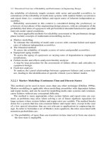
Figure Gotl Example of stretched injection blow molding using a rod (left) and example of
stretched injection blow molding by gripping and stretching the preform
With the two-stage process, processing paramctcrs for both preform
manufacturing and bottle blowing can be optimized. A processor does
not have to make compromises for preform design and weight,
production rates, and bottle quality as done on single-stage equipment.
One can either make or buy preforms. And if one chooses to make
them, one can do so in one or more locations suitable to the market.
Both high-output machines and low out-put machines are available.
The two-stage process, which permits injection molding of the preform
and then shipping to BM locations, has allowed companies to become
preform producers and to sell to BM producers. Thus companies that
wish to enter the market with oriented containers can minimize their
capital requirements.
Extrusion stretch blow molding (ESBM) is a one-stage or two-stage
process using two mold/mandrel sets where one is for preblow and the
other for final blow. An extruded parison is first pinched off and blown
300 Plastic Product Material and Process Selection Handbook
conventionally in a relatively small preblow mold to produce a closed-
end preform. The preform is then transferred to the final blow mold
where usually an extending stretch rod within the blowing mandrel
bears on the closed preform end to stretch it axially. The stretched
preform is then blown to impart circumferential stretch. Standard BM
machines can be converted for extrusion stretch BM. The process is
most often used for PVC bottles.
Oriented PVC containers most commonly are made on single-stage,
extrusion-type machines. The parison is extruded on either single- or
double-head units. Temperature conditioning, stretching, and thread
forming are done in a variety of ways depending on the design of the
machine. Many of the processes in use are proprietary.
Dip Blow Molding
The dip BM process bears some resemblance to IBM in that it is a
single-stage process performed with a preform on a core/blow pin.The
difference is in the way the preform is made. The process uses an
accumulator cylinder that is fed by an extruder. The cylinder has an
injection ram at one end while the other is a free fit over the blow pin.
The blow pin is dipped into the melt so that a neck mold on the pin
seals the end of the accumulator cylinder. The injection ram is advanced
to fill the neck mold; then the blow pin is withdrawn at a controlled
rate so that it is coated with a melt layer extruded through the annular
gap between the pin and the accumulator cylinder. The thiclcness of the
coating can be varied or profiled to an extent by varying the speed of
the blow pin and the pressure on the injection ram. After trimming, the
preform is BM in the same manner used for IBM.
The process results in a seam and flash free container with a high quality
molded neck. The preform is produced at a lower pressure than that
used for injection molding, so the machine can be lighter and of lower
cost constructed. The preform is formed under relatively low stress.
Process is best suited to the production of smaller containers.
Multiblow Blow Molding
The process is used for high volume BM of very small containers such
as pharmaceutical vials and whiskey bottles. A multi-cavity mold is used
with an extruded parison whose circumference approaches twice the
total width of the closely spaced cavities. Before the mold closes, the
parison is stretched and semi-flattened laterally so that it extends across
the full width of the cavities. The process is usually combined with
blow/fill/seal techniques.
6-Blow molding 301
Sequential Extrusion
Sequential EBM is a special multi-material technique used for the pro-
duction of special designed products. The different plastics are chosen
typically to contribute complementary mechanical properties and are
present in distinct sequential zones in the finished part. Normally two
materials are used but three or more are also used. Separate external
ram accumulators for each material serve the die head. These are
operated sequentially, typically in A-B-A sequence, to produce a parison
with three distinct material zones in axial succession. The parison is
subsequently BM by normal techniques.
An example for sequentially BM polypropylcnc is an automotive air
duct in which a central flexible zone (Figure 6.12) joins rigid end
sections. The flexible zone allows for installation mismatches, accom-
modates thermal expansion, and damps vibration noise. The rigid
portions allow for direct connection to other mechanical elements in
the assembly.
Figure 6~ 12
Examples of different shaped sequential extrusion blow molding products
302 Plastic Product Material and Process Selection Handbook
Blow/Fill/Seal
The blow/fill/seal process is a complete packaging technique that
integrates the extrusion or IBM and container filling steps. This can
provide for aseptic filling of the hot as-blown container and is used for
pharmaceutical, food, and cosmetic products. The process employs a
two-part mold in which the container body mold cavity blocks are
separate from the neck-forming members.
The body mold closes on the parison that is blown normally by a neck
calibrating blow pin. Immediately, with the mold still closed, the liquid
contents are injected through the pin. The pin is then withdrawn and the
neck is formed and sealed under vacuum by the neck-forming members.
Both mold parts then open to eject a filled and sealed container. Small
containers may be formed entirely by vacuum rather than blowing.
Blow Molding 3-D
Because EBM is performed on a cylindrical parison, the conventional
process is not well suited to the production of products with complex
forms that deviate substantially from the parison axis. Such forms can
be produced by conventional BM equipment, but only by using a
parison that in its form blankets the complex mold cavity. This 3-D
process in the past usually developed an excessive amount of pinch-off
scrap. During the past few decades developments in parison handling
robot equipment and in blow mold design make it possible to
manipulate a relatively small parison into the complex mold cavity. The
result is a BM largely free of flash and scrap and offering considerable
process savings. There arc many such techniques, some of them
proprietary property, and they are collectively lcnown as 3-D blow
molding. Examples are shown in Figures 6.13 and 6.14.
Blow Molding with Rotation
The injection molding with rotation (MWR) is an example of
processing at lower temperatures, pressure, etc. It is also called injection
spin molding or injection stretched molding. This BM process com-
bines injection molding and IBM, as performed in IBM reviewed,
except it has the additional step of with melt orientation (Dow patent).
The equipment used is what is commercially available for IM except the
mold is modified so that either the core pin or outside cavity rotates.
The rotated melt on its preform pin is transferred to a blow mold. The
end product can come directly from the IMM mold or bc a result of
two-stage fabrication: malting a parison and BM the parison. 164
This technology is most effective when employed with articles having a
polar axis of symmetry; having reasonably uniform wall thickness; and
6. Blow molding 303
Figure 6o
t :3
Example of a suction extrusion blow molding process fabricating 3-D products
(courtesy of SIG Plastics International)
whose dimensional specifications and part-to-part trueness are
important to market acceptance. The MWR process requires no
sacrifice of either cycle time or surface finish. Both laboratory and early
(past) commercial runs identify good potentials for reducing cycle time;
for either reducing the amount of plastic required or improving
properties with the same amount of plastic, or both; and for sub-
stituting less expensive plastics while achieving adequate properties in
the fabricated product.
During fabrication using the MWR process, two forces act on the
plastic: injection (longitudinal) and rotation (hoop). The targeted
balanced orientation is a result of those forces. As the product wall
cools, additional high-magnitude, cross-laminated orientation is developed
frozen in and throughout the wall thiclmess. Orientation on molecular
304 Plastic Product Material and Process Selection Handbook
Figure 6,14
Examples of 3-D extrusion blow molded products in their mold cavities (courtesy of
SIG Plastics International)
planes occurs as each layer cools after injection. This orientation can
change direction and magnitude as a function of wall thiclcness. The
result is analogous to plywood or reinforced plastics (Chapter 15) and
the strength improvements are as dramatic. In the MWR process, there
is an infinite number of microscopic layers each of which has its own
controlled direction of orientation. By appropriate processing conditions,
both the magnitude and direction of the orientation and strength
properties can be varied and controlled throughout the wall thickness.
MOLD
Blow mold usually consists of two halves, each containing cavities
which, when the mold is closed, define the exterior shape of the BM
(Chapter 17). Multiple cavity molds are used. Because the process
produces a hollow article, there are no cores to define the inner shape.
Mold details and actions will vary considerably according to the
geometry of the product and the BM process in use. Even though the
following review concentrates on EBM, the information can also be
applied to IBM. The two halves that meet on a plane are known as the
parting line. The plane is chosen so that neither cavity half presents an
6-Blow molding 305
undercut in the direction of mold opening. For most bottle designs,
this requirement presents little or no difficulty.
For products of asymmetrical cross-section, the parting line is placed in
the direction of the greater dimension (Figure 6.1 5). Guide pillars/pins
and bushings to ensure that there is no mismatch between the cavities
align the two mold halves. With EBM the parison passes across the
mold in the axis of the cavity and is pinched and compressed between
the faces of the closing mold at the neck and base regions of the cavity.
These are known as the pinch-off zones. Separate inserted mold blocks
typically form the base and neck regions of the mold. The mold
includes channels for the circulation of cooling water.
F{gure
6,! 5
Example of a 3-part mold to fabricate a complex threaded lid
With injection BM the preform only has a pinch-off at the neck. In
EBM the pinch-off zone performs two functions. It must weld the
parison to make a closed vessel that will contain blowing air, and it must
leave pinched-off waste material in a condition to be removed easily
from the blown product. 164
Flash caused by the pinch-off is an unavoidable evil in EBM. Ability to
control the adverse effects of the flash is critical to success of the
process. 228 Pinch-off generates excess material in the form of flash that
is usually twice the thickness of the parts wall. This thicker plastic cools
slower than the blown product. It is subject to fold-over and can adhere
to the blown product. Flash imposes costly limits on BM efficiency. It
has potential for significantly extending the molding cycle, primarily by
increasing the time needed to cool the thick flash. This cycle increase
could approach twice what would normally be required. Removal calls
for a post-molding trim step that requires secondary equipment and
poses a risk of damaging good parts.
To reduce the time cycle a fabricator has some damaging options such
as ejecting the part before the flash is sufficiently cooled. Because it is
306 Plastic Product Material and Process Selection Handbook
still soft and pliable when ejected, it can create other problems such as a
fold over on itself and adhering to adjoining surfaces of the part after
ejection of the molding. Flash is also considerably more difficult to
handle and trim while hot. In either case, the resultant penalty may be a
significant increase in the part reject rate. By locating cooling lines as
close as possible to the flash heat transfer to the cooling water will
reduce cycle time. So it is critical to appreciate maximizing the heat
transfer as much as possible to the flash area. By keeping the water
turbulent takes advantage of operating the water in the proper
Reynold's number (Chapter 17).
When a parison is blown, a large volume of air must bc displaced from
the mold cavity in a short time. Because blowing is carried out at
relatively low pressure, it is essential to provide venting to allow this air
to escape without resistance. Unless a gloss finish is required on the
molding, it is common practice to sandblast the cavity to a fine matt
finish. This helps air to escape as the expanding parison touches the
cavity face but it is not sufficient in itself. Vent slots may bc cut at
appropriate points into the mold parting face to a depth of 0.05 to 0.15
mm. The appropriate point is where there is a possibility for air to
collect as the hot plastic expands in the cavity.
Venting can also bc provided within the mold cavity by means of inserts
equiped with vent slots, porous sintercd plugs, or by holes with a
diameter not greater than 0.2 ram. Such holes are machined only to a
shallow depth and arc relieved by a much larger bore machined from
the back of the mold.
Efficient mold cooling is essential for economical BM. As in injection
molding typically, up to 80% of a BM cycle is devoted to cooling.
Molds arc constructed as far as possible from high thermal conductivity
aluminum alloys, and water cooling channels arc placed as close as
possible to the surface of cavities and pinch-off zones. Because BM is a
relatively low pressure process, the channels can be quite close to the
surface and quite closely spaced before mold strength is compromised.
The actual dimensions will depend on the heat transfer rate and cooling
temperature requirements for the material of construction and plastic
being processed. As a guide, channels may approach within 10 mm of
the cavity and center spacing should not bc less than twice the channel
diameter. If the mold body is cast, the cooling channels can be
fabricated in copper pipe to closely follow the cavity contours before
being cast in place. If the mold is machined, drilling and milling will
produce channels, and it is not usually possible to follow the cavity
contours so closely (Chapter 17).
6. Blow molding 307
An alternative in cast molds is a large flood chamber (Figure 6.16).
However, efficient water cooling requires turbulent flow and this may
not be attained in a flood chamber or in large coolant channels
(Chapter 17). Many small channels are better than a few large ones.
The cooling circuits will normally be zoned so that different areas of
the mold can be independently controlled. The coolant flow rate
should be sufficient to ensure turbulent flow and to keep the
temperature differential between inlet and outlet to about 3C.
Figure 6~ 6 Examples of water flood cooling blow molding molds
THERMOFORMING
Introduction
Thermoforming is a process for converting thermoplastics into shell
forms, using plastic sheet or film as a preform. Processes permit
forming many small to large durable varied shapes. The various forming
techniques permit manufacture of products individually or on mass
production-continuous belt type production that are used in many
different markets. Products include machinery and tool housings,
industrial pallets, boat hulls, computer housings, transportation [auto,
bus, aircraft, etc.] components, refrigerator door liners, etc. Typical
products are high production items such as plates, cups, lids, trays,
containers, etc. Many different methods of thermoforming are used.
Figure 7.1 provides an introduction to the thermoforming methods.
With the exception of a few such as matched mold, hybrid billet
[combines thermoforming and blow molding, 24s and twin sheet
thermoforming, the forming process uses an open mold that defines only
one surface of the thermoformed part. The second surface is only in-
directly defined by the mold. This second surface will lack precision
definition of features to an extent dependent partly on the sheet thickness
and thickness tolerance as well as the uniformity in heat subjected to the
sheet prior to forming. ~, 28, 194, 229, 230, 231,232-237, 476 There is no direct
control over wall thickness of the formed part; this MI1 vary from feature
to feature according to the degree of stretch and thinning experienced at
that point. Normally, it will be a target in thermoforming to obtain as even
a wall thiclmess as possible in the finished part. Because the basic process
uses a sheet preform and a single-surface mold, it is not possible to create
independent features on the second surface. These processing consider-
ations confine most thermoformed parts to relatively simple shapes
however there are different complex 3-D parts formed.
7 9 Thermoforming 309
Figure 7ol
Examples of thermoforming methods
Identification of thermoforming is related to the thicl~ess of the plastic
processed. There are thin-gauge and thick-gauge or heavy-gauge
thermoforming processes. Thin-gauge identifies sheet thickness that is
less than 0.06 in. (0.15 cm). Film forming is a form of thin-gauge
forming where the plastic thickness is less than about 0.01 in. (0.025 cm).
310 Plastic Product Material and Process Selection Handbook
Heavy-gauge means that the sheet thickness is greater than about 0.1
in. (0.25 cm). There is also plate forming or heavy-gauge forming
where the sheet thicl~css is greater than about 0.4 in. (1 cm).
Although polystyrene and polyolefin foam sheet thicl~csscs can exceed
0.01 in. (0.25 cm), these foams are usually treated as thin-gauge sheet
stock. This classification is also used to further classify forming by
machinery type, product type, and processing problems.
To form thermoplastic sheets or films they must be heated to the
drawing temperature just prior to and during the drawing cycle that
uses a forming force. The plastic can be heated in an oven, heated
tunnel, on a mold plate, or preheated on a hot plate. Plastic is heated
only a few degrees above its glass transition temperature (Tg) or melt
temperature (Tin) (Chapter 1). Combinations of preheating with mold
heating have advantages particularly in production runs. Target in
heating plastic material to bc thcrmoformed is to heat rapidly with a
minimum temperature gradient from its edge to center and throughout
the sheet thickness. The material when formed in the mold or dic is
held in position by some mechanical device such as clamps or pressurized
hold-down plates. During forming the heated flexible/rubbery sheet is
stretched against a rigid surface mold cavity. Vacuum (causes atmos-
pheric air pressure), positive - dry air pressure, or power press can supply
forming force. Power press supplies forming force in matched mold
forming and so, in principle, is almost unlimited performing in
compression molding (Chapter 14). In practice, the force is limited by
the design of mold construction as well as the needs of the process and
is usually in the range 1.5 MPa to 4 MPa (218 psi to 580 psi).
After being drawn the sheet material must be cooled to harden.
Frequently chill boxes, cold plates, and/or cool air systems are included
in the forming mold equipment. In practice thermoforming processes
all have two or three optional forms. These options can be assembled in
many different permutations to create a very wide variety of thermo-
forming processes. Plastics forming capabilities relatc to their pressure
stretch and draw ratio that identifies depth to draw ratio. It is the ratio
of the surface of the formed part to the net starting area of the original
sheet. As an introduction to this subject with an appropriate plastic an
average stretch ratio is 3 to 1 for pneumatic forming. The draw ratio is
the maximum depth of the forming mold to the minimum distance
across the open face at any given location on the mold; the usual draw
ratio is 1 to 1.
The linear draw ratio is where the ratio of the length of a scribed line on
the formed product is compared to that of the scribed line on the
unformed sheet used to form the product. It is a measure of the overall
7 9 Thermoforming 31 1
. .
uniaxial elongation the plastic must have at the forming opening. It can
be defined only for simple, symmetrical shapes in respect to an axis. This
temperature-dependent draw ratio is used primarily to screen candidate
plastics and to help define potential forming processing windows.
Some plastic sheets stretch as much as 600%, others as little as 15%.
This behavior directly influences what shapes can be formed and their
quality. Those with a putty-like appearance respond to very small
pressures; others, which tend to be stiff, require heavier operating
equipment. The pressure response is somewhat related to the ability to
be stretched while hot.
The temperature used to form sheets varies with material type,
thickness, size, and depth of draw. Other important factors include
process to be used and speed of operation. The most efficient temp-
erature for a specific product is generally determined by a combination
of drawing temperature previously experienced and/or experimenting.
Too high a temperature may cause sags, heat-marks, or tearing. With
too low a temperature wrinkles and cuts/fracture can occur. The most
useful formable plastics do not have sharp melting points. Their
softening with increasing heat is gradual. Each material has its own
range of heat, wide or narrow, within which it can be effectively
formed. This single property is one of the most important of all the
factors involved in forming.
When the plastic is forced into contact with the mold at pressures
greater than atmospheric, air is trapped between the plastic and mold.
Venting is provided by simple passages connecting to the atmosphere
but is often improved by using a vacuum on the mold side of the sheet.
In this case, the venting vacuum increases the forming force by an
increment approaching one atmosphere.
Industrial clean compressed air supply systems normally operate at
about 550 kPa to 710 kPa (80 psi to 100 psi) and this pressure may be
sufficient for many forming applications. Certain pressure forming
equipment operate at pressures up to about 2500 kPa (360 psi), with
some processes operating up to at least 4 MPa (580 psi). These
pressures are very low when compared to those commonly used for
injection molding or extrusion (Chapters 4 and 5).
Leading the processing growth was the expansion of twin-sheet and
pressure-formed plastic products. Fueled mostly by advances in mold
technology, material developments, and thermoforming machinery
capabilities, technology improvements in the form of machine controls
have led to machine designs that are faster and more consistent than
was previously possible. As an example advanced materials and
312 Plastic Product Material and Process Selection Handbook
machinery enable manufacturers to significantly expand their culinary
market share producing high-performance containers for home and
fresh food.
Annealing takes place after the formed part is produced. This heat
treatment is directed at improving performance by removal of those
sections that contain stresses or strains set up in the material during its
fabrication. Depending on the plastic used, it is brought up to a
required temperature for a definite time period, and then liquid (usually
water; also use oils and waxes) and/or air-cooled (quenched) to room
temperature at a controlled rate. The temperature is near the melting
point. At the specified temperature the molecules have enough mobility
to allow them to orient to a configuration removing or reducing residual
stress. Annealing is generally restricted to thermoplastics, either
amorphous or crystalline. Result is increasing density, thereby improving
the plastic's heat resistance and dimensional stability when exposed to
elevated temperatures. It frequently improves the impact strength and
prevents crazing and cracking of excessively stressed products.
The plastic that is used is produced usually by extrusion (Chapter 5). A
small amount is calendered (Chapter 9) or cast (Chapter 16). The sheet
can either pass directly from the extruder to the thermoformer (Figure
7.2) or can pass through an intermediate storage phase. During storage,
the sheet is held at room temperature and is reheated before forming,
so this two-stage process is known as reheat forming or cold forming.
The alternative single-stage process is known as inline forming or hot
forming.
When extrusion and thermoforming are separate operations, the high
heat energy supplied for extrusion is completely lost by chilling the
sheet. Reheating for thermoforming requires additional heat energy.
The in-line process offers using a high percentage of the energy/heat
already contained in the sheet to condition it to the forming heat.
Savings of about 30 to 40% can actually be obtained. The in-line
process also provides a more even heat distribution followed with
weight distributions that can be reduced without changing physical
properties. At equal output rates, an in-line process needs only at least
half the floor space when compared to the separate operations.
Control improvements have provided more consistent heating
capabilities. Some heater manufacturers have developed or refined their
manufacturing processes, while others have developed new heating
systems, such as gas catalytic panel heating systems, to provide the industry
with more effective heaters- and more heater-to-heater temperature
consistency. 476 This type of technology permits innovative mechanical
7 9 Thermoforming 313
Figure 7~ (1) In-line high-speed sheet extruder feeding a rotary thermoformer and
(2) view of the thermoforming drum (courtesy of Welex/Irwin)
314 Plastic Product Material
and Process Selection Handbook
designs such as adding a third forming station to a double-ended
thermoformer, and six-station rotary thermoformer to meet customer
cost/performance requirements. Table 7.1 providcs a comparison of
different heaters.
Table 7~ Comparison of thermoformer heaters
Heater Type Advantages Disadvantages
Tubular metal
rod
(Calrod) Low cost,
durable,
rapid heat-up,
Tubular quartz
Ceramic
Electric panel
Catalytic gas
Non-catalytic gas
Halogen
easy to clean
Fastest heat-up,
excellent zoning,
wide wattage range
Durable,
good zoning,
lower cost,
good temperature
control
Rapid loss in efficiency,
difficult to control,
needs reflectors,
reflectors must be cleaned,
rust,
difficult to zone
Fragile, can be pitted
High installation cost,
hard to find burned-out
elements,
below average temperature
-response time
Stable heat, available Large size,
with quartz cloth,
metal, ceramic faces;
installation easy
Uniform heat,
low operating cost,
gas company may
subsidize
Inexpensive energy
source,
very durable
Pulsed heat,
fastest heat-up,
excellent zoning,
very small elements
high replacement cost
Large size,
difficult to zone,
very slow temperature
response,
very high installation cost
High installation cost,
intense energy source,
can cause fires,
restricted to heavy-gauge
Fragile, very expensive,
high installation cost,
unknown reliability
Othcr tcchnology improvcmcnts, such as position control for electric
platens, as well as the speed capabilities of clcctric drivc systems for
platen-drive systems, sheet-wheel rotate systcms, and sheet-car transfer
systems, have provided faster and more consistent machinery for
fabricators to operate. Use is madc of thc latest in computcr design
technology to ensure both the electrical and mechanical design intcgrity
of all its equipment and to upgrade the systems it provides for all its
customers. These include a full array of scrviccs for cut-sheet and roll-
fed customers including new cquipmcnt.
7 9 Thermoforming 31 5
Practically any thcrmoplastic can be uscd. However certain types makc
it easier to mcct certain forming requirements such as deep draws
without tearing or cxccssivc thinning in areas such as corners. Ease of
thermoforming depends on the type of plastic used and minimizing
plastic's thickness tolerance. More than 80wt% of the thcrmoformcd
plastics arc amorphous (Chapter 1). The styrcnic family of plastics
rcprcscnts approximately 80wt% of the thcrmoformcd amorphous
plastics. Disposable, thin-gauge products represent approximately two
thirds of their consumption, with the rest being permanent, heavy-
gauge products.
The following TPs arc the main thcrmoforming materials processed:
high-impact and high-heat PS, HDPE, PP, PVC, ABS, CPET, PET,
and PMMA. Other plastics of lesser usage arc transparent styrcnc-
butadicnc block copolymcrs, acrylics, polycarbonatcs, cellulosics, thermo-
plastic elastomcrs (TPE), and cthylenc-propylcnc thermoplastic
vulcanizatcs. Coextruded structures of up to seven layers include barriers
of EVAL, Saran, or nylon, with polyolefins, and/or styrencics for
functional properties and decorative aesthetics at reasonable costs. 239-241
Films (<10mil, <250grn) of formablc plastics exhibit different behavior
depending on the plastic. Examples include where PS is unstable with
heat and requires extra cooling. PVC and PVDC arc excellent, with no
restrictions. Nylon is difficult. 437 PCTFE is sensitive to heat and
pressure fluctuations. HDPE is difficult without a support film. PP has
a very narrow heat range. PET is an example involving large production
quantities. To make it formablc, researchers produced crystallized PET
(CPET). Other important materials arc cocxtrudcd sheets. These
multilaycr-cxtrudcd materials provide synergism between physical
properties and chemical resistance. They include barrier layers of
ethylene-vinyl alcohol (EVOH) copolymcrs and others, including those
required for aseptically packaged food products with a long shelf life at
room temperature.
Thcrmoforming machines range from small to very large that can
handle prccut sheets to continuous sheet feed from a roll (Figure 7.3)
or directly from an extruder into a continuous operating thcrmo-
forming machine. Classification of machines is usually by the number of
operations they perform such as single-stage, double-stage, three-stage
(Figures 7.4), five-stage (Figures 7.5), and rotary. There are special
designed thcrmoforming machines that starts with plastic extruded
tube, flattened by rolls, and formed in molds on a rotary wheel.
31 6 Plastic Product Material and Process Selection Handbook
Figure 7,3 Schematic of roll-fed thermoforming line
Figure 7~ Schematic example of a rotating clockwise three-stage machine
Figure 7.5
View of a rotating clockwise five-stage machine (courtesy of Wilmington Machinery)
7 9 Thermoforming 31 7
Mold
The three general mold shapes arc male or positive, female or negative,
and mixed having both positive and negative characteristics. Parts
drawn over male molds tend to have greater draft angles, heavier
bottoms and corners, and thinner rims with the inside of the product
replicating the mold surface. Parts drawn into female molds tend to
have smaller draft angles, thinner bottoms and corners, and heavicr
rims, with the outside of the product replicating the mold surface.
Prestrctching, particularly plug assisting, is easier to use with female
molded products. Mixed products must be designed with the
characteristics of both male and female elements in the mold design.
When prcstretching the hot sheet before forming on a mold usually 3
to 5 psi compressed air is used resulting in a greater amount of air being
at atmospheric pressure than in the processing of non-stretched parts.
Two important requirements in the forming cycle are to sustain the
pressure and to maintain uniform heat in the plastic. Faster air
evacuation produces higher quality products.
Many molds have common assembly and operating parts with the
target to have the tool's cavity designed to form the desired final
product shapes and sizes based on the plastic characteristics such as
degree and direction of shrinkage. A mold can be a highly sophisticated/
expensive piece of equipment. It can comprise of many parts requiring
high quality metals and precision machining. To capitalize on its
advantages, the mold may incorporate many male or female cavities,
adding further to its complexity. Some thermoforming molds have been
preengineered as standardized products that can be used to include
cavities, heat/cooling lines, mechanisms for trimming and/or
unscrewing, etc. This action is a take-off of the extensive preengineered
standardized molds for injection molding (Chapter 17).
The thermoforming mold performs two equally important functions. It
defines one surface of the product, and it acts as heat exchanger to cool
the product rapidly from the forming temperature to ejection
temperature. The cooling function has a direct relation on process
economics. It continues to be more efficiently performed even though
difficulties exist. One basic difficulty is that all heat must be extracted
through one surface of the product. Because contact between the mold
and the product is not intimate an insulating space develops. Space that
exists significantly reduces rate of cooling and can cause problems such
as nonuniform cooling with uneven stresses remaining in the plastic.
Slowing up the cooling rate will eliminate problems but extends the
cooling cycle times resulting in increased costs.
31 8 Plastic Product Material and Process Selection Handbook
The heat exchange function of the mold leads to a conflict of interest.
Thermoforming is carried out at relatively low pressures, very low
pressures in the case of vacuum forming, so molds can bc constructed
from light, inexpensive, easily shaped materials such as wood, plaster, or
epoxy resins. However, these materials have poor thermal conductivity.
Thus such molds do not function well as heat exchangers.
Consequently, their use is best confined to short run or prototype use.
In normal production, the improved heat transfer capability of a metal
mold will more than repay the greater cost. Muminum is most
commonly used for thermoforming molds; other options include cast
or sprayed low melting point alloys, porous sintered metals, and copper
alloys (Chapter 17).
The molds can include channels for the circulation of cooling water.
Because the forming process is performed at relatively low pressure, the
channels can, depending on the material of construction and the actual
working pressure, approach within about 10 mm of the forming surface
for greater cooling efficiency. In the case of a cast or sprayed mold, the
cooling channels can be prefabricated in copper pipe to follow closely
the cavity contours.
Thc principal decision to bc made when designing a thermoforming
mold is to determine which of the two product faces is to be dcfincd by
the mold. As so many thcrmoformings arc containers and arc sub-
stantially cup or box-shaped, this decision determines whcthcr the mold
is to be of the male or female type. The shape of a thcrmoforming is
sharply defined only on the surface in contact with the mold, so which-
ever is the primary prcscntation face of the product may determine the
mold strategy.
When the forming may be produccd from a sheet with a grained or
textured surface, the mold may be designed to define the sccond
surface of thc product in order to preserve the shcct surface. Anothcr
consideration is to simplify the production process and machinery, and
here the bcst choice is usually a female mold because sheet clamping is
easier to arrange and machinc. Female molds also have the advantage
when multiple cavities arc to be placed close together. When male cores
arc closely spaced, there is a risk of the sheet bridging between cores
and either failing to conform fully to the mold or becoming excessively
thinned or cvcn ruptured. Shrinkagc also makes it casier to rclcasc the
forming from a fcmalc mold than from a male.
The cavity surfaces should be finely sand blasted to prevent formings
from sticking in the mold. The mold requires a multiplicity of vacuum
or vent ports, and these should be distributed across the forming
7 9 Thermoforming 319
surface and must also be carefully sited in ribs, slots and other features
that arc likely to become isolated as the forming sheet progressively
seals off the other ports. The ports must be small in diameter, so that
little or no trace of their presence is transferred to the product as a
witness mark. One rule is to make the vent diameter smaller than the
thickness of the forming at that point, subject to a maximum diameter
of 0.3 mm. The vents are relieved from the back of the mold by a much
larger bore or a series of diminishing bores, drilled to within about
2 mm of the mold face.
Forming mold may include two other important features. Pre-stretch
plugs are designed specifically for a particular mold contour and should
be regarded as an integral part of the mold design. There is an increasing
tendency, too, for product trimming to bc built into the thermoform
tooling, either by means of a peripheral knife-edge around the mold form
or by providing an integral punch that separates the product by shearing
it from the sheet. The advantage is that there is no possibility of sheet
shrinkage producing a misalignment between the product and the
trimming action. The disadvantage is that in-mold trimming increases the
mechanical complication and cost of tooling, so the technique tends to be
confined to high volume packaging applications.
Certain basic facts must be observed in the manufacture of molds. Flat
surfaces should be avoided if possible, because slight domes or dish
effects will allow the sheet to stretch over the entire surface. The curved
surface prevents the slight bumps that usually may appear in flat
sections. Maximum allowable vent hole diameters will vary with
materials and sheet thicl~ness. Air evacuation holes should be as small as
possible and to minimize restriction of plastic flow through vent holes,
the openings should be back drilled mold surface, as reviewed above.
The total number of vent holes depends on the desired rate of drawing.
Since it is usually desirable to form as rapidly as possible, a number of
holes should be provided based on trial and error method and/or
experience. A combination mold with several cavity sections (such as
with large formed products) requires an increase in the ratio of holes to
a cavity chamber volume in order to permit evacuation of a deep
chamber more rapidly than an adjacent shallow section.
Rapid plug assist forming also requires an increase in the number of
vent holes. Vent holes should be at least be located in those areas into
which the sheet will be drawn last. In vacuum forming they project
downward into a common chamber at the bottom of the mold. In parts
where fine detail or textured patterns must be accurately reproduced,
vent holes less than 0.5 in. (0.013 cm) apart is usually necessary.
320 Plastic Product Material and Process Selection Handbook
Undercuts used in a mold require them to provide a means to easily
remove the formed product. Use of split section molds can be designed
to be disassembled permitting removal of the product. Other
approaches include hinged sections that unfold as the part is removed
may bc used for straight-line undercuts. Protruding sections that arc
cam-actuated may be withdrawn into the mold before the product is
removed. Mechanical strippers may be used in the mold to provide
positive mold release for products having slight undercuts, particular in
high-speed production operations.
Where applicable an undercut insert in the mold can remain as an insert
in the finished part. Such inserts can be held in place by the undercut.
If possible, they should be made from the same material used in
forming the part so there will be no difference in thermal expansion
and contraction.
Male molds provide for tighter tolerance controls. What causes female
molds to have more difficulty in controlling tolerances is due to plastic
shrinking away from the mold during cooling. Prcstretching or
extended localized heating can be used with either type mold to pro-
vide a more uniform wall thickness.
The female molded product has the greatest wall thickness with the
thinnest bottoms. The reverse occurs when using a male mold. During
the forming, the part of the hot sheet that touches any part of the mold
will start to cool resulting in a thicker wall with possible frozen stresses.
With multiple cavities the female mold permits the cavities to be spaced
closer together. Costwise the lower cost is a male mold.
Processing
Different processes arc used to thermoform plastic products that range
from manual too fully automatic. Some of these processes with different
names tend to have overlapping techniques. Choosing the optimum
process encompasses a broad spectrum of possibilities. Sometimes only
one process can be used, but generally there arc options. Influencing
the selection are quantity, size, thickness, tolerances, type plastic used,
performance requirements, design optimized, cost limitations, and so
on. As an example plastics with fillers and/or reinforcements arc
generally far more stable in meeting tighter tolerances. Processing may
involve equipment that is simple to operate, or it may require extensive
specialized equipment along with all types of auxiliary equipment
(Chapter 18).
7 9 Thermoforming 321
Special processes developed when certain plastics required handling that
is normally unavailable with conventional thermoforming machines.
Most of these methods tend to reduce the required heat or even
eliminate it entirely. One popular technique is high-pressure forming,
which is like conventional compression forming or compression
molding (Chapter 14). Many of the techniques that are used have been
modified in the past from conventional metalworldng forming tools.
These methods arc cold forming (performed at room temperature with
unheated tools), solid-phase forming (plastic is heated below the
melting point and formed), and compression molding of reinforced/
composite sheets (using heat). Other methods are classified as forging
(including closed-die forming, open-die forming, and cold pressing),
stamping, rubber pad or diaphragm forming, fluid forming, coining,
spinning, explosive forming, scrapless forming, and so on. Figure 7.1
can be used as a guide to the following processes being reviewed.
Vacuum Forming
A heated sheet forms part of a closed cell with a mold cavity. When the
air in this cell is evacuated, atmospheric pressure forces the sheet into
contact with the mold.
Pressure Forming
Process is faster than vacuum forming and provides a more clearly
defined detail on finished parts than straight vacuum forming. Certain
plastics require this faster forming method such as oriented polystyrene
(OPS). Air pressure is used, thus requiring molds capable of with-
standing the pressures applied. Also, a clamped sealable pressure
chamber is needed, as well as equipment capable of withstanding the
pressure forces. When air pressure is admitted to this cell chamber, the
sheet is forced into contact with the mold form. During this operation,
air must be expelled from the space between the sheet and the mold
form. This is done either by venting the space to atmosphere through a
series of small ports in the mold, by evacuating the space by vacuum
means, or by a combination of both.
When exerting forming forces in excess of atmospheric pressure,
pressure forming processes greatly expand the design envelope and
market applications for thermoforming. Much thicker and stronger
sheets can be formed, the replication of mold surface detail is greatly
improved, and it becomes possible to form relatively sharp corners and
undercut features.
322 Plastic Product Material and Process Selection Handbook
Vacuum-Air Pressure Forming
There are different forming techniques that use this combination. Air
flow and air pressure is used to preform a heated sheet prior to the final
pull-down onto the cavity using vacuum. This is a takeoff of combining
pressure forming and vacuum forming.
Blow Forming
Method of shaping thermoplastic sheets such as PMMA, PC, and CA
using compressed air. Process consists of securing the edges of a heated
sheet to a metal backing plate and applying about 15 psi (100 kPa)
internal pressure to blow to a desired shape such as hemispherical
building bubble and elongated aircraft canopy bubble. 449
Drape Forming
Drape forming process is the simplest technique for use with a male
mold. The heated clamped sheet is lowered over the mold until it seals
with the mold base. This action allows the heated sheet to conform by
gravity or pressure. The mold form acts as a crude sheet pre-stretch
plug.
Drape-Vacuum Forming
It combines drape forming with vacuum action. The sheet is clamped
into a movable frame, heated, and draped over high points of a male
mold. Vacuum is pulled to complete the forming operation. In this
technique a male or female mold is closed into the hot sheet.
Drape Vacuum Assist Frame Forming
A flame, made of anything from thin wires to thick bars, is shaped to
the peripheries of the depressed areas of the mold and suspended above
the sheet to be formed. During the forming, the assist flame drops
down, drawing the sheet tightly into the mold. This action prevents
webbing between high areas of the mold and permitting closer spacing
in multiple molds.
Drape with Bubble Stretching Forming
It is a modified system of drape forming for producing more uniform
wall thickness and minimizes the dangers of tearing over the corners of
large moldings because of the protective cushion of compressed air
7 9 Thermoforming 323
above the rising mold. The film or sheet is heated and blown into a
bubble so that the sheet is prestretched before forming.
Snap-Back
Vacuum (or pressure) is used both to billow pre-stretch and to form the
sheet. The heated sheet is first clamped across a vacuum box or
chamber, which is then partially evacuated, causing atmospheric
pressure to billow and stretch the sheet. A male mold is then advanced
into the billowed sheet, and forming is completed by drawing a vacuum
(or pressure) on the mold while venting the vacuum chamber to the
atmosphere. The process is a takeoff to drape forming but with the
advantage of sheet pre-stretch, which produces a much more uniform
distribution of wall thickness.
Plug Assist Forming
Heated sheet is advanced on a shaped plug(s). A multi-cavity mold for
cups, containers, etc. will provide plugs for each cavity. As the plug
begins to enter the sheet, there may be additional pre-stretch derived
from a billow effect around the plug. This is caused by air displaced
from the closed cell formed by the sheet and mold and is absent if the
cell is vented during the plug assist action. When the plug is fully
advanced, the forming is made by forcing the pre-stretched sheet to
contact with the mold cavity by the normal vacuum means. Plug-assist
techniques are adaptable to both vacuum forming and pressure forming
techniques.
Plug assist is used principally when the process is likely to lead to undue
variation in the product wall thickness. Plug assist supplies essentially a
selective or localized stretch that is related to the specific demands of an
individual mold cavity. It is likely to be beneficial when the draw ratio of
a product feature is high, and when the product includes edges, corners
and other features where excessive stretch and thinning is likely to
occur. Plug assist is preferred for plastics with high enthalpy and low
thermal conductivity such as polypropylene sheet formed in the solid
phase.
It is possible to reverse mold and plug assist from the bottom platen to
give better material utilization around the edges. Both cavity and plug-
assist forming make possible the production of shapes having pro-
tuberanccs on their inner surfaces, formed in contact with plugs
projecting from the interior of the female mold. In the sides of a
product, such protuberances constitute undercuts, so that ordinarily the
sections that form them must first be withdrawn in order to release the