Plastic Product Material and Process Selection Handbook Part 14 ppt
Bạn đang xem bản rút gọn của tài liệu. Xem và tải ngay bản đầy đủ của tài liệu tại đây (2.37 MB, 35 trang )
COMPRESSION
MOLDING
Introduction
Compression molding (CM) encompasses different techniques in
processing plastics. To be reviewed arc the basic compression molding
process (Figure 14.1), the transfer molding process, resin transfer molding
process (Chapter 15), compression-transfer molding process, and other
molding processes. These compression molding methods provide different
capabilities to fabricate products to meet performance requirements using
different materials (Tables 14.1 and 14.2).
Figure 14,1 Schematics of compression molding plastic materials
Compression molding is an old and common method of molding
thermoset (TS). It now processes TS plastics as well as other plastics
such as thermoplastics (TP), elastomers (TS and TP), and natural
rubbers (TS). By this method, plastic raw materials are converted into
finished products by simply compressing them into the desired shapes
440 Plastic Product Material and Process Selection Handbook
Table 14.1 Example of applications for compression molded thermoset plastics
Material Performance Application
i i
Phenol-formaldehyde
General-purpose Durable, lowcost Small housings
Electrical grade High dielectric strength Circuit breakers
Heat resistant Low heat distortion Stove knobs
Impact resistant Strong Appliance handles
Urea formaldehyde Color stable Kitchen appliances
Melamine formaldehyde Hard surface Plastic dinnerware
Alkyd Arc resistant Electrical switchgear
Polyester Arc resistant Electrical switchgear
Diallyl phthalate High dielectric strength Multipin connectors
Epoxy Soft flowing Encapsulating electronic components
Silicone Heat resistant Encapsulating electronic
components
by using molds, heat, and pressure. This process can mold a wide
variety of shapes ranging from parts of an ounce to l O0 lb or
more.26s, 469,484
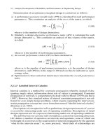
The process requires a press with heated platens or preferably heating in
the mold. Basically a two-part mold is used (Figure 4.1) (Chapter 17).
The female or cavity part of the mold, when using a molding com-
pound, is usually mounted on the lower platen of the press, while the
male or plunger part is aligned to match the female part and is attached
to the upper platen (Figure 14.1). If a plastic impregnated material
(sheet, mat, etc.) is used the female or cavity part of the mold is usually
mounted on the upper platen of the press, while the male or plunger
part is aligned to match the female part and is attached to the bottom
platen (Figure 14.1).
The plastic molding material is weighed out and is usually preheated
before charging (transferring) to the cavity part of the heated mold.
After charging the mold, the press is closed bringing the two parts of
the mold together. This allows the molding material to melt and flow
through filling the cavity between the two parts of the mold, and at the
same time pushing out any entrapped air ahead of the melt so as to fill
the mold cavity completely. After holding the plastic in the mold for the
time specified for a proper cure under the required temperature and
pressure, the pressure is released, the mold opened, and the solid molded
plastic part discharged. In a modern high-speed automatic compression
press all the operations are performed automatically.
The necessary preheating and mold heating temperatures and mold
pressure may vary considerably depending upon the thermal and
theological (refers to the deformation and flow properties of the plastic)
properties of the plastic (Chapter 1). For a typical compression molding
Ta!)~e ~ 4_~
Cor~par!qg comp~essi3n m3!ded pro=erties with o-_her ;rocess~s
Compressive Tensile Fle~,,ral
Reintnrccm~n t Stremgl~ Modulus Strength
l'r~e~ wl~, MPa kJt C~Pu lIP p=i M]~
k~i
Heat
Tensile Impact Distortion
Di~-'~ric
Strength S~rength at l.SMPa St~ngth
MPa ksi J/m ft. Ibf/fl C |: kV/cm kVfin,
f~lycJt~r
SMC
Comp~h~ 25-~ ~
F]larnen~ 3(~&2
sLms,.~
winding epoxy
P~ttr~
~on, ~ ~as~
mat-
~olye~rer
IOt~i71) 15-25 5.'~-|20.L~-|.~ ItO [~,Xl |6 2H ~) t2()
|01) 211) |~4-~1 11-|7 1.6-2~ 120-2|0 I1¢ ~! 55-1,40
!~0 2]0 t5 3~ 6.2-]4 ~Lg ~O 7(I 280 IO.~ 170 2t0
9-IX 210-640 48-]44 175-~)5 3.~, 400 ~) I~() ~K)-4(Xl
8-20 L'~)-I,I~) ~Xcv-264 20~-2/,/J 4fiO ~O 120-1~') 3(KN~}
25-30 ;30-I,0~) 120-240 175-205 350-400 120-240
3iO-41~ 4.'~ 7n 2X ~2 4.~-9.O 69(~-1~150 i(X),-270 550 I,7(X) ~3-~_~)l~)-32(X) 4~) 72~ |75-20S 350-4(~ 120-[60 3(X) 4(X)
210-480 30-~I) 2~ 4! 4,0.6.0 6~-1,0~0 I00-150 410-1,05,0 60-150 400-3200 540-7"20 205-260 400-500 80-160 2{X) ~O
t
o
3
o
~t
3
o
et
t.o
4~
4~
t
442 Plastic Product Material and Process Selection Handbook
thermoset material preheat may be at 200F (93C) and mold heat and
pressure may be near 250 to 350F (121 to 177C) and 1000 to 2,000
psi (6.9 to 13.8 MPa). A slight excess of material is usually placed in the
mold to insure it being completely filled and this excess is squeezed out
between the mating surfaces of the mold in a thin, easily removed film
known as flash. As shown in Figure 14.2 flash can form in different
positions based on how it is to be removed. Different methods are used
to remove flash such filing, sanding, and/or tumbling. There are systems
where parts arc frozen (dry ice) malting it easier for certain types of
plastic parts to be &flashed.
Figure 14,2 Examples of flash in a mold: (a) horizontal, (b) vertical, and (c) modified vertical
In the case of a thermoplastic, the molding temperature cycle is from
heating to plasticizing the plastic, to cooling in the mold under pressure,
the pressure released, and the molded article removed. When TS is used
the mold need not be cooled at the end of the molding operation or
cycle, as the plastic will have hardened and can no longer flow or distort
(Chapter 1 ).
The molding cycle takes anywhere from a few minutes to an hour
depending upon the type of plastic used and the size of the charge. The
cycle steps are
1 charging;
2 closing the press;
3 melting the plastic;
4 applying full pressure and heat;
5 curing for TSs or cooling for TPs;
6 discharging or ejecting the molded part.
Most of the time is consumed in the cure or cooling stage, while some
of the other stages could take only a few seconds.
14. Compression molding 443
Compression molding was the major method of processing plastics
worldwide during the first half of the last century because of the
development of phenolic plastics (TSs) in 1909. By the 1940s this
situation began to change with the development and use of thermo-
plastics (TPs) in injection molding (IM).
CM originally processed about 70wt% of all plastics, but by the 1950s
its share of total production was below 25%, and now that figure is
about 3% of all plastic products produced internationally. Worldwide
350 million lb/yr arc estimated to be consumed. This change does not
mean that CM is not a viable process; it just does not provide the much
lower cost-to-performance benefit of TPs that are injection molded,
particularly at high production rates. In the early 1900s plastics were
almost entirely TS (95wt%) used in different processes, but that
proportion had fallen to about 40% by the mid-1940s and now is about
10%.
TSs has experienced an extremely low total growth rate, whereas TPs
have expanded at an unbelievably high rate. Regardless of the present
situation, CM is still important, particularly in the production of certain
low-cost products as well as heat-resistant and dimensionally precise
products. CM is classified as a high pressure process. Some TSs may
require higher pressures while others require lower pressures of down
to 50 psi (0.35MPa) or even just contact/zero pressure.
The advantages that keeps the compression process system popular are
due primarily to the simple operation that defines the system. The
heated cavity is filled directly and then pressurized for the duration of
the cure cycle. Examples of advantages arc as follows:
1 Tooling costs are low because of the simplicity of the usual molds.
2 Little material is wasted since there are usually no sprucs or runners
[when not compared to runnerless injection molding (Chapter 4)].
3 TSs when compared to TPs are not subject to retaining internal
stresses after being cured.
4 Mechanical properties remain high since material receives little
mastication in the process and when using reinforcements they are
literally not damaged or broken.
5 Less clamping pressure required than in most other processes.
6 Capital equipment is less costly.
7 Wash-action erosion of cavities is minimal and mold maintenance is
low since melt flow length is short.
444 Plastic Product Material and Process Selection Handbook
Limitations of the method include"
Fine pins, blades, and inserts in the cavity can become damaged as
the press closes when cold material is used in the cavities.
Complex shapes may not fill out as easily as by the transfer or
injection molding processes.
Extremely thick and heavy parts will cure more slowly than in trans-
fer or injection molding, but preheating preforms or powder can
shorten these cures.
Thcrmosets with their low viscosity will produce flash during their
cure that has to be removed.
Mold
Three general types of molds are used for CM. In the positive mold
(Figure 14.3a) all the material is trapped in the mold cavity. The pressure
applied compresses the material into the smallest possible volume. Any
variation in the weight of the charge will result in a variation in part
thiclmess. In multicavity molds, if one cavity has more material than the
others, it will receive proportionately greater pressure. Multiple cavities,
therefore, can result in density variations between parts if loading is not
done with some degree of precision control. 1, 278-284
A flash mold (Figure 14.3b) has a narrow land or pinchoff area around
the cavity. Material is compressed in the cavity to a density that will
match the force applied. Excess material escapes across the pinchoff line
as flash. Immediately beyond the pinchoff line, the surface is relieved to
allow the flash to fluff out rather than to cure in a hard skin that would
adhere tightly to the metal surface.
The semipositive mold (Figure 14.3c) is by far the most popular. It
combines the best features of the positive and the flash molds. Since its
design includes a plastic material well of larger diameter, with a tight
fitting force above the cavity, the material is trapped fairly positively and
the plastic is forced to flow into all corners of the cavity. As the material
picks up more heat and becomes fluid, it escapes between the force and
cavity sidewalls as flash, allowing the force to scat on the land area.
Clearance between the sidewall of the cavity and the OD of the force
generally is about 0.004 in. Variation in this clearance will vary the
density of the molded part. The gases that are released from curing
certain TS plastics, as well as the air in the cavity, must be allowed to
[:igure 1 4,3 Exampie of mn : b/pes: I:a) positive :omF, ressioq "note, (b) flas k compression mold, and (c} semipos[tiv¢ compression mold
4~
3
m,
o
-,I
=I
o
=,-
4~
4~
446 Plastic Product Material and Process Selection Handbook
escape. They will, in some cases, filter through the flash and/or the
clearance around the ejector pins. Usually vents are also included in the
mold to permit release of these gases. When processing TPs there
should not be a problem in flash occurring. However air in the cavity
has to be released so vents in the mold are used that is a take off of
injection molding molds. 3
The TS gases are more of a problem with urea and melamine than with
phenolic. To ensure they do not become entrapped in the molding
material during compression molding, and in turn weaken the molded
part or cause surface blemishes, it often is advisable to open the mold to
allow gases to escape. This is called breathing or bumping. It amounts
to sufficient reduction in clamp pressure to allow the pressurized gases
to blow their way out, and/or sufficient opening movement to create a
slight gap for trapped gases to escape effortlessly.
To aid in controlling the thickness of molded parts and/or support the
pressure loads put on sections of a mold, lands in the mold are used.
Examples of lands are shown in Figure 14.2. Figure 14.4 shows the
land locations used in a mold that supports the split-wedge in the mold.
Figure 14,4
Example of land locations in a split-wedge mold
14 9 Compression molding 447
When plastics, particularly compounds, prepregs, and sheet materials
that are filled with reinforcements such as glass fibers, the matting
edges of the mold cavity require special treatment (Chapter 17). The
target is to ensure proper and clean-cut edges of the parts. The materials
of construction can overlap the edges prior to or during molding. 3
Machine
The CM machines are usually referred to as compression presses. They
are primarily hydraulic or, in limited use, pneumatic. Either of these
systems can have the usual straight lockup system or toggle lockup
system (Chapter 4). These presses may be either down-acting or up-
acting. The down-acting type is used for the fully automatic
compression presses so that the lower mold half is at a fixed height to
align with the material feeder and molded product stripper tables.
Different actions in molds occur such as using ejector pins to remove
molded parts from their cavities. Side actions of molds may be required
to remove parts that have undercuts. Other actions may be required such
as unscrewing threaded parts, including inserts, and so on (Chapter 17).
The presses are available in all sizes to meet the many different require-
ments for parts to be molded. These differences include short to long
curing cycle times, small to large parts requiring different pressures
(clamp tonnages), and so on. They range from less than a
1/2
to
thousands of tons with platens 4 by 4 in. to at least 10 by 20 ft. The
usual press has two platens and others have up to at least 30 platens that
can simultaneously mold flat sheets or other products. There are presses
with shuttle molds and those that have a series of individual presses (3
to at least 25) that rotate providing the TS plastic to complete its curing
cycle, permit ease of including inserts, etc. Presses usually have their
platens parallel to each other and there are those that open like clam
shells referred to as book type. Other processes reviewed in this book
provide examples of these type presses to fabricate by their respective
methods (Chapters 4, 12, 15, and 16).
In use arc stamping compression molding presses. Plastic used can be
TS shcct molding compounds (SMCs) and stampablc rcinforccd
thcrmoplastic sheet (STX) material (STX is a rcgistcrcd tradcnamc;
Azdcl Inc., Shelby, NC). It is usually composcd of a glass fiber-
thermoplastic RTP (Chaptcr 15).
448 Plastic Product Material and Process Selection Handbook
Plastic
; i; ;.~7~ - .
Different TS plastics are used such as phenolics, TS polyesters, DAPs,
epoxies, ureas, melamines, and silicones, all with their own processing
requirements and performance molded properties based on their
compositions. [Note there are TS and TP polyesters (Chapter 2)]. Also
used arc TPs. TSs arc used primarily in CM and TPs in injection molding,
extrusion, blow molding, etc. In this review the emphasis is on TSs,
which have different processing characteristics to TPs (Chapter 1).
Materials can be unreinforced or reinforced/filler compounds, sheet
molding compounds (SMC), bulk molding compounds (BMC), prepregs,
preforms or mats with liquid resins, etc. With TSs, they cure via A-B-C
stages that identify their heat cure cycle. A-stage is uncured (in the form
received from a material supplier), B-stage is partially cured with heat,
and C-stage is fully cured. A typical B-stage is TS molding compounds
and preprcgs, which in turn arc processed to produce C-stage fully cured
plastic material products in compression molds. TSs when heated go
through crosslinking chemical reactions to produce hard or rigid plastic
product. TPs during molding go through a melting stage when heated
followed with a hardening stage when cooled (Chapter 1).
An example of very popular CM materials are bulk molding compounds
(BMCs); in Europe they are called dough molding compounds
(DMCs). They are formulated from different percentages of TS
polyesters filled with glass fibers of lengths up to 1/2 in (13 mm) and
fillers. The BMCs flow easily and provide high strength (Chapter 15).
Also popular as CM molding materials are the TS vinyls used for
phonograph records, etc. TP vinyls are crosslinked to turn them into
TS vinyls (Chapter 1).
Very soft flowing TSs are required for molding around very delicate
inserts. Large quantities of electronic components such as resistors,
capacitors, diodes, transistors, integrated circuits, etc. arc encapsulated
with such soft-flowing TS compounds. Principally used are epoxies by
compression molding (and transfer molding). Silicone molding com-
pounds are used occasionally where higher environmental temperatures
are required of the encapsulated part that can be exposed up to 500F
(260C) or more. TS polyester compounds, that are less expensive than
epoxies, or silicones that are more expensive, arc also selected when
their requirements suffice (Chapter 2).
In the use of preform and mat-reinforced molding, the plastic may be
added either before or after the reinforcement is positioned in the
cavity. The preform can be a spray-up of chopped glass fibers deposited
14. Compression molding 449
on a shaped screen with a minimum of plastic binder (about 1 to 5wt%
of resin compatible with the molding resin). Different techniques are
used to provide desirable surfaces (Chapter 15).
Depending on the type of material used, and the size and thickness of
the product, different temperatures, pressure, and time schedules are
used. Temperatures range from about 200 to 350F (93 to 177C).
Pressurewise, the range is from about 1,000 to 2,000 psi (6.9 to 13.8
MPa). Time cycles can range from less than 1 minute to many minutes.
The process called matched-die molding, generally identifies CM
operating at the lower pressures.
Polytetrafl uoroethylene
Processing the usual thermoplastics (PE, PP, PVC, PS, etc.) sets up no
special technique. However certain TPs such as polytetrafluoro-
ethylenes (PTFEs) require special techniques because they do not have
the usual easy melt flow. CM is used to fabricate cylindrical billet,
molding, or sheet shapes of PTFE. This type of CM is also called
isostatic compression molding. As an example electric-grade tapes are
sldved from billets with a wall thickness of 75 to 100 mm. The granular
plastic goes through the three stages of preforming, sintering (heating)
and cooling.
The large quantity of plastic and the length of time needed to produce
a shape requires careful attention to factors that affect fabrication such
as the handling and storage of the plastic. High temperature storage of
granular PTFE can lead to compaction during handling. Plastic should
be conditioned at temperatures of 21 to 25C (70 to 77F) before molding
to reduce clumping and ease handling. Dew point conditions should be
avoided to prevent moisture from condensing on the cold powder that
will expand during sintering and crack the molding. Molding below 20C
(68F) should be avoided because PTFE will undergo a 1% volumetric
change at a transition temperature of 19C (66F).
Preforms molded below 20C can crack during sintering. Sintcring is the
process of holding the fusible pressed powder part (PTFE, nylon, etc.)
at a temperature just below its melting point for a specific time period.
Powdered particles are fused (sintered) together but the mass as a
whole does not melt. PTFE is an excellent thermal insulator that is
about 2,000 times less than copper. The most common way of
delivering heat to the preform is by circulation of hot air. A large
volume of air has to be recirculated because of its low thermal capacity.
450 Plastic Product Material and Process Selection Handbook
After being removed from the mold it is heated to a higher temperature
to completely fuse the sintered material resulting in property increases
(tensile strength, etc.), ductility, and usually density. Good temperature
control is critical to achieving uniform and reproducible part
dimensions and properties. Sintering of the preform takes place in an
oven where massive volumes of heated air are circulated. Initial heating
of the preform leads to thermal expansion of the part. After PTFE
melts, relaxation of the residual stresses occur where additional recovery
takes place and the part expands. The remaining air begins to diffuse
out of the preform after heating starts. The adjacent molten particles
begin to coalesce slowly; usually hours are required because of the
massive size of PTFE molecules. Fusion of the particles is followed by
elimination of the voids, where almost no air is left.
Cooling at a controlled rate after sintering takes place ensures proper
crystallization and annealing of the plastic. Properties of PTFE (similar
to other semicrystalline polymers) are controlled by the crystalline
phase content of the part (Chapter 1). To remove residual stresses in
the plastic, annealing is used, which takes place after a period of time.
The final crystallinity of the part depends on the annealing temperature.
A part which is annealed below the crystallization temperature range
[<300C (<572F)] will only undergo stress relief. Annealing at a
temperature in the crystallization range [300 to 325C (572 to 612F)]
results in higher crystallinity. The result is higher specific gravity and
opacity in addition to stress relief.
Processing
Processing conditions such as temperature, pressure, and molding cycle
differ for the different plastics. There exists a wide range of flow
characteristics with the different plastics and also within a specific plastic
when they have different compositions. These molding compounds are
mixtures of constituents, usually of different size and shape. The
compounds themselves present the greatest number of variables that
must be understood and properly applied. The processing conditions
with TSs as well as TPs ultimately effect mechanical, chemical,
electrical, aesthetic, and other properties.
Many TS compounds are heated to about 300 to 400F (149 to 204C)
for optimum cure; but can operate as high as 1200F (650C). Over
heating any materials could degrade their performance or could cause
them to solidify rapidly before the mold cavity is completely filled.
14 9 Compression molding 451
Preheating is often used to reduce the molding cycle. It can aid in
providing even heat through the material and can cause a more rapid
rise in heat than occurs in the mold cavity. A warm surface plate,
infrared lamps, hot-air oven, or screw/barrel preheatcr can accomplish
preheating. The best and quickest method is high-frequency (dielectric)
heating.
Preheating is usually carried out at 150 to 300F (66 to 149C) followed
by quick transfer to a mold cavity. The actual heat depends on the
material, the heater capability, and the speed of transfer. Circular
prcforms are normally used with dielectric heaters so they can be
rotated to obtain uniform heating. Pills of compressed compound are
used to produce preforms to facilitate handling, reduce the bulk factor
in the cavity, and control the uniformity of charges for mold loading.
Preforms can also be the shape of the mold cavity.
Compared to other processes, particularly injection molding (IM) for
shaping plastics, CM is fairly labor-intensive even if it is automated.
However it requires lower capital investment. Molding cycles for CM
arc generally longer than for IM. If the material used is preheated or
preplasticizcd before it is placed in a mold cavity, molding cycles may bc
comparable to IM. When CM flash formation in the molds occur, their
viscosity during the melting action resembles that of water. Techniques
can be used to significantly reduce flash by modifying the mold design.
To aid in reducing cycle time there are molded parts that can finish
their cycle in a fixture. After a molded product is removed from the
cavity it is still hot and the material is not fully rigid. Any internal
stresses in the material may therefore cause the shape of the product to
change while it is cooling. Where close tolerances are required and
especially where products have thin sections, dimensional accuracy can
be met by placing the hot, molded product on a fixture near the press
that will hold it until it has cooled.
To improve properties such as mechanical, thermal, and dimensions of
certain molded TSs, also certain TPs, they arc exposed to a postcure.
The part is literally baked in an oven. Experience or a material supplier's
recommended times and temperature profiles required to enhance
properties arc used. Baiting also improves creep resistance and reduc-
tion in stresses. This postcuring is also used with certain TPs after IM
or extrusion to improve their performance.
Postcuring heat is usually below the actual molding heat. It is usually
performed in a multistage heat cycle. The reinforcement system of the
compound will dictate heating cycles. Products molded from com-
pounds using organic reinforcements arc postcured at lower heats than
452 Plastic Product Material and Process Selection Handbook
those using glass and mineral reinforcements. Products of uneven thick-
ness will exhibit uneven shrinkage. This shrinkage effect is included in
the mold design.
eater
There are many heat choices available and a wide choice of temperature
controls as there is with other fabricating processes. They range from
simple mechanical thermostats to solid state units with PlD control, to
microprocessors that are proportional, programmable, and self-tuning
(Chapter 3 ).
Electrical heating, through the use of heater coils, strips, or cartridges,
is the most popular method. Higher temperatures for faster cycles are
easily obtained. Recognize that electric mold heating is only as fast as
the wattage put into it. It is a cleaner system than steam that was used
many decades ago.
Steam heat provided the fastest recovery time of any system because of
the oversize source available in the boiler room. It offered a uniform
mold temperature, as do all liquid systems, but is limited to about 350F
(177C) maximum. Steam heat is also messy and requires good main-
tenance, or rusty pipes and leaks become all too common. Steam controls
and the accompanying valves are expensive and many are not dependable.
Hot oil heat offers the benefits of higher temperatures from a liquid
system. It results in probably the most uniform mold temperatures
primarily because the fluid is being constantly circulated. Recovery
time, however, is limited to the total heat capacity designed into the
circulating unit.
High pressure water systems are also available that heat by continuously
circulating hot water. The advantage is less corrosion than steam since
the oxygen is not replenished in the closed circuit. Also, temperatures
are more uniform than steam because, like hot oil, it is a dynamic
system. These systems are expensive and costly to maintain.
Gas flames have been used on rotary presses. Gas also has been used
with some exotic materials requiring very high temperatures [over
2000F (1,093C)].
Automation
A variety of feeders have been designed to move the molding material
into the mold, and special strippers built to remove the molded parts.
All of these have the common goal of faster, more efficient, and
14 9 Compression molding 4,63
automatic production. The feeders include feeding cold powder
through tubes from overhead hoppers, reciprocating, feed boards, etc.,
and the feeding of preheated, partially or fully plasticated material from
infrared heated hoppers, RF heating units, or screw plasticators.
Automatic strippers have included many combinations of air blow-off,
metal combs, and catch trays or chutes. Programmable robots are used
for this type of work. These sophisticated units are also used to add
inserts before loading the mold.
Recently all of the temperature, pressure, and time controls have been
replaced with a single microprocessor-based controller. A number of
these are available and they allow for complex pressure and temperature
curves to be programmed with multiple soaking levels and variables
that can be chosen. Built-in memories recall previous programs and
cassettes can store them on the shelf. Interfaces can connect with a
central host computer for data collection or actual machine setup and
supervision. The result is more flexible, more exacting, and easier to
control modern molding equipment (Chapter 3).
Transfer Molding
Shaw of Pennsylvania developed this plastic transfer molding process
during the 1930s. It is a method of compression molding, principally
thermoset plastics. Heat and pressure in a transfer chamber (pot) first
soften plastic. After the heating cycle it is forced by a ram at high
pressure through suitable sprues, runners, and/or gates into a closed
mold to produce the molded part or parts using one or normally two or
more cavities (Figure 14.5). Usually dielectrically preheated circular
preforms are fed into the pot. Plastic remaining in the transfer chamber
after mold filling is called a cull. Unless there is slight excess in this
chamber, one cannot be sure that the cavity(s) was completely full.
Since the plastic entering the cavities is melted it requires less force
to
fill the cavities than compression molding With conventional CM there
is more force in the cavities as the solid plastic is melted. The result is
that more intricate parts can be molded as well as encasing intricate
devices such as electronic.
Compression-Injection Molding
Usually called injection-compression molding (ICM). Details are in
Chapter 4. The essential difference when compared to IM lies in the
manner in which the thermal contraction in the mold cavity that occurs
during cooling (shrinkage) is compensated. With conventional injection
454 Plastic Product Material and Process Selection Handbook
Figure 14.5 Schematic of transfer molding
molding, the reduction in material volume in the cavity due to thermal
contraction is compensated basically by forcing in more melt during thc
pressure-holding phase. By contrast with CIM, a compression mold
design is used where a male plug fits into a female cavity rather than the
usual fiat surface parting line mold halves for IM
Hydrostatic Compression Molding
Hydrostatic molding is a suitable alternative to compression molding
techniques for the production of plastics that do not have the usual
melt flow behavior, such as previously reviewed in the Plastic section for
polytetrafluoroethylene.
REINFORCED
PLASTIC
Overview
Industry continues to go through a major evolution in reinforced plastic
(R P) structural and semi-structural materials. RP has been developed to
produce an exceptionally strong and corrosive material. The RP products
normally contain from 10 to 40wt% of plastic, although in some cases
plastic content may go as high as 60% or more (Figures 15.1 and 15.2).
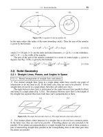
Figure I 5~ 1 Effect of matrix content on strength (F) or elastic moduli (E) of reinforced plastics
Figure 15~2
Properties vs. amount of reinforcement
456 Plastic Product Material and Process Selection Handbook
RPs, also called plastic composites or composites, are tailor-made
materials which provide the designer, fabricator, equipment manufacturer,
and consumer, engineered flexibility to meet different properties, environ-
ments, and create different shapes. They can sweep away the designer's
frequent crippling necessity to restrict performance requircmcnts of
designs to traditional monolithic materials. The objective of a plastic
composite is to combine similar or dissimilar materials in order to develop
specific properties related to desired characteristics. Composites can be
designed to provide practically any variety of characteristics. For this
reason, practically all industries use them. Economical, efficient, and
sophisticated parts arc made, ranging from toys to bridges to reentry
insulation shields to miniature printed circuits to missiles.
Almost any thermosct or thermoplastic matrix (resin/plastic) property can
be improved or changed to meet varying requirements by using reinforce-
mcnts. Typical resins used include polyester (thcrmosets and thermo-
plastics), phenolic, epoxy, silicone, diallyl phthalate, alkyd, melamine,
polyamide, fluorocarbon, polycarbonate, acrylic, acctal, polypropylcne,
ABS copolymcr, and polyethylene (Chapter 2). Reinforced thcrmoscts
(RTSs) predominate for the high performance applications. However
there has been successful concentrated effort to expand use of reinforced
thermoplastics (RTPs) in the electronic, automotive, aircraft, underground
pipe, 1 appliance, camera, and other high performance products. 49,
285-288,
439
Result is that over 50wt% of all RPs arc thermoplastic types, principally
injection molded, using short and long glass fibers (Chapter 4).
Fiber strengths have risen to the degree that 2-D and 3-D RPs can be
used producing very high strength and stiff RP products having long
service lives. Products in service have over a half-century of indoor and
outdoor service. RPs can be classified according to their behavior or
performance which varies widely and depends on time, temperature,
environment, and cost. The environment involves all kinds of conditions
such as amount and type of load, weather conditions, chemical resistance,
and many more. Directly influencing behaviors or performances of RPs
involve type of plastic, type of reinforcement, and process used. These
parameters arc also influenced by how the product is designed. Figure
15.3 and Tables 15.1 to 15.3 provide information on properties,
processes, and characteristics of RPs.
Definition
A precise definition of reinforced plastics can be difficult (or impossible)
to formulate because of the scale factor. At the atomic level all elements
1 5.
Reinforced plastic 457
50
I
i I I
[
I
4o-
I
T I
X
ao- i
._
_m
Z
o
20
-= = i /Titanium
:E
! z
Aluminum
1~
!/'G,~
I /
l/Spruce , , I
0 1 I ,
0 2 4 6 8 10
Specific gravity
Figure 15.3 Modulus of different materials can be related to their specific gravities with RPs
providing an interesting graph
Tabte 15, I
Review of a few processes to fabricate RP products
Compression Molding
Injection Molding
Flexible Plunger Marco Process
Flexible Bag Molding Pultrusion
Laminate
Hand Lay-Up
Vacuum Bag Molding
Vacuum Bag Molding and Pressure
Pressure Bag Molding
Autoclave Molding
Autoclave Press Clave
9 Reactive Liquid Molding
Reinforced Resin Transfer Molding
Reinforced Rotational Molding
Squeeze Molding
SCRIMP Process
Soluble Core Molding
Lost-Wax Process
Wet Lay-Up Spray-Up
Bag Molding Hinterspritzen
Stamping
Contact MOlding Cold Forming
Filament Winding
Fabricating RP Tank
Comoform Cold Molding
Tabie
15.2
Plasdc
-xam;les cf reinf01ccd :htrrn0plastZc
p,operties
Impa(:t
Sb"engdt,
Glas~ T¢~ Te rzsR.e Flexur~ Fl,miur~ Cnmpr~sFce ]Lzod
Fiber
Sl~=ciflc
S Ir~n~b. Tensile ,=,iodutus Strength Slodulus Strength
,NOIC hL~N:J¢
Conlent, Gr =Vii3~,
!MPag
rdlongalion
tGPab
L~tPa), (6Pa), lMPah t J/rob
I'W% %) D 7'9,g O ~ (%L D 638 D ~ D 790 O ~ O 6"95 O 2,56
-~BS t0 i. [0 &5
3.0
4.6 102 4.5 $3 64
":'0 12.2 76
2.0 S.l 107 4.9 g7 59
39 E ~ 90 l.~' 6.3 116 6.4 I(34 .53
A~e|af 19 ! 54 72 2.4 6.6 107 6.1 69 53
30 ] 63 83 2 O 7.7 114 72 81 43
N).lc n "6 15, ] 25 104 4.0 5.9 159 5.4 97 80
3,g 1.$7 1E6 3 O 72 200 6.9 166 117
Nylon 6-~ I-?, ]
23 B7
4 O 6.2
173 4-5 93 53
30 1.37 173 3 C, 9.0 23S 9,0 I8fi 107
N.y'| on E,~I2 30 1.30 135 4.0 8.3 193 7.6 138 117
F'c-~',~a~T'.~te
l0 126 83 9,0 5 2 I I0 4.1 97 107
30
1.43 121
2.0 8.6
141
6.9
117 128
Poh._'es[er=TP" 30 t.52 131 4.0 8,3 193 7.9 124 96
Po~ethyIe.ne 19 I_04 36 4.0 2.5 46 2-5 35 75
30 1.18 59 3.0 5.0
89 4.9 41 91
Polyphenv~er~e 40 i ,64 152 30 14,1 255 13.0 145 80
su]6de
Polv]aro~yle~te 10 0.98 43 4.0 2-5 54 2.4 41 43
20 t.I)4 4.$ 3.0 3.7 57 3.6 45 59
1.12
47 Z .0 4.4 63 43 47 69
Pob~p, ro py~er~
10
0,~8 50-59 4.9 3,7 72-94 3.5 43 M ~-75
Potysty/'ene
High hea, l co- 2:0 122. 90 12 83 131 7.9 110 59
pob'mer
High heal let-
30
t=2S 83 1.8
6-5
tz3 5.7 76 80
polymer
Polysulfone zo 1.38 97
2.5
6.0 138 5.9 124
40 155 12.4 1.5 11.6 173 10.7 13.8 80
Pobe'u re thane
1i~
! 2Z 33 48 3
0.7
43 0.6 35 747
F~/C 20 158 ~ 3.CI 0.8 145 6.9 $3 80
SAN 20 12Z 100 l.S
8.6
131 7.6 121 64
3~
135 I10 I.¢
1D.4
155
93 45
53
4~
0~
¢B
t~
~e
J.
¢3
"O
B
¢3
fll
¢
"ll
¢3
rD
t/t
t/l
i/l
r~
S"
:3
-r
O
O
15. Reinforced plastic 459
Table 15.3
Examples of properties and processes of reinforced thermoset plastics
ii i i ii iii iiiiii i i[i iiiiii i iiiii iiij iii ii iii iiiiiii iiiiii1[11 iiij i i i iiii iiiiiiiii iiiiiiiiii ii iii ii ii i i iiiiii
Them~oset Pioperty Process
Polyesters
Epoxies
Simplest, most versatile,
economical,
and most widely used
family of
resins; good electrical properties,
good
chemical resistance,
especially to acids
Compression
molding, filament
winding, hand lay-up,
mat
molding, pressure bag molding,
continuous pultrusion, injection
molding, spray-up, centrifugal
casting, cold molding,
encapsulation, etc.
Excellent mechanical and ~ihesion t~vpci~ies
Compression molding,
filament
dimensional
stability, chemical winding, hand lay-up,
resistance (especially to alkalis), continuous pultrusion,
low water absorption, self- encapsulation, centrifugal casting
extinguishing (when
halogenated), low shrinkage,
good
abrasion resistance
Compression molding, continuous
lamination, high pressure process
l~.molics
Good acid resistance, good
electrical
properties (except arc resistance),
high heat resistance
Silicones
Highest heat resistance, low water
absorption, excellent dielectric
properties, high arc resistance
Melamines Good heat resistance, high impact Compression
molding
strength
Diallylgphth~dates Good electrical insulation, low water
absorption
i iiii iiiii i iiiiiiiiiiiiiii ii i ii ii ii
Compression molding, injection
molding,
encapsulation
Compression
molding
are composites of nuclei and electrons. At the crystalline and molecular
level materials arc composites of different atoms. And at successively
larger scales materials may become new types of composites, or they
may appear to be homogeneous (Chapter 1).
Wood is a complex composite of cellulose and lignin; most sedimentary
rocks arc composites of particles bonded together by natural cement;
and many metallic alloys arc composites of several quite different con-
stituents. On a macro scale these are all homogeneous materials.
In this review, RPs arc considered to be combinations of materials
differing in composition or form on a macro scale. But all of the
constituents in the plastic composite retain their identities and do not
dissolve or otherwise completely merge into each other. This definition
is not entirely precise. It includes some materials often not considered
to be composites. Furthermore, some combinations may be thought of
as composite structures rather than composite materials. The dividing
line is not sharp and differences of opinion do exist. Regardless the
name composite literally identifies thousands of different combinations
with very few that include the use of plastics. In using the term
composites when plastics are involved the more appropriate term is
plastic composites or just RP.
460 Plastic Product Material and Process Selection Handbook
Many combinations of reinforcements and plastics are used by industry
to effect a diversity of performance and cost characteristics. These may
be in layered form, as in typical melamine-phenolic impregnated paper
sheets, and polyester impregnated glass fiber mat or fabric, or in
molding compound form, as in glass or cotton-filled polyester, phenolic,
or urea molding compounds. Inline compounding and injection molding
thermoplastics with long glass fibers can be performed. Glass fibers
(rovings, etc.) can be fed into a single- or twin-screw extruder where
the TP is melted. It cuts the reinforcement and provides an excellent
mix. All these resulting composites have many properties superior to
the component materials. 4, 22,173,210
Basically a plastic composite is the assembly of two or more materials
made to behave as a single product. Examples include vinyl-coated
fabric used in air mattresses or laminated metal bonded together with a
plastic adhesive used in helicopter blades. The RP type of composite
combines a plastic with a reinforcing agent that can be fibrous,
powdered, spherical, crystalline, or whisker, made of organic, inorganic,
metallic, or ceramic material. To be structurally effective, there must be
a strong adhesive bond between the resin and reinforcement.
Fibrous Composite
The large-production reinforcing agent used today is primarily glass.
Other fibers include cotton, cellulosic fiber, sisal, polyamide, jute,
carbon, graphite, boron, whiskers, steel, and other synthetic fibers, l~ 12,
289-291,
466 They all offer wide variations in composition, properties,
fiber orientation/construction, weight, and cost (Tables 15.4 and 15.5
Table t 5~4
Properties of fiber reinforcements
Type of fiber
reinforcement
Glass
E Monofilament 2.54
S Monofilament 2.48
Boron (tungsten
substrate)
4 mil or 5.6 mil 2.63
Graphite
High strength 1.80
High modulus 1.94
Intermediate 1.74
Organic
Aramid 1.44
Tensile
Tensile
elastic Specific
Density strength Specific modulus
elastic
Specific lb./in) 103 psi strength 106 psi modulus
gravity (g/cm 3) (GPa) 10 ~ in. (GPa) l0 s in,
0.092 (2.5) 500 (3.45) 5.43 10.5 (72.4) 1.14
0.090 (2.5) 665 (4.58) 7.39 12.4 (85.5) 1.38
0.095 (2.6) 450 (3.10) 4.74 58 (400) 6.11
0.065 (1.8) 400 (2.76) 6.15 38 (262) 5.85
0.070 (1.9) 300 (2.07) 4.29 55" (380) 7.86
0.063 (1.7) 360 (2.48) 5.71 27 (190) 4.29
0.052 (1.4) 400 (2.76) 7.69 18 (124) 3.46
15-Reinforced plastic 461
and Figure 15.4). With the performance to weight advantages of carbon
fiber the 200 to 250 passenger Boeing 7E7 high speed jet (mach 0.85)
light weight commercial airplane will have the majority of its primary
structure (wings, fuselage, etc.) made of carbon reinforced composites. 465
Table 1 5~5 Examples of different carbon fibers
Figure I 5~4 Short to long fibers influence properties of RPs
Glass fibers, the most widely used at over 90wt% of all reinforcements,
arc used in many forms for producing different commercial and
industrial products, also for parts in space, aircraft, surface water and
underwater vehicles. The older and still popular form is E-glass. S-glass
produces higher strength properties (Table 15.4). Other forms of glass
fiber exist that meet different requirements. E-CR glass fibers are
boron-flee E-glass; combines electrical and mechanical properties of E-
glass with corrosion resistance. 44~
Materials in the form of fibers are often vastly stronger than the same
materials in bulk form. Glass fibers, for examples may develop tensile
strengths of 7 MPa (1,000,000 psi) or more under laboratory
conditions, and commercial fibers attain strengths of 2,800 to 4.8 MPa
(400,000 to 700,000 psi), whereas massive glass breaks at stresses of
about 7 MPa (1000 psi). The same is truc of many other materials
whether organic, metallic, or ceramic.
Acceptance and use of nonwoven fabrics as reinforcement of structural
plastics continues to increase. Only with nonwoven fiber sheet
462 Plastic Product Material and Process Selection Handbook
structures can the full potential of fiber strength be realized. 427 Great
advances have been made developing new fibers and resins, in new
chemical finishes given to the fibers, in methods of bonding the fiber to
the resin, and in mechanical processing methods. Nonwoven fabrics are
inherently better able to take advantage of these developments than are
woven sheets.
Strength of commercial reinforced plastics is far below any theoretical
strength. Ordinary glass fibers are three times stronger and stiffer for
their weight than steel. Nonwoven glass fiber structures usually have
strength about 40 to 50% below that of woven fabric lay-ups. But in
special constructions, properly treated fibers have produced laminates as
strong as the woven product, better in some cases.
Reinforced plastics arc usually applied as laminates of several layers.
Many variables are important in determining the performance of the
finished product. Some of the important ones are: orientation of plies
of the laminate, type of resin, fiber-resin ratio, type or types of fibers,
and orientation of fibers.
Nonwoven fabrics are fibrous sheets made without spinning, weaving,
or l~itting. They include felts, bonded fabrics, and papers. The inter-
locking of fibers is achieved by a combination of mechanical work,
chemical action, moisture, and heat by either textile or paper making
processes.
Still stronger and stiffer forms of fibrous materials are the unidirectional
crystals called whiskers. 1 Under favorable conditions crystal-forming
materials will crystallize as extremely fine filamentous single crystals a
few microns in diameter and virtually frcc of the imperfections found in
ordinary crystals. Whiskers are far stronger and stiffer than the same
material in bulk form.
Fine filaments or fibers by themselves have limited engineering use. They
need support to hold them in place in a structure or device. This is
accomplished by embedding the fibers in a continuous supporting matrix
sufficiently rigid to hold its shape, to prevent buckling and collapse of the
fibers, and to transmit stress from fiber to fiber. The matrix may be, and
usually is, considerably weaker, of lower elastic modulus, and of lower
density than the fibers. By itself it would not withstand high stresses.
When fibers and matrix are combined into a composite, a combination of
high strength, rigidity, and toughness frequently emerges that far exceed
these properties in the individual constituents.
Polyamide (nylon) reinforcements can be in fabric form to provide
excellent electrical grade laminates for conventional industrial use. Type
15. Reinforced plastic 463
used has low water absorption, good abrasion resistance, and resistance
to many chemicals.
Carbon and graphite fibers are made by the pyrolysis of certain
naturally occurring and man-made fibers, such as regenerated cellulose
(rayon) fibers. A wide range of physical, mechanical and chemical
properties may be obtained dependent on amount of dehydration. This
product is one of the most structurally efficient reinforcements. Unlike
any other reinforcement, it retains its 2,800 MPa (400,000 psi) tensile
strength when tested up to a temperature of 2700 C (4800F).
Boron in high modulus and strength properties is available with this
type of fiber. A vapor deposition process is the principal method to
produce boron filaments, using 1/2 mil tungsten wire as a plating
substrate.
Aspect Ratio
The ratio of length to diameter (L/D) or length to thickness (L/T) or
major to minor axis of a fiber or other material is the aspect ratio. These
ratios have a direct influence and can be used in determining the
performance of RPs. High values of 5 to 10 provide for high strength.
Theoretically, with proper lay-up the highest performance plastics could
be obtained when compared to other materials. 427
Laminar Composite
Combining layers of materials into a laminated composite
is
an ancient
art, as illustrated by Egyptian plywood, Damascus and Samurai swords,
and medieval armor. There are many reasons for laminating; among
them are superior strength, often combined with minimum weight;
toughness; resistance to wear or corrosion; decoration; safety and
protection; thermal or acoustical isolation; color and light transmission;
shapes and sizes not otherwise available; controlled distortion; and
many others.
Many processes involving temperature fluctuations are made self-regu-
lating by employing laminates of two metals having different coefficients
of expansion. When a strip of such metal changes temperature, the
different expansivities of the two metals cause the strip to bend, rotate,
or elongate, depending upon its shape. In so doing it can make or break
electrical contacts, control the position of a damper, or perform many
other functions. These bimetals or thermostat metals are servo-
mechanisms; they respond to stimuli from the environment to provide
self-regulating behavior. They have this ability because they are
composites; each metal by itself would not provide this behavior.