Steel Designer''''s Manual Part 13 pdf
Bạn đang xem bản rút gọn của tài liệu. Xem và tải ngay bản đầy đủ của tài liệu tại đây (1.27 MB, 80 trang )
916 Floors and orthotropic decks
4. Pucher A. (1977) Influence Surfaces of Elastic Plates, 5th edn. Springer-Verlag,
Wien.
5. Dowling P. & Bawa A.S. (1975) Influence surfaces for orthotropic decks. Proc.
Instn Civ. Engrs, 59, Mar., 149–68.
6. Cuninghame J.R. (1982) Steel Bridge Decks, Fatigue Performance of Joints
Between Longitudinal Stiffeners. LR 1066, Transport and Road Research Labo-
ratory, Crowthorne, Bucks.
Further reading for Chapter 30
Beales C. (1990) Assessment of Trough to Crossbeam Connections in Orthotropic
Steel Bridge Decks. TRL Report RR 276. Transport Research Laboratory,
Crowthorne, Bucks.
Cuninghame J.R. (1990) Fatigue Classification of Welded Joints in Orthotropic Steel
Bridge Decks. TRL Report RR 259.Transport Research Laboratory, Crowthorne,
Bucks.
Gurney T.R. (1992) Fatigue of Steel Bridge Decks. HMSO, London.
Steel Designers' Manual - 6th Edition (2003)
This material is copyright - all rights reserved. Reproduced under licence from The Steel Construction Institute on 12/2/2007
To buy a hardcopy version of this document call 01344 872775 or go to
F
u
ll
P
age
A
d,
3mm
Bl
ee
d
Chapter 31
Tolerances
by COLIN TAYLOR
917
31.1 Introduction
31.1.1 Why set tolerances?
Compared to other structural materials, steel (and aluminium) structures can be
made economically to much closer tolerances. Compared to mechanical parts,
however, it is neither economic nor necessary to achieve extreme accuracy.
There are a number of distinct reasons why tolerances may need to be con-
sidered. It is important to be quite clear which actually apply in any given case, par-
ticularly when deciding the values to be specified, or when deciding the actions to
be taken in cases of non-compliance.
The various reasons for specifying tolerances are outlined in Table 31.1. In all
cases no closer tolerances than are actually needed should normally be specified,
because while additional accuracy may be achievable, it generally increases the costs
disproportionately.
31.1.2 Terminology
‘Tolerance’ as a general term means a permitted range of values. Other terms which
need definition are given in Table 31.2.
31.1.3 Classes of tolerance
Table 31.3 defines the three classes of tolerances which are recognized in Euro-
code 3.
It is important to draw attention to any particular or special tolerances when
calling for tenders, as they usually have cost implications. Where nothing is stated,
fabricators will automatically assume that only normal tolerances are required.
Steel Designers' Manual - 6th Edition (2003)
This material is copyright - all rights reserved. Reproduced under licence from The Steel Construction Institute on 12/2/2007
To buy a hardcopy version of this document call 01344 872775 or go to
918 Tolerances
Table 31.1 Reasons for specifying tolerances
Structural safety Dimensions (particularly of cross-sections, straightness, etc.) associated
with structural resistance and safety of the structure.
Assembly requirements Tolerances necessary to enable fabricated parts to be put together.
Fit-up Requirements for fixing non-structural components, such as cladding
panels, to the structure.
Interference Tolerances to ensure that the structure does not foul with walls, door or
window openings or service runs, etc.
Clearances Clearances necessary between structures and moving parts, such as
overhead travelling cranes, elevators, etc. or for rail tracks, and also
between the structure and fixed or moving plant items.
Site boundaries Boundaries of sites to be respected for legal reasons. Besides plan
position, this can include limits on the inclination of outer faces of tall
buildings.
Serviceability Floors must be sufficiently flat and even, and crane gantry tracks etc.
must be accurately aligned, to enable the structure to fulfil its function.
Appearance The appearance of a building may impose limits on verticality,
straightness, flatness and alignment, though generally the tolerance limits
required for other reasons will already be sufficient.
Table. 31.2 Definitions – deviations and tolerances
Deviation The difference between a specified value and the actual measured value,
expressed vectorially (i.e. as a positive or negative value).
Permitted deviation The vectorial limit specified for a particular deviation.
Tolerance range The sum of the absolute values of the permitted deviations each side of a
specified value.
Tolerance limits The permitted deviations each side of a specified value, e.g. ±3.5mm or
+5mm -0mm.
Table 31.3 Classes of tolerances
Normal tolerances Those which are generally necessary for all buildings. They include those
normally required for structural safety, together with normal structural
assembly tolerances.
Particular tolerances Tolerances which are closer than normal tolerances, but which apply only to
certain components or only to certain dimensions. They may be necessary
in specific cases for reasons of fit-up or interference or in order to respect
clearances or boundaries.
Special tolerances Tolerances which are closer than normal tolerances, and which apply to a
complete structure or project. They may be necessary in specific cases for
reasons of serviceability or appearance, or possibly for special structural
reasons (such as dynamic or cyclic loading or critical design criteria), or for
special assembly requirements (such as interchangeability or speed of
assembly).
Steel Designers' Manual - 6th Edition (2003)
This material is copyright - all rights reserved. Reproduced under licence from The Steel Construction Institute on 12/2/2007
To buy a hardcopy version of this document call 01344 872775 or go to
31.1.4 Types of tolerances
For structural steel there are three types of dimensional tolerance:
(1) Manufacturing tolerances, such as plate thickness and dimensions of sections.
(2) Fabrication tolerances, applicable in the workshops.
(3) Erection tolerances, relevant to work on site.
Manufacturing tolerances are specified in standards such as BS 4, BS 4848, BS EN
10024, BS EN 10029, BS EN 10034 and BS EN 10210. Only fabrication and erec-
tion tolerances will be covered here.
31.2 Standards
31.2.1 Relevant documents
The standards covering tolerances applicable to building steelwork are:
(1) BS 5950 Structural use of steelwork in building.
Part 2: Specification for materials fabrication and erection: hot rolled sections.
Part 7: Specification for materials and workmanship: cold formed sections and
sheeting.
(2) National structural steelwork specification for building construction NSSS, 4th
edition.
(3) ENV 1090-1 Execution of steel structures: Part 1: General rules and rules for
buildings.
(4) ISO 10721-2: 1999 Steel structures: Part 2: Fabrication and erection.
(5) BS 5606 Guide to accuracy in building.
31.2.2 BS 5950 Structural use of steelwork in building
The specification of tolerances for building steelwork was first introduced into
British Standards in BS 5950: Part 2: 1985. The current edition was issued in 2001.
This revision of the 1992 edition updates cross-references to other standards, many
of which are now European Standards (BS EN standards). In addition the oppor-
tunity was taken to align the code more closely with the industry standard docu-
ment, the National structural steelwork specification for building construction.
Standards 919
Steel Designers' Manual - 6th Edition (2003)
This material is copyright - all rights reserved. Reproduced under licence from The Steel Construction Institute on 12/2/2007
To buy a hardcopy version of this document call 01344 872775 or go to
31.2.3 National structural steelwork specification (NSSS)
The limitations of the tolerances specified in earlier versions of BS 5950: Part 2 have
been extended by an extensive coverage of tolerances in the National structural
steelwork specification for building construction. This is an industry standard based
on established sound practice. The widely accepted document, promoted by the
British Constructional Steelwork Association (BCSA), is now in its 4th edition.
31.2.4 ENV 1090-1 Execution of steel structures
As part of the harmonization of construction standards in Europe, CEN has issued
ENV 1090: Part 1: General rules and rules for buildings, which is available through
BSI as DD ENV 1090-1: 1998.
This document includes comprehensive recommendations for both erection and
manufacturing tolerances. To a large extent these recommendations are consistent
with BS 5950: Part 2 and the NSSS. However, some of them are more detailed.
31.2.5 ISO 1071-2 Steel structures: Part 2: Fabrication and erection
This is very similar to ENV 1090-1 and BS 5950: Part 2. It is unlikely to be issued
as a BSI standard.
31.2.6 BS 5606 Guide to accuracy in building
BS 5606 is concerned with buildings generally and is not specific to steelwork. The
1990 version has been rewritten as a guide, following difficulties due to incorrect
application of the previous (1978) version, which was in the form of a code.
BS 5606 is not intended as a document to be simply called up in a contract
specification. It is primarily addressed to designers to explain the need for them to
include means for adjustment, rather than to call for unattainable accuracy of con-
struction. Provided that this advice is heeded, its tables of ‘normal’ accuracy can
then be included in specifications, except where they conflict with overriding struc-
tural requirements. This can in fact happen, so it is important to remember that the
requirements of BS 5950 must take precedence over BS 5606.
BS 5606 introduces the idea of characteristic accuracy, the concept that any con-
struction process will inevitably lead to deviations from the target dimensions, and
its objective is to advise designers on how to avoid resulting problems on site by
appropriate detailing. The emphasis in BS 5606 is on the practical tolerances which
will normally be achieved by good workmanship and proper site supervision. This
can only be improved upon by adopting intrinsically more accurate techniques,
920 Tolerances
Steel Designers' Manual - 6th Edition (2003)
This material is copyright - all rights reserved. Reproduced under licence from The Steel Construction Institute on 12/2/2007
To buy a hardcopy version of this document call 01344 872775 or go to
which are likely to incur greater costs. These affect the fit-up, the boundary dimen-
sions, the finishes and the interference problems. Data are given on the normal tol-
erances (to be expected and catered for in detailed design) under two headings:
(1) Site construction (table 1 of BS 5606).
(2) Manufacture (table 2 of BS 5606).
Unfortunately many of the values for site construction of steelwork are only esti-
mated. No specific consideration is given in BS 5606 to dimensional tolerances nec-
essary to comply with the assumptions inherent in structural design procedures,
which may in fact be more stringent. It does however recognize that special accu-
racy may be necessary for particular details, joints and interfaces.
Another important point mentioned in BS 5606 is the need to specify methods
of monitoring compliance, including methods of measurement. It has to be recog-
nized that methods of measurement are also subject to deviations; for the methods
necessary for monitoring site dimensions, these measurement deviations may in fact
be quite significant compared to the permitted deviations of the structure itself.
31.3 Implications of tolerances
31.3.1 Member sizes
31.3.1.1 Encasement
The tolerances on cross-sectional dimensions have to be allowed for when encasing
steel columns or other members, whether for appearance, fire resistance or struc-
tural reasons. It should not be forgotten that the permitted deviations represent a
further variation over and above the difference between the serial size and the
nominal size.
For example, a 356 ¥ 406 ¥ 235 UC has a nominal size of 381mm deep by 395mm
wide, but with tolerances to BS 4 may actually measure 401mm wide by 387mm
deep one side, and have a depth of 381 mm the other side. The same is true of con-
tinental sections. A 400 ¥ 400 ¥ 237 HD also has a nominal size of 381mm deep by
395mm wide, but with tolerances to Euronorm 34 may actually measure 398mm
wide by 389mm deep one side, and have a depth of 380mm the other side.
31.3.1.2 Fabrication
Variations of cross-sectional dimensions (with permitted deviations) may also need
to be allowed for, either in detailing the workmanship drawings or in the fabrica-
tion process itself, if problems are to be avoided during erection on site.
Implications of tolerances 921
Steel Designers' Manual - 6th Edition (2003)
This material is copyright - all rights reserved. Reproduced under licence from The Steel Construction Institute on 12/2/2007
To buy a hardcopy version of this document call 01344 872775 or go to
The most obvious case is a splice between two components of the same nominal
size, where packs may be needed before the flange splice plates fit properly, unless
the components are carefully matched. Similarly variations in the depths of adja-
cent crane girders or runway beams may necessitate the provision of packs, unless
the members are carefully matched.
Less obviously, if the sizes of columns vary, the lengths of beams connected
between them will need some form of adjustment, even if the columns are accu-
rately located and the beams are exactly to length.
31.3.2 Attachment of non-structural components
It is good practice to ensure that all other items attached to the steel frame have
adequate provision for adjustment in their fixings to cater for the effects of all steel-
work tolerances, plus an allowance for deviations in their own dimensions. Where
necessary, further allowances may be needed to cater for structural movements
under load and for differential expansion due to temperature changes.
Where possible, the number of fixing points should be limited to three or four,
only one of which should be positive with all the others having slotted holes or other
means of adjustment.
31.3.3 Building envelope
It must be appreciated that erection tolerances, including variation in the position
of the site grid lines, will affect the exact location of the external building envelope
relative to other buildings or to site boundaries, and there may be legal constraints
to be respected which will have to be taken into account at the planning and pre-
liminary stages of design.
These effects also need to be taken into account where a building is intended to
have provision for future extension or where the project is an extension of an exist-
ing building, in which case deviations in the actual dimensions have to be catered
for at the interface.
In the case of tall multi-storey buildings, the building envelope deviates increas-
ingly with height compared to the location at ground level, even though permitted
deviations for column lean generally reduce with height. Unless there are step-backs
or other features with a similar effect, it may be necessary to impose particular tol-
erance limits on the outward deviations of the columns.
922 Tolerances
Steel Designers' Manual - 6th Edition (2003)
This material is copyright - all rights reserved. Reproduced under licence from The Steel Construction Institute on 12/2/2007
To buy a hardcopy version of this document call 01344 872775 or go to
31.3.4 Lift shafts for elevators
The deviations from verticality that can be tolerated in the construction of guides
for ‘lifts’ or elevators are commonly more stringent than those for the construction
of the building in which they operate. In low-rise buildings sufficient adjustment can
be provided in association with the clearances, but in tall buildings it becomes nec-
essary either to impose ‘special’ tolerances on column verticality or else to impose
‘particular’ tolerances on those columns bounding the lift shaft.
In agreeing the limits to be observed with the lift supplier, it should not be over-
looked that the horizontal deflections of the building due to wind load also have
implications for the verticality of the lift shafts.
31.4 Fabrication tolerances
31.4.1 Scope of fabrication tolerances
The description ‘fabrication tolerances’ is used here to include tolerances for all
normal workshop operations except welding. It thus covers tolerances for:
(1) cross sections, other than rolled sections,
(2) member length, straightness and squareness,
(3) webs, stiffened plates and stiffeners,
(4) holes, edges and notches,
(5) bolted joints and splices,
(6) column baseplates and cap plates.
However, tolerances for cross sections of rolled sections and for thicknesses of
plates and flats are treated as manufacturing tolerances.Welding tolerances (includ-
ing tolerances on weld preparations and fit-up and sizes of permitted weld defects)
are treated elsewhere.
31.4.2 Relation to erection tolerances
An overriding requirement for accuracy of fabrication must always be to ensure
that it is possible to erect the steelwork within the specified erection tolerances.
Due to the wide variety of steel structures and the even wider variety of their
components, any recommended tolerances must always be specified in a very
general way. Even if it were possible to specify fabrication tolerances in such a way
that their cumulative effect would always permit the specified erection tolerances
to be satisfied, the resulting permitted deviations would be so small as to be unrea-
sonably expensive, if not impossible, to achieve.
Fabrication tolerances 923
Steel Designers' Manual - 6th Edition (2003)
This material is copyright - all rights reserved. Reproduced under licence from The Steel Construction Institute on 12/2/2007
To buy a hardcopy version of this document call 01344 872775 or go to
Fortunately in most cases it is possible to rely on the inherent improbability of
all unfavourable extreme deviations occurring together. Also the usually accepted
values for fabrication tolerances do make some limited allowances for the need to
avoid cumulative effects developing on site. They are tolerances that have been
shown by experience to be workable, provided that simple means of adjustment are
incorporated where the effects of a number of deviations could otherwise become
cumulative. For example, beams with bolted end cleats usually have sufficient
adjustment available due to hole clearances, but where a line of beams all have end
plate connections, provision for packing at intervals may be advisable, unless other
measures are taken to ensure that the beams are not all systematically over-length
or under-length by the normal permitted deviation. Other possible means for adjust-
ment include threaded rods and slotted holes.
Where it can be seen from the drawings that the fabrication tolerances could
easily accumulate in such a way as to create a serious problem in erection, either
closer tolerances or means of adjustment should be considered; however, the coin-
cident occurrence of all extreme deviations is highly improbable, and judgement
should be exercised both on the need for providing means of adjustment and on the
range of adjustment to be incorporated.
31.4.3 Full contact bearing
31.4.3.1 Application
The requirements for contact surfaces in joints which are required to transmit com-
pression by ‘full contact bearing’ probably cause more trouble than any other item
in a fabrication specification, largely due to misapprehension of what is actually
intended to be achieved.
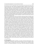
First it is necessary to be clear about the kind of joint to which the requirements
for full contact bearing should be applied. Figure 31.1(a) shows the normal case,
where the profile of a member is required to be in full contact bearing on a base-
plate or cap plate or division plate. The stress on the contact area equals the stress
in the member: thus full contact is needed to transmit this stress from the member
into the plate. Only that part of the plate in contact with the member need satisfy
the full contact bearing criteria, though it may be easier to prepare the whole plate.
Figure 31.1(b) shows two end plates in simple bearing.The potential contact area
is substantially larger than the cross-sectional area of the member: thus full contact
bearing is not necessary. All that is needed is for the end plates to be square to the
axis of the member.Another common case of simple bearing is shown in Fig. 31.1(c).
By contrast, the case shown in Fig. 31.1(d) is one where, if full contact bearing is
needed, it is also necessary to take special measures to ensure that the profiles of
the two members align accurately, otherwise the area in contact may be significantly
less than the area required to transmit the load. Particular tolerances should be
specified in such cases, based on the maximum local reduction of area that can be
924 Tolerances
Steel Designers' Manual - 6th Edition (2003)
This material is copyright - all rights reserved. Reproduced under licence from The Steel Construction Institute on 12/2/2007
To buy a hardcopy version of this document call 01344 872775 or go to
(a)
(b)
full contact
bearing
(location
material
not shown
for clarity)
(C)
(d)
accepted according to the design calculations. Alternatively a division plate could
be introduced; if the stresses are high this may well prove to be the most practical
solution.
31.4.3.2 Requirements
Where full contact bearing is required, there are in fact three different criteria
involved:
(1) Squareness.
(2) Flatness.
(3) Smoothness.
Fabrication tolerances 925
Fig. 31.1 Types of member-to-member bearing: (a) profile to plate, (b) plate to plate,
(c) flange to flange, (d) profile to profile (accurate alignment necessary)
Steel Designers' Manual - 6th Edition (2003)
This material is copyright - all rights reserved. Reproduced under licence from The Steel Construction Institute on 12/2/2007
To buy a hardcopy version of this document call 01344 872775 or go to
31.4.3.3 Squareness
If the ends of a length of column are not square to its axis, then after erection either
the column will not be vertical or else there may be tapered gaps at the joints,
depending on the extent to which surrounding parts of the structure prevent the
column from tilting. Under load any such gap will try to close, exerting extra forces
on the surrounding members. In addition, both a gap or a tilt will induce a local
eccentricity in the column.
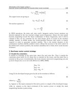
A practical erection criterion is that the column should not lean more than 1 in
x (where x is 600 in NSSS and 500 in ENV 1090-1). This slope is measured relative
to a line joining the centres of each end of the column length, referred to as the
overall centreline. The column is also allowed a lack of straightness tolerance of
(length/1000), which corresponds to end slopes of about 1/300 (see Fig. 31.2(a)). It
is thus necessary to specify end squareness criteria relative to the overall centreline,
rather than to the local centreline adjacent to the end (see Fig. 31.2(b)).
There is generally a design assumption that the line of action of the force in the
column does not change direction at a braced joint by more than 1/250, requiring
an end squareness in a simple bearing connection (relative to the overall axis of the
member) of 1/500 (see Fig 31.2(c)). However, full contact bearing generally arises
at column splices which are not at braced points, so an end squareness tolerance of
1/1000 is usually specified, producing a maximum change of slope of 1/500 (see Fig.
31.2(d)).
Once a column has been erected, it is more practical to measure the remaining
gaps in a joint. These gaps are affected not only by the squareness of the ends but
also by the second criterion, flatness.
31.4.3.4 Flatness
Ends have to be reasonably flat (as distinct from curved or grossly uneven) to enable
the load to be transferred properly. Following a history of arguments over appro-
priate specifications, the American Institute of Steel Construction (AISC) commis-
sioned some tests, which are the basis for their current specifications.
It was found that a surprisingly high tolerance was quite acceptable, and that
beyond its limit (or to compensate for end squareness deviations) the use of
localized packs or shims was acceptable. Basically similar rules are now beginning
to appear in other specifications including the CEN standard (see section 31.5.6 in
relation to erection tolerances). This is an essentially simple and effective method
of correcting excessive gaps on site (see also section 31.5.6). However, inserting
shims into column joints is not a matter to be undertaken lightly. It is normally more
economic to avoid the need for shimming by working to close fabrication tolerances
in joints where full contact bearing is required.
926 Tolerances
Steel Designers' Manual - 6th Edition (2003)
This material is copyright - all rights reserved. Reproduced under licence from The Steel Construction Institute on 12/2/2007
To buy a hardcopy version of this document call 01344 872775 or go to
slope = 1/250
parabolic curve
L/l000
end slope = 1/318.3
for sinusoidal curve
(a)
over—all
cent relin
1 in 500
4 1 in 500
over—all
centreline
in 250
(b)
(c)
(d)
—
squareness of end
(relative to over—all
centreline)
full contact
bearing
-ends square to over—all
axis within 1/1000
in 500 max
Fabrication tolerances 927
Fig. 31.2 Squareness of column ends. (a) Bow of 1/1000 giving end slopes of about 1/300.
(b) Squareness of end measured relative to overall centreline. (c) Change of direc-
tion at a braced joint. (d) End squareness at full contact bearing splice
Steel Designers' Manual - 6th Edition (2003)
This material is copyright - all rights reserved. Reproduced under licence from The Steel Construction Institute on 12/2/2007
To buy a hardcopy version of this document call 01344 872775 or go to
H-H
4
31.4.3.5 Smoothness
In the light of the findings of the flatness tests, it can be appreciated that if absolute
local flatness is not in fact needed, absolute smoothness is irrelevant also.
The best description of the smoothness that is needed is the smoothness of a
surface produced by a good-quality modern saw in proper working order. This
degree of smoothness is indeed very good.
Where sawing is not possible, ending machines (i.e. special end-milling machines)
can be used for correcting the squareness (or flatness) of ends of built-up (fabri-
cated) columns, such as box columns or other welded-up constructions.Where base-
plates are not flat and are too thick to be pressed flat, either they are milled locally
in the contact zone or else planing machines are used.
However, it cannot be overemphasized that the normal preparation for a rolled
section column required to transmit compression by full contact in bearing is by saw
cutting square to the axis of the member.
It is, of course, unnecessary to flatten the undersides of baseplates supported on
concrete foundations.
31.4.4 Other compression joints
Compression joints, transferring compression through end plates in simple bearing,
also need to have their ends square to the axis. If, after the members have been
firmly drawn together, a gap remains which would introduce eccentricity into the
joint, it should be skimmed.
31.4.5 Lap joints
Steel packs should be used where necessary to limit the maximum step between
adjacent surfaces in a lap joint (see Fig. 31.3) to 2 mm with ordinary bolts or 1mm
(before tightening the bolts) where preloaded HSFG bolts are used.
928 Tolerances
Fig. 31.3 Maximum step between adjacent surfaces
Steel Designers' Manual - 6th Edition (2003)
This material is copyright - all rights reserved. Reproduced under licence from The Steel Construction Institute on 12/2/2007
To buy a hardcopy version of this document call 01344 872775 or go to
31.4.6 Beam end plates
Where the length of a beam with end plates is too short to fit between the sup-
porting columns, or other supporting members, packs should be supplied to make
up the difference.
Gaps arising from distortion caused by welding, as shown in Fig. 31.4, need not
be packed if the members can be firmly drawn together. However, they may need
to be filled or sealed to avoid corrosion where the steelwork is external or is exposed
to an aggressive internal environment.
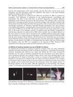
31.4.7 Values for fabrication tolerances
The values for fabrication tolerances currently given in the NSSS are reproduced
for convenience in Table 31.4. Each of the specified criteria should be considered
and satisfied separately. The cumulative effect of several permitted deviations
should not be considered as overriding the specific criteria.
These values represent current practice and are taken from the fourth edition of
the NSSS.
The clause numbers referred to in Table 31.4 are clause numbers in the NSSS,
which should be referred to for further information.
31.5 Erection tolerances
31.5.1 Importance of erection tolerances
Erection tolerances potentially have a significant effect on structural behaviour.
There are four matters to be considered:
(1) overall position,
(2) fixing bolts,
(3) internal accuracy,
(4) external envelope.
31.5.2 Erection – positional tolerance
31.5.2.1 Setting out
The position in plan, level and orientation can only be defined relative to some
fixed references, such as the National Grid and the Ordnance datum level. From the
Erection tolerances 929
Steel Designers' Manual - 6th Edition (2003)
This material is copyright - all rights reserved. Reproduced under licence from The Steel Construction Institute on 12/2/2007
To buy a hardcopy version of this document call 01344 872775 or go to
section B — B detail a A
r
VA
I
930 Tolerances
Fig. 31.4 End plate with welding (exaggerated)
Steel Designers' Manual - 6th Edition (2003)
This material is copyright - all rights reserved. Reproduced under licence from The Steel Construction Institute on 12/2/2007
To buy a hardcopy version of this document call 01344 872775 or go to
SECTION 7
WORKMANSHIP -
ACCURACYOF FABRICATION
7.1
PERMITTED DEVIATIONS
Permitted deviations in cross section, length, straightness, flatness, cutting, holing and
position of fittings shall be as specified in 7.2 to 7.5 below.
7.2
PERMITTED DEVIATIONS IN ROLLED COMPONENTS AFTER
FABRICATION
(Including Structural Hollow Sections)
7.2.1 Cross Section after Fabrication
In accordance with the
appropriate tolerances standard
given in Table 2.1
(Section 2)
A
7.2.2
Squareness of Ends Not
I
Prepared for Bearing
D
A =
D/300
See also 4.3.3 (i)
Plan or Elevation of End
7.2.3
Squareness of Ends Prepared
A
AD/l000
for
Bearing
Prepare ends with respect to the
900
- -
D.
longitudinal axis of the member.
See also 4.3.3 (ii) and (iii).
Plan or Elevation
L
7.2.4Straightness on Both Axes
A= L/l000 or 3mm
whichever is the greater
Erection tolerances 931
Table 31.4 (Extract from National Structural Steelwork Specification 4th edn.)
©BCSA
Steel Designers' Manual - 6th Edition (2003)
This material is copyright - all rights reserved. Reproduced under licence from The Steel Construction Institute on 12/2/2007
To buy a hardcopy version of this document call 01344 872775 or go to
7.2.5
Length
Length after cutting, measured un the
centre line of the section or on the
corner of angles.
7.2.6
Curved or Cambered
Deviation from intended curve or
camber at mid-length of curved
portion when measured with web
horizontal.
7.3
PERMITTED DEVIATIONS FOR ELEMENTS OF FABRICATED MEMBERS
7.3.1 Position of Fillings
Fittings and components whose
location is critical to the force path in
the structure, the deviation from the
intended position shall not exceed A.
7.3.2 Position of Holes
The deviation from the intended
position of an isolated hole, also a
group of holes, relative to each other
shall not exceed A.
7.3.3 Punched Holes
The distortion caused by a punched
___________________
holeshall not exceed A.
(see 4.6.4.)
7.3.4 Sheared or Cropped Edges of
Plates or Angles
The deviation from a 900
edge
shall
not exceed A.
A = 2mm
tion
L
Deviation =
L/l000or 6mm
whichever is greater
__________
A=3mm
A
= 2mm
PATh
A=D/loor
1mm
whichever is the greater
A
Th
F
N
A=
932 Tolerances
Table 31.4 (contd )
©BCSA
Steel Designers' Manual - 6th Edition (2003)
This material is copyright - all rights reserved. Reproduced under licence from The Steel Construction Institute on 12/2/2007
To buy a hardcopy version of this document call 01344 872775 or go to
7.3.5Flatness
Where frill contact bearing is specified,
A
A
the
flatness shall be such that when
measured against a straight edge not
exceeding one metre long, which is laid
against the full bearing surface in any
direction, the gap does not exceed A.
A=
0.75mm
7.4 PERMITTED DEVIATIONS IN PLATE GIRDER SECTIONS
7.4.1
Depth
Depth on centre line.
7.4.2
Flange Width
Width of B or B
7.4.3
Squareness of Section
Out of Squareness of Flanges.
7.4.4 Web Eccentricity
Intended position of web from
one edge of flange.
Erection tolerances 933
Table 31.4 (contd )
©BCSA
Steel Designers' Manual - 6th Edition (2003)
This material is copyright - all rights reserved. Reproduced under licence from The Steel Construction Institute on 12/2/2007
To buy a hardcopy version of this document call 01344 872775 or go to
B Flange width
7.4.5
Flanges
cja]—t.
A
Outof flatness.
A=
B/l00or 3mm
whichever is the greater
w =
Rail
width +
20mm
7.4.6
Top Flange of Crane Girder
w w
__
A
Outof flatness where the rail seats.
____________
7.4.7
Length
Length on centre line.
7.4.8
Flange Straightness
7A
Straightness
of individual flanges.
L
A=
L/1000or 3mm
whichever is the greater
7.4.9 Curved or Cambered
Deviation from intended curve or
camber at mid-length of curved _____________________
portion,
when measured with the
L
web horizontal.
Deviation =
L/i000or 6mm
whichever is greater
gauge length =
web
depth
7.4.10 Web Distortion
d[
Distortionon web depth or gauge
length.
A
d/150or 3mm
whichever is the greater
7.4.11 Cross Section at Bearings
Squareness of flanges to web.
934 Tolerances
Table 31.4 (contd )
©BCSA
Steel Designers' Manual - 6th Edition (2003)
This material is copyright - all rights reserved. Reproduced under licence from The Steel Construction Institute on 12/2/2007
To buy a hardcopy version of this document call 01344 872775 or go to
7.4.12 Web Stiffeners
Straightness of stiffener out of plane
with web after welding.
7.4.13 Web Stiffeners
Straightness of stiffener in plane with
web after welding.
7.5
PERMITTED DEVIATiONS IN BOX SECTIONS
7.5.1
Plate Widths
Width of B1 or B
7.5.2
Squareness
Squareness at diaphragm positions.
7.5.3Plate Distortion
Distortion on width or gauge length.
L
A
= d/500omm
whichever is greater
A = d/250or 3mm
whichever is greater
Bf
A
I
ii
B1
or B <300mm
A
= 3mm
B1 orB 300mm
A
= 5mm
A
A=D/300
IJfD
L
'Li
gauge
length =
width,
w
w[
A=w/lsoor3mm
whichever is the greater
Erection tolerances 935
Table 31.4 (contd )
©BCSA
Steel Designers' Manual - 6th Edition (2003)
This material is copyright - all rights reserved. Reproduced under licence from The Steel Construction Institute on 12/2/2007
To buy a hardcopy version of this document call 01344 872775 or go to
7.5.4
Web or Flange Straightness
Straightness of individual web or
flanges.
Straightness out of plane to plate
after welding.
Deviation from intended curve or
camber at mid-length of curved
portion when measured with the
uncambered side horizontal.
A= L/l000
or 3mm
whichever is the greater
L1\ = d/250or 3mm
whichever is greater
7.5.5 Web Stiffeners
Straightness in plane with plate
after welding.
7.5.6 Web Stiffeners
or 3mm
whichever is greater
7.5.7
Length
Length on centre line.
7.5.8 Curved or Cambered
IA=3mmp
ThIntion
Deviation =
LIl000 or6mm
whichever is greater
936 Tolerances
Table 31.4 (contd )
©BCSA
Steel Designers' Manual - 6th Edition (2003)
This material is copyright - all rights reserved. Reproduced under licence from The Steel Construction Institute on 12/2/2007
To buy a hardcopy version of this document call 01344 872775 or go to
national system, it is usual to set subsidiary site datum points, and often a site datum
level, and then refer the accuracy of the structure to these.
For any site the use of a grid of established column lines together with an
established site level is strongly recommended. For a large site it is virtually indis-
pensable. To help appreciate this, consider what happens on the site of a steel
structure.
31.5.2.2 Site practice
Normal site practice is for the supporting concrete foundations, and other support-
ing structures, to be prepared in advance of steel erection, generally by an organi-
zation separate from the steel erector. Depending on the system of holding-down
bolts or other fixings to be used, this may involve casting-in of holding-down bolts,
preparation of pockets in the concrete, and preparation of surfaces to receive fixings
to the steelwork.
Even with care, the standard of accuracy achievable is limited, and the concrete
requires time to harden to a sufficient strength for steel erection to proceed. Once
all the foundations etc. are available for steel erection (or at least a sufficient
proportion of them on a large site), it is prudent to survey them to review their
accuracy.
31.5.2.3 Established column lines and established site level
From this survey it is convenient to introduce a grid of established column lines
(ECL) and an established site level (ESL) of the foundations and other supporting
structures in such a way that the positions and levels of steel columns etc.can readily
be related to the site grid and site level.
The established column lines are defined as that grid of site grid lines that best
represents the actual mean positions of the installed foundations and fixings. Simi-
larly the established site level is defined as that level which best represents the actual
mean level of the installed foundations. Of course it should also be verified that the
deviation of the ECL grid and the ESL from those specified are within the relevant
permitted deviations.
31.5.3 Erection – fixing bolts
31.5.3.1 Types of fixing bolts
Fixing bolts include both holding-down bolts for columns and various types of fixing
bolts used to locate or to support other members, such as beams or brackets carried
by walls or concrete members.
Erection tolerances 937
Steel Designers' Manual - 6th Edition (2003)
This material is copyright - all rights reserved. Reproduced under licence from The Steel Construction Institute on 12/2/2007
To buy a hardcopy version of this document call 01344 872775 or go to
Holding-down bolts and other fixing bolts are either:
(1) fixed in position, or
(2) adjustable, in sleeves or pockets.
31.5.3.2 Fixed bolts
Fixed bolts used to be solidly cast in, an operation requiring care and the use of jigs
or templates to achieve accurately. However, they are now also commonly produced
by placing resin-grouted bolts in holes drilled in the concrete after casting. It may
also be possible to use expanding bolts.
In whatever way fixed bolts are achieved, they need to be positioned accurately,
as the only adjustment possible is in the steelwork, so relatively close tolerances are
normally specified.
31.5.3.3 Adjustable bolts
Adjustable bolts are placed in tubes or in tapered trapezoidal or conical holes cast
in the concrete, so that a degree of movement of the threaded end of the bolt is pos-
sible, while the other end is held in place by a steel washer or other anchoring device
embedded in the concrete.
This alternative permits the use of more easily achieved tolerances for the bolts,
while using relatively simple details for the steelwork.Adjustment of the bolt neces-
sitates its axis deviating from the vertical to some extent, and the holes in the steel-
work need to be large enough to allow for this, particularly if the baseplate is thick.
The use of loose plate washers is recommended to span oversize holes if necessary.
If required they can be welded in place after the bolts are tightened, but this should
not normally be necessary. ‘Particular’ tolerances need to be worked out for each
case, depending on the details, including the length of the bolts, because this affects
their slope.
31.5.3.4 Length of bolts
The level of the top of an HD bolt is also important to ensure that the nuts can be
fitted properly after erection. To provide the necessary tolerances for the fixing of
the bolts they should be longer than theoretically required, long threaded lengths
should be provided, and the nominal level for the top should be above the theoreti-
cal position.
Similar considerations apply to the lengths of fixing bolts located horizontally.
938 Tolerances
Steel Designers' Manual - 6th Edition (2003)
This material is copyright - all rights reserved. Reproduced under licence from The Steel Construction Institute on 12/2/2007
To buy a hardcopy version of this document call 01344 872775 or go to
31.5.4 Erection – internal accuracy
In terms of structural performance, the main erection tolerance is verticality of
columns; positions of beams etc. on brackets may also be important. Levels of
beams, particularly of one end relative to the other end and of one beam relative
to the next one, are important in terms of serviceability.
Otherwise the internal accuracy of one part of the structure relative to another
is largely a matter of assembly tolerances, provided that these do not cause any
problem of fit-up, interference or clearances. Where the structural accuracy result-
ing from the assembly tolerances is liable to infringe any of these limits, ‘particular’
tolerances should be specified.
The necessary tolerances are specified in relation to readily identifiable points
and levels. For columns and other vertical members, the reference points are con-
veniently defined as the actual centre of the member at each end of the fabricated
piece. For beams and other horizontal members the reference points are more con-
veniently defined by the actual centre of the top surface at each end. Either the
column system or the beam system should be used for any other cases, and the rel-
evant system should be indicated on the erection drawings. The tolerances are then
defined by the permitted deviations of these reference points from the established
column lines ECL and established floor level EFL.
The concept of an ECL grid and an established site level ESL have already been
explained in section 31.5.2.3.The established floor level EFL is defined as that level
which best represents the actual mean level of the as-built floor levels. The EFL
must not deviate from the specified floor level (relative to the ESL) by more than
the permitted deviation for height of columns.
The reference points for each beam must then be within the permitted deviation
from the EFL. In addition the difference in level of each end of a beam and the
difference in level between adjacent beams must also be within their respective
limits.
In the case of columns, the permitted deviations at each level form an ‘envelope’
within which the column must lie at all levels. In addition, the permitted inclination
of each column within a storey height is limited, but except where columns are fab-
ricated as individual storey-height pieces, the overall envelope normally governs.
31.5.5 Erection – external envelope
Generally the same erection tolerances for verticality apply to external columns as
to internal columns. When the envelope of extreme permitted deviations is plotted
from the extreme position of the base (allowing for the permitted deviation of the
ECL from the theoretical position as well as the permitted deviation of the column
base from the ECL), it may be found that this is unacceptable in terms of site bound-
aries or building lines, especially for a tall multi-storey building. If so, ‘particular’
tolerances should be specified.
Erection tolerances 939
Steel Designers' Manual - 6th Edition (2003)
This material is copyright - all rights reserved. Reproduced under licence from The Steel Construction Institute on 12/2/2007
To buy a hardcopy version of this document call 01344 872775 or go to