Installing, Troubleshooting, and Repairing Wireless Networks phần 6 pot
Bạn đang xem bản rút gọn của tài liệu. Xem và tải ngay bản đầy đủ của tài liệu tại đây (466.15 KB, 41 trang )
Figure 11.14
You can change the
wireless network
configuration by
selecting the
Networks menu
option.
Selecting the Profiles option from the Odyssey Client Manager lets
you choose from available profiles. Once one of the profiles is select-
ed, as in Figure 11.15, you can determine how it will be used to inter-
act with the Odyssey server.
Finally, you can add or review the servers your client trusts for
authentication and connection—it has certificates from—by selecting
Networks from the menu (see Figure 11.16).
When you first attempt a connection to your newly secured wire-
less network, you will see a password dialog pop-up. If you are using
Windows server log-on to complete the authentication process, use
your Windows network password. Your Windows log-on name is
already provided to the program from the username you logged onto
your PC from. You will not see the log-in prompt again until your
current authentication session has expired, requiring you to validate
your log-on again with your password. This is a typical and expected
feature—essentially logging you off the network connection if you
have been away from your computer for a length of time—to reduce
intrusions.
Chapter 11
190
Figure 11.15
The typical profile is
to use the Windows
server password for
authentication.
Figure 11.16
Networks your client
trusts for wireless
connections are
shown in the
Networks dialog.
Wireless Access and Security Solutions
191
WiMetrics: WiSentry Installation
WiSentry is a wireless network security monitoring tool that creates a
bridge between your intended wireless LAN setup and your wired
LAN. In addition to creating a bridge it provides a sentry or access con-
trol point on the wireless side of the bridge to either allow or deny spe-
cific wireless devices to gain access to the wired LAN on the other side.
It is suggested that you dedicate a Windows 2000 server to this
task rather than simply adding another network card to an existing
server because any unlikely security gap at the wireless side could
expose data on this server. Such a server should not be a Domain
Controller in an Active Directory infrastructure, nor should it have
any file or resource sharing enabled that might expose data files or
access control lists. Figure 11.17 shows the basic configuration for
this system integrated into your existing network.
Figure 11.17 How WiSentry integrates onto an existing wireless LAN.
You will need a few things to get started:
■
An adequate hardware platform to support Windows 2000 Server
software and multiple network cards, at a minimum:
– Typically a 333 MHz or better Pentium II, III or IV system
– 128–256 megabytes of RAM
– 4 to 6 gigabytes of hard drive space
Chapter 11
192
– Two 10/100 BaseT network cards installed
■
Windows 2000 Server, or Advanced Server software. Windows 2000
Professional and XP are also supported for WiSentry installations.
■
A DHCP server on the wired side of your network—this can be the
server on which you are installing WiSentry.
■
A wireless access point—Orinoco AP-2000 or equivalent commer-
cial unit is recommended.
■
Wireless client PC or laptop running Windows 98, Me, 2000, or XP,
and wireless adapter.
■
WiSentry software.
Windows 2000 Server Configuration
Start with a basic Windows 2000 Server configuration. Do to install
(or disable) Internet Information Server components and Routing
and Remote Access, unless you will integrate them into a WLAN por-
tal or provide an underlying login access control. If you do use Rout-
ing and Remote Access features, be aware that the server will then
contain user access information you probably do not want to expose
should the wireless connection be compromised. IIS is fraught with
security holes and is simply not an application or service I would
want exposed to unforeseen compromises.
As you install Windows 2000 Server, or after the installation is
complete, configure the network connections as follows:
■
Determine which LAN card will connect to the wired LAN and
which will be used for the wireless access points.
■
Provide fixed IP addresses within your wired LAN subnet to each
of the LAN cards.
■
You may wish to configure a specific subnet for wireless services,
and configure this into your internal router as well.
■
Set the Gateway addresses for each card to the address of your
internal router.
■
Configure DNS addresses.
■
Configure WINS server address as appropriate.
■
Configure this server to provide DHCP addresses for the wired
LAN subnet. This is optional if you already have a DHCP server
on the wired network.
Wireless Access and Security Solutions
193
With this basic configuration in place, connect your wireless
access point to the LAN card assigned to this purpose, and the wired
LAN to the respective LAN card for it. Next, configure your access
point, providing the following:
■
A fixed IP address
■
Gateway address for the wired LAN
■
SSID for the access point
■
If available, do not enable DHCP from the access point; DHCP will
pass through to the server or wired LAN
■
Type of security you wish to use—conventional security methods
are supported once wireless clients or additional access points are
authorized access through the bridge
■
WEP keys, if appropriate
WiSentry Installation and Use
The WiSentry installation is straightforward, beginning with a nor-
mal Windows installation process, followed by installation of Sun’s
Java Runtime Environment. A reboot of the server is required to
complete the installation and activate the bridge service. Once the
server reboot is complete, the installation finishes, and you are ready
to run the WiSentry administrative program which serves as the
access control point and alerting mechanism for wireless clients.
When run, the WiSentry administrative program (shown in Figure
11.18) begins to sniff the networks for access points. Discovered
access points appear on a listing of Active devices. Viewing this list
shows you all known wireless devices and what type of device they
are, along with the device’s MAC address and any IP addresses
assigned to them. Color coding indicates if they are unauthorized or
authorized. Initially all found devices except the bridge service is
color-coded red to indicate it is unauthorized.
Your first action will be to identify which device is your access
point, then authorize it so it can be used to pass wireless clients to
the wired LAN. This is done by selecting Authorize from the Action
item on the top menu bar of the program. Once the access point is
authorized you can evaluate all wireless client devices and choose
whether or not to authorize them for LAN access.
Chapter 11
194
Wireless client devices will be able to associate with an access
point but will not be able to obtain an IP address from or access the
wired LAN until they are authorized. This enforces that you must
know which wireless devices exist and be able to identify them by
MAC address or host name before authorizing them for LAN access.
You can leave WiSentry running smoothly by itself, checking
every so often for rogue access points and new wireless clients wan-
dering around in range of the WLAN, but you will probably want to
set some alarms to pop-up and alert you to any new activity. Figure
11.19 show the alert configuration screen, with the types of possi-
ble intrusions that can be detected and how you want to be notified
of them.
You can configure the alarms and monitor the system on a sepa-
rate workstation rather than just the server. As shown in Figure
11.20, when an intruder, an unauthorized access point, or wandering
client try to communicate with your network, you will get a pop-up
dialog and a list of devices and their classification.
Wireless Access and Security Solutions
195
Figure 11.18 The WiSentry administrative program is where active wireless devices are detected, reported,
and authorized, or denied access to the wired LAN.
Figure 11.19
Alert configuration in
WiSentry provides
options for the type
of possible intrusion
you wish to be
notified of and how.
Figure 11.20
The WiSentry alert
pop-up tells you
what type of device
is connecting to your
WLAN or if rogue
access points have
been connected.
Chapter 11
196
Once you receive an alert you will want to review the Unautho-
rized Devices portion of the administrative screen to get more infor-
mation about the identity of the intruding device (Figure 11.21) and
then authorize it if appropriate.
Figure 11.21 WiSentry provides the name, MAC address, and IP address of unauthorized devices so you
identify them and determine if you wish to allow them access to your network resources.
As you can see, WiSentry packs a lot of work behind the scenes
and makes it easy to deal with WLAN security and access issues.
ISS: Wireless Scanner
While you can control access to and through your WLAN, and you can
see which devices are trying to connect to it, it’s still a good idea to
have an idea of how your WLAN security configuration appears from
the inside out. Internet Security Systems has produced a wireless ver-
sion of their network security scanning software. First, ISS is intended
Wireless Access and Security Solutions
197
to be installed on a system with a PC Card WLAN adapter—so a lap-
top or desktop with PC Card adapter is required. Using a laptop
allows you to roam about and get close to access points and sniff out
unknown or rogue APs. Once installed you should run its driver con-
figuration program to get a driver in place that will allow the scanning
software to properly control the WLAN card and take in everything in
the air. This driver will likely render the card unable to connect with
your present network, and the driver configuration program allows
you to switch back to the LAN-functional driver as needed.
Once the sniffing driver is ready to go you can begin taking live
scans of the airwaves around you. Data is collected and presented on
three different views—the first (Figure 11.22) is of detected access
points, the second (Figure 11.23) is of detected vulnerabilities, and
the third (Figure 11.24) is of detected wireless clients. The MAC or
hardware address for each device makes it somewhat easier to iden-
tify the device.
Figure 11.22 The ISS Wireless Scanner summary listing of discovered access points shows MAC address,
channel used, signal strength, and time detected.
Chapter 11
198
Figure 11.23 The Vulnerabilities view in Wireless Scanner gives a summary listing of potential issues and
their severity.
These views are simply summary listings of what has been detect-
ed. Once you have collected a data sampling, go to the Reports menu
selection and create one of several available reports to understand
the WLAN environment, have an inventory of the devices, and an
assessment of any vulnerability issues. A sample report of technical
details is shown in Figure 11.25.
The Technical Details reports breaks down everything known
about detected devices and the vulnerabilities found in them. This
report will give you the call-to-action to begin securing your network.
The two most common issues you will find in most WLAN setups are
either the lack of encryption requirement at an access point and
broadcasting the SSID, which can identify the owner or location of a
particular access point.
Wireless Access and Security Solutions
199
Figure 11.24 The Wireless Clients view shows client adapters that have been detected, their MAC address,
and manufacturer.
Summary
There are many ways to approach wireless LAN access, security, and
intrusion issues. A product like Odyssey deals with authenticating (or
not), specific clients—a front-end positive approach to authorizing
access to a network. Odyssey provides end-to-end encryption, but it has
no awareness of possible intrusions. WiSentry provides both front- and
back-end approaches to access control, and although it is not a specific
authentication or encryption solution, it will work with the methods
you choose for this purpose. ISS’s Wireless Scanner adds another level
of detail to knowing what is going on in your wireless LAN environ-
ment and will help you tighten up any obvious security gaps.
Chapter 11
200
Figure 11.25 The ISS Wireless Scanner detailed report shows the specific problems and solutions for clients
and access points with vulnerabilities.
Odyssey and WiSentry are not unlike similar add-on programs
that build upon an existing infrastructure and user base to quite
simply provide security in the form of access control. Similar fea-
tures could be implemented using Windows IPSec at the client and
server, but managing the process is not as easy, and network options
are not as flexible for the client side. Similarly, security alerts about
possible intrusions and rogue access points like the ones WiSentry
provides, or the vulnerability reports of Wireless Scanner, could be
obtained from sniffer products like AirMagnet, but AirMagnet and
Wireless Scanner do nothing to stop the intrusions.
Wireless Access and Security Solutions
201
Perhaps knowing about these methods and how vulnerabilities
can be revealed will get you to tighten up your network as you build
it. You might think you can avoid using some of these tools, but as
your WLAN grows so will the responsibilities and time to manage all
of the components—requiring you to consider something to help give
you peace of mind.
Chapter 11
202
System
Configuration
Data
CHAPTER
12
Copyright 2003 by The McGraw-Hill Companies, Inc. Click Here for Terms of Use.
It seems that every time my friends or co-workers set out to add
something new to their personal computer (PC), they run into a con-
flict with one device or another, or have some piece of misbehaving
software that prevents them from doing what they wanted to do or
from using their new toy.
My intent with this chapter is to condense years of support work
into a quick reference you can use to get yourself out of trouble if you
are adding a network card or other adapter to your system, when
creating a new wireless or shared network system. This information
is not limited or specific to wireless networking. It is also useful for
adding any type of peripheral to your system—which you are likely
to do when your experience expands and you try to grow your com-
puting interest beyond one simple PC.
Legacy Devices
Legacy devices, if not preset or fixed in their configuration when built
into the motherboard or system board, require us to manually set
jumpers (tiny connections between two protruding connector pins) or
switches on system boards or I/O cards, usually in accordance with a
table of possibly dozens of variations of settings, and in comparison to
or in contrast with other devices in our PCs. Legacy devices typically
do not lend themselves to automatic or software-driven reconfigura-
tion, as may be possible with today’s plug-and-play devices.
Several legacy devices that we have no configuration control over
are:
■
Central processing unit (CPU) and numeric processor using fixed
addressing and interrupt request (IRQ) 13
■
Clock and timer resources using fixed addresses and IRQs 0 and 8
■
Memory and device addressing chips using DMA channels 0 and 2
■
Keyboard using fixed addressing and IRQ 1
■
Diskette drives using known/expected addressing and IRQ 6
■
Video display adapter using known/expected addressing
These listed devices are part of the system board or basic
input/output system (BIOS) programming and, as with other devices
we will see, must remain as-is for a PC to function as a PC.
Chapter 12
204
Almost all PC devices prior to implementation of the plug-and-
play standard are considered legacy devices. These include add-in
cards and other accessories, and to some extent, the basic PC system
itself. In most cases, legacy devices present the bulk of the configura-
tion and conflict issues we face in dealing with PCs. The next section
addresses the most common types of add-in devices with which you
could encounter configuration problems.
Logical Devices
Logical devices are those that have obscure abbreviated names asso-
ciated with a function or a particular device. They are associated to a
specific I/O address by program logic that assigns logical names to
devices in the order they are found. This is true even for plug-and-
play/universal serial bus (USB) devices—although the rules and
results of plug-and-play and auto-configuration seem quite out of
order, random, and illogical in some cases.
IBM originally provided for a handful of devices its developers
believed we might use. These include:
■
COM (serial) and LPT (parallel) I/O ports (which are probably the
ones we are most often concerned with)
■
Disk drives (A:, B:, C:, etc.)
■
Keyboard and video output (combined as the CON: or system con-
sole)
This is a good list for the most part. Unfortunately, this list of com-
mon logical devices has not been expanded, except to add LPT2:,
LPT3:, COM3:, COM4:, and the occasional special hardware and soft-
ware interfaces that give us other unique COM and LPT devices.
In actual use with programs and DOS, these devices must be
expressed with their numerical designation followed by a colon
(LPT1:, for example, and COM2:), while generically, it is LPT and
COM. Specifying only LPT or COM in DOS commands will result in
an error message, and the desired command or operation will not
occur. For the console and devices of which there is only one of that
type, there is no number. You may see CON, but the computer must
use CON:.
System Configuration Data
205
The logical assignment of parallel I/O (LPT) ports to specific hard-
ware addresses is not as critical for most applications as is the
assignment of serial I/O (COM) ports. Most software that uses the
COM ports work directly with the hardware, bypassing the features
built into the system BIOS (because doing so is much faster than
using the BIOS features). Because most communications applica-
tions access the hardware directly, but make their own assumptions
about logical names and physical addresses, the physical and logical
device matching, in the order shown in Table 12.1, is expected and
critical. Communications applications also require specific, matching
IRQ assignments to function properly.
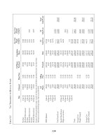
Consider Table 12.1, a listing of the most common physical and
logical devices encountered in a PC system, to be a foundation set of
rules for your system configuration.
TABLE 12.1
Logical versus
specific physical
translations for
common PC
devices
The issue of logical versus physical devices in a PC is not always
an easy one to understand, much less explain. Yet this issue is one of
the most significant rule-creating and binding aspects of a PC sys-
tem, and the root of many conflicts. The easiest way to deal with this
issue is to simply follow the original rules that IBM defined for all of
Chapter 12
206
Logical Physical
Address Address IRQ Device Name
COM 1 3F8-3FFh IRQ 4 1st Serial I/O Port
COM 2 2F8-2FFh IRQ 3 2nd Serial I/O Port
COM 3 3E8-3EFh IRQ 4 3rd Serial I/O Port
COM 4 2E8-2EFh IRQ 3 4th Serial I/O Port
LPT 1 3BC-3BFh IRQ 7 1st Parallel I/O Port (on monochrome systems)
LPT 1 378-37Fh IRQ 7 1st Parallel I/O Port (on color systems)
LPT 2 378-37Fh IRQ 5 2nd Parallel I/O Port if LPT1: is at 3BCh
LPT 2 278-27Fh IRQ 5 The accepted LPT2 device on color systems
LPT 3 278-27Fh IRQ 5 3rd Parallel I/O Port
(Note: h indicates a hexadecimal number.)
the devices in your system. In fact, that is what is advocated
throughout this book—knowing the configuration rules and comply-
ing with them.
Logical assignments occur during the Power-On Self-Test (POST)
that runs when you boot up your system. The system BIOS performs a
series of equipment checks, looking for specific devices at specific phys-
ical addresses in a specific order. As these devices are found, they are
assigned sequential, logical port numbers. BIOS uses this information
to refer to the I/O ports for any application that happens to rely on the
system BIOS to provide access to these ports. Thus, when you are
working directly with DOS or its applications, such as PRINT, and you
send a file to be printed to LPT1:, DOS passes some control over the
printing to the system BIOS, and the BIOS sends the file to the physi-
cal device associated with the “name” of LPT1:. The process works
similarly in Windows 3.1-Me and changes dramatically with Windows
NT, 2000, and XP, avoiding BIOS assignments altogether and replac-
ing them with similar functions within the operating system.
Where problems originate is in the fact that POST bases its nam-
ing strictly on a first-come, first-served basis. Although the logical
and physical addresses are designed to be matched as shown in the
table, and those addresses are what your system and devices will be
looking for during operation, the actual order in which these logical
devices are assigned may differ.
The apparent confusion and variable assignments for LPT ports
(as noted in Table 12.1) begins with IBM providing a parallel port at
3BCh using IRQ7 on monochrome display video adapters. Any paral-
lel port added to a system had to be at either 378h or 278h. When
IBM introduced color systems (CGA, EGA, and PGA), it did not pro-
vide a parallel port on the card. Any parallel port provided with or
added to these systems was configured for address 378h. Quite possi-
bly, this is because you could have both a monochrome display
adapter and a color display adapter in the same system, working at
the same time. Subsequently, for a color system with an add-in par-
allel port at 378h, a second port was provided for at 278h.
Always keep in mind that the numeric designation indicates a
logical ordering of devices. A good way to remember this is that, in
order to have a No. 2 or a second of something, you must have a No.
1 or a first of something. You simply cannot reserve, save, or leave
gaps in the logical numbering of the devices, as some people have
wanted to do.
System Configuration Data
207
Changing Your Configuration
We usually cannot, and probably would not want to alter the
extremely low-level internal configurations of our PC system boards
(direct memory access [DMA] channels, clock interrupts, etc.). How-
ever there are numerous devices we can, and often must, deal with
the configuration of throughout the life of any PC system.
Among the frequently added, changed, or removed devices antici-
pated in the original IBM PC, and subsequently the PC/AT, we typi-
cally encounter configuration issues with:
■
Serial I/O ports, including internal modems (COM)
■
Parallel I/O ports (LPT)
■
Video display adapters (MDA, CGA, EGA, PGA, VGA)
■
Disk drive interfaces (AT, IDE, SCSI)
■
Network interface cards
Developments after the first PC and AT systems provided us with
a few new device types to find resources for:
■
Pointing device interfaces—bus mouse and PS/2
■
Small computer system interface (SCSI) host adapters
■
Multimedia/sound cards, with and without CD-ROM interfaces
■
Video capture boards
■
3-D video accelerators
■
Custom document scanner interfaces
■
Internal integrated services digital network (SDN) adapters
■
Add-in or built-in infrared I/O ports
All of the devices in our systems require system resources. We can
usually take for granted that each device consumes power, creates
heat, and must be cooled by one or two meager fans. In addition, all
devices in our PC system consume computer-specific resources other
than power and space.
Of the devices we can have active simultaneously, not counting the
internal system board resources, these are typically:
■
Mouse (IRQ 12)
■
COM1 (IRQ 4)
Chapter 12
208
■
COM2 (IRQ 3)
■
LPT1, 2, and/or 3 (usually not using IRQ 5 or 7)
■
Hard drives (IRQ 14, 15)
■
Diskette drive (IRQ 6, DMA 2)
■
Sound card (IRQ 5 and/or 7, and DMA 1, 3, or 5)
■
CD-ROM (w/ disk drives, sound, or SCSI—IRQ 11, DMA 1, or 3)
■
Network interface (likely IRQ 5, 7, or 10)
This list makes a fairly full and typical system nowadays, though I
know folks who try to add scanner interfaces, infrared I/O ports,
extra COM ports, etc., and simply fail to realize that something must
be sacrificed to gain any satisfaction with any one or more of these.
The installation of any new device, or any changes to a device,
must be done with the limited availability of these resources in
mind, and a knowledge (through the inventory described in Chapter
1) of which resources are being used by other devices.
I/O Addresses
Every hardware device plugged into the I/O slot connectors inside
our PCs requires a unique hardware address. During program execu-
tion, data and commands are written to or read from these locations.
IBM originally defined that specific devices occupy very specific
addresses. Some of these devices are internal to the system board or
specific to IBM products and uses. Among these, some addresses are
reserved, or are to be avoided, because of other system- or IBM-spe-
cific uses, leaving approximately 25 possible addresses for all the
possible devices, features, and options we may want to put into our
PCs. This is a situation where some devices require 4, 8, or even 32
locations each.
The addresses that are defined, but not specifically reserved, are
used for the common I/O devices that IBM planned for and anticipat-
ed in its original system developments. These are the devices we are
most familiar with—COM ports, disk drives, and so on. In the pro-
gression from the original PC to the PC AT, a few new devices were
added, or the primary address of a major functional device (the hard
drive adapter, for example) was changed to accommodate the growth
from 8-bit to 16-bit systems and more options.
System Configuration Data
209
Tables 12.2 and 12.3 list the specific I/O addressing for PC-, PC/XT-,
and PC/AT-class systems. Many of the technical terms in the tables
are beyond our need to define and understand in the context of con-
figuration management, but we do need to know that something is
assigned at a given address. This list is compiled from the dozens of
I/O devices, specifications, and commonly available PC reference
material.
TABLE 12.2
The Original IBM
PC and PC/XT
Device Addresses
Chapter 12
210
I/O Address System Use or Device
000-01Fh DMA Controller—Channels 0–3
020h, 021h Interrupt Controllers
040-043h System Timers
060h Keyboard, Aux.
070h, 071h Real Time Clock/CMOS, NMI Mask
081-083h and 087h DMA Page Register (0–3)
0F0-0FFh Math Coprocessor
108-12Fh Not Assigned; Reserved by/for IBM Use
130-13Fh Not Assigned
140-14Fh Not Assigned
150-1Efh Not Assigned; Reserved by/for IBM Use
200-207h Game Port
208-20Bh Not Assigned
20C-20Dh Reserved
20E-21Eh Not Assigned
21Fh Reserved
220-22xh Not Assigned
230-23xh Not Assigned
240-247h Not Assigned
250-277h Not Assigned
278-27Fh LPT 2 or LPT 3—3rd Parallel I/O Port
(continued on next page)
TABLE 12.2
The Original IBM
PC and PC/XT
Device Addresses
(continued)
System Configuration Data
211
I/O Address System Use or Device
280-2Afh Not Assigned
2B0-2DFh Alternative EGA Port
2E1h GPIB 0
2E2h, 2E3h Data Acq 0
2E4-2E7h Not Assigned
2E8-2Efh COM 4—4th Serial I/O Port
2F8-2FFh COM 2—2nd Serial I/O Port
300-31Fh IBM Prototype Card
320-323h Primary PC/XT Hard Disk Adapter
324-327h Secondary PC/XT Hard Disk Adapter
328-32Fh Not Assigned
330-33Fh Not Assigned
340-34Fh Not Assigned
350-35Fh Not Assigned
360-363h PC Network Card—Low I/O Port
364-367h Reserved
368-36Ah PC Network Card—High I/O Port
36C-36Fh Reserved
370-377h Secondary Diskette Drive Adapter
378-37Fh LPT 2 or LPT 1—1st or 2nd Parallel I/O Port
380-389h Not Assigned
380-38Ch BISYNC_1 or SDLC_2
390-393h Cluster Adapter
394-3A9h Not Assigned
3A0-3ACh BISYNC_2 or SDLC_1
3B0-3BFh Monochrome Video Adapter
3BC-3BFh 1st Parallel I/O Port—Part of Monochrome Video Card
(continued on next page)
TABLE 12.2
The Original IBM
PC and PC/XT
Device Addresses
(continued)
TABLE 12.3
The Original IBM
PC/AT Device
Addresses
Chapter 12
212
I/O Address System Use or Device
3C0-3CFh EGA Video
3D0-3DFh CGA Video
3E0-3E7h Not Assigned
3E8-3EFh COM3—3rd Serial I/O Port
3F0-3F7h Primary Diskette Drive Adapter
3F8-3FFh COM 1—1st Serial I/O Port
I/O Address System Use or Device
000-01Fh DMA Controller—Channels 0–3
020h, 021h Interrupt Controllers
040-043h System Timers
060h Keyboard, Aux.
070h, 071h Real Time Clock/CMOS, NMI Mask
081h, 082h, 083h, and 087h DMA Page Register (0–3)
089h, 08Ah, 08Bh, and 08Fh DMA Page Register (4–7)
0A0-0A1h Interrupt Controller 2
0C0-0DEh DMA Controller Chs. 4–7
0F0-0FFh Math Coprocessor
108-12Fh Not Assigned or Reserved
130-13Fh Not Assigned
I/O Address System Use or Device
140-14Fh Not Assigned
150-1EFh Not Assigned or Reserved
170-177h Secondary PC/AT+ Hard Disk Adapter
1F0-1F7h Primary PC/AT+ Hard Disk Adapter
200-207h Game Port
(continued on next page)
TABLE 12.3
The Original IBM
PC/AT Device
Addresses
(continued)
System Configuration Data
213
I/O Address System Use or Device
208-20Bh Not Assigned
20C-20Dh Reserved
20E-21Eh Not Assigned
21Fh Reserved
220-2FFh Not Assigned
230-23Fh Not Assigned
240-247h Not Assigned
250-277h Not Assigned
278-27Fh LPT 2 or LPT 3 —3rd Parallel I/O Port
280-2AFh Not Assigned
2B0-2DFh Alt. EGA
2E1h GPIB 0
2E2h & 2E3h Data Acq 0
2E4-2E7h Not Assigned
2E8-2EFh COM 4—4th Serial I/O Port
2F8-2FFh COM 2—2nd Serial I/O Port
300-31Fh IBM Prototype Card
320-323h Not Assigned
324-327h Not Assigned
328-32Fh Not Assigned
330-33Fh Not Assigned
340-34Fh Not Assigned
350-35Fh Not Assigned
360-363h PC Network Card—Low I/O Port
364-367h Reserved
368-36Ah PC Network Card—High I/O Port
36C-36Fh Reserved
(continued on next page)
TABLE 12.3
The Original IBM
PC/AT Device
Addresses
(continued)
The addresses that were not planned for or assigned by IBM make
up the only address locations that are available to be exploited by
new devices. IBM did not and could not anticipate the existence of
these devices before they existed. New devices not defined by IBM
had to squeeze into the few address spaces left. The addresses shown
in Table 12.4 are typical of non-IBM add-on devices.
TABLE 12.4
Common
Aftermarket or
Non-IBM Devices
Listed by
Addresses Used
Chapter 12
214
I/O Address System Use or Device
370-377h Secondary Diskette Drive Adapter
378-37Fh LPT 2 or LPT 1—1st or 2nd Parallel I/O Port
380-389h Not Assigned
380-38Ch BISYNC_1 or SDLC_2
390-393h Cluster Adapter
394-3A9h Not Assigned
3A0-3ACh BISYNC_2 or SDLC_1
3B0-3BFh Monochrome Video Adapter
3BC-3BFh 1st Parallel I/O Port—Part of Monochrome Video Card
3C0-3CFh EGA Video
3D0-3DFh CGA Video
3E0-3E7h Not Assigned
3E8-3EFh COM3—3rd Serial I/O Port
3F0-3F7h Primary Diskette Drive Adapter
3F8-3FFh COM 1—1st Serial I/O Port
I/O Address System Use or Device
130-14F SCSI Host Adapter
140-15F SCSI Host Adapter (as may be found on a sound card)
(continued on next page)