Installing, Troubleshooting, and Repairing Wireless Networks phần 8 potx
Bạn đang xem bản rút gọn của tài liệu. Xem và tải ngay bản đầy đủ của tài liệu tại đây (449.56 KB, 41 trang )
antennas and, to some extent, larger equipment. Higher frequencies
dictate smaller antennas and equipment, but need more power
(which also means more equipment) to go the same distance. Still
another is that the distance covered by radio communications varies
with the frequency and with the weather—at least the weather at
very high altitudes, in the ionosphere—something for which we have
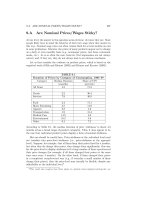
no known control. These factors and the general behavior of radio
signals at different frequencies are fairly well known and tend to dic-
tate classes of service or application-specific uses for the different
frequencies.
We use some of these limitations to our advantage when figuring
out what part of the radio spectrum is best for what we intend to
communicate over it, and where we want it to go. For this reason, for
example, cellular telephones that have to communicate only a mile
or two to a nearby base station can use low power at very high fre-
quencies. And those frequencies can be reused over and over again in
other cells nearby. You would not use a huge radio with a 200-foot
long antenna for something like cellular telephones, as the idea of
portable brings up visions of trucks and trailers full of equipment.
We know a cellular telephone-type radio cannot broadcast very far,
but a larger radio and antenna at a lower frequency can, so we use
those parts of the radio spectrum for long-distance communication
around the Earth.
What we find is that some of the radio spectrum is reusable or can
be used simultaneously by separating its reuse to areas beyond the
range it normally covers, and we have been doing that for years. For
instance, 1070 KHz AM broadcast radio stations exist in only three to
four different parts of the United States, while perhaps 20 or 30 101.3
MHz FM broadcast stations exist in the same larger geographical
area. And there are more in other countries, just as there are multiple
Channel 3 or Channel 21 television stations around the world.
Because we know how most radio waves and the ionosphere
behave, and we have learned how to design antennas to shape the
pattern the radio signals emit, we can tailor the amount and direc-
tion of signal. An FM radio signal, for instance, does not need to
broadcast to the stars, so the antenna pattern is tailored to place
that signal down into the local listening area and not much beyond
the primary area of interest. Doing this, we can cellularize radio fre-
quency reuse around the country and around the world. One of the
enemies of reuse is boosting the power to get a signal just a little bit
Chapter 15
272
farther out there. And in doing so, we may infringe on someone else’s
territory, causing interference. The frequency, direction (or focus),
and the power of various radio signals is, thus, regulated to avoid
interference between users. This is a very important consideration
when dealing with a limited resource, and a resource that has limita-
tions on how much of it we can practically use.
Cellular phone service has or had only 40 to 50 800 to 900 MHz-
range channels to share, and there are thousands of phone cells
throughout the country. We also anticipate there are, or will be, mil-
lions of wireless networking devices using 2.4 or 5 GHz spectrum all
over the world—and perhaps several hundred of them within 1 to 5
miles of yours. Above 2 to 5 GHz, it becomes impractical to use radio
spectrum for anything but point-to-point communications—satel-
lites, microwave hops from place to place, etc. We do not want to use
10 GHz radios for personal communications devices because water
resonates near that frequency and a high percentage of human mass
is water…make a phone call, boil your brain….
So, we have learned since the days of Marconi how different parts
of the radio spectrum behave, how the atmosphere behaves, how to
control the power levels, and how to tailor antennas to focus and
optimize signals to specific areas, with the result that we can reuse
the same frequencies many times in different areas of the world.
What we have not been able to do is make more radio units avail-
able; thus we have to work out better sharing arrangements or
repurpose some of the spectrum we have been using if we want to do
more or different things.
As good (as in beneficial to us and financially successful to the
manufacturers) as the implementation of 802.11a and 802.11b have
been so far in the limited amount of spectrum allotted to them, there
is speculation and investigation into broadening the use of radio for
data networks, and, of course, which part of the greater radio spec-
trum can be used for it. While computer networking looks to expand,
so do police and fire and other types of communications, causing a
major reshuffling of television channels and a push to digital TV
broadcasts that can use more of the original television space for more
and different radio uses. The U.S. Federal Communications Commis-
sion (FCC) has begun a new Spectrum Policy Task Force
( to study the current and future demands of
radio spectrum use, leading to possible changes in who uses what
parts of the spectrum and how.
Upcoming Standards and Trends
273
Data networking over wireless is in competition with cellular
phones, your local police department, domestic and international
broadcast stations, other governments, and probably dozens of other
nonobvious uses—weather tracking, military purposes, etc. It is an
ongoing struggle to obtain and use more and more of what there is
no more of—practical, usable radio spectrum. Like land, they just
are not making any more these days. Obviously, a lot of uses and
reuses and reallocations have to be thought up, fought over, negotiat-
ed, and perhaps even bought and sold somehow (the U.S. govern-
ment’s latest way to make money).
If you are into lobbying or just enjoy the intrigue of geopolitical
and economic issues, keep an eye on what the FCC and similar gov-
ernment agencies around the world are thinking about doing with
radio spectrum. While you are monitoring the action there, keep in
mind the points made throughout this book about certification of
wireless devices and complying with radio regulations. Become
familiar with the rules and regulations presented in Chapter 1. If we
think we deserve more radio spectrum for wireless networking, the
chances of getting it will be in our favor if we can and will stay with-
in the laws that govern what we do now.
Going Beyond Current Wireless
Networking Standards
IEEE 802.11b and then 802.11a differed in both RF spectrum and
modulation technologies, but share wired equivalent privacy (WEP)
encryption and support for other security or privacy methods. Pend-
ing IEEE standard 802.11g brings some of 11a’s technology to 2.4
GHz devices for higher throughput. Pending IEEE standard 802.11i
will bring a greater level of security to all three technologies—11a,
11b, and 11g.
Typically, for business reasons—that is, the vendors, dealers, and
retailers need to make money—many manufacturers are not waiting for
the standards committees to release the standards before making and
selling new devices with the capabilities they expect to be approved.
Could there be problems for users of equipment with the new tech-
nologies before the standards are final? Yes!
Chapter 15
274
Fortunately, the problems of prestandards wireless technology may
not be as significant as the differences and incompatibilities between
the separate, competing v.90 and X2 modem technologies of a few
years ago, when Internet service providers (ISPs) and users had to
pick and choose which one they were going to support, if not both.
At best, we can hope that there will be no technology changes
between prestandards-release products and poststandards-release
products. Vendors feel that the pending issues are informalities, not
technologies. The worst case is that you end up buying a set of pre-
standards gear that will only work with itself and current equip-
ment, but not with poststandards-release equipment, which is fine if
you are not building or expanding a huge network with a lot of users.
Between best- and worst-case scenarios may be that equipment
vendors release new firmware for you to upload into your equipment
to bring it up to date. This is not an unusual circumstance, as the
release of nearly every piece of computer equipment sold is followed
by at least two to three updates of firmware or driver software to fix
a bug or add an incremental feature. Certainly corporations looking
to invest in several pieces of wireless equipment may wish to wait
until some technologies have stabilized before purchasing and
deploying, to avoid the expense and hassle of updating dozens of
access points and client adapters.
802.11g—Higher Speed at 2.4 GHz
The IEEE 802.11g standard will not be released until the spring or
summer of 2003 at the earliest. When adopted and released, it will
provide for new interradio operating modes and bit-rate (transfer
speed) throughput improvements, while integrating four different
wireless standards. Though the standard is not yet released, many
chip manufacturers feel that the technical issues are solid enough to
have made and sold new chips implementing the technologies, and
WLAN equipment makers are already making enhanced client and
access point products with those chips.
You will see these devices advertising 22 Mbps and possibly 54
Mbps, but none can legitimately claim compatibility with 802.11g
until the standard is approved. These throughput levels would be
meaningless and a waste unless the wired network behind them is
Upcoming Standards and Trends
275
100BaseT or Gigabit Ethernet, so now wireless portable computers
can begin to feel more like their hard-wired counterparts on current
local area networks (LANs).
802.11g will remain compatible with 802.11b by keeping function-
al support for 802.11b’s complementary code keying (CCK) for bit
transfer rates of 5.5 and 11 Mbps. 802.11g adds orthogonal frequency
division multiplexing (OFDM), as used in 802.11a devices, to deliver
54 Mbps speeds in the 2.4 GHz range.
802.11g also comes with two new modes that can provide through-
put up to 22 Mbps. Intersil’s 802.11g chipset will use a combined
CCK-OFDM mode for throughput of 33 Mbps. Texas Instrument’s
chipset uses a packet binary convolutional coding (PBCC-22) mode
for a variable throughput from 6 to 54 Mbps. Other chip vendors
may have one or the other or both technologies in them.
While 802.11g is not expected to provide any improvements to
range of coverage, testing has shown it to maintain connectivity at
the same range or slightly better range than 802.11b; however,
802.11b may still transfer data faster than 802.11g at the far end of
the signal range.
For those of us with smaller wireless local area networks
(WLANs), say 10 or fewer users in a modest office space, 802.11g’s
higher throughput will probably be very beneficial. If your WLAN
initiative needs to support a lot of users, it is important to consider
that 802.11b and g can only negotiate between three available nonin-
terfering channels to minimize interference and maximize through-
put. 802.11a (5 GHz) chips, which use ODFM techniques, can handle
more available carriers within a channel, which means more users
can use the WLAN with less chance of interference. As the WLAN
environment gets busier, and especially in enterprises with several
WLAN users in a small area, 802.11g devices would not be able to
maintain as much effective throughput as 802.11a devices, even
though they both use ODFM.
802.11i—Enhanced Security
The IEEE 802.11i standard defines enhancements for the current
wired equivalent privacy (WEP), a relatively weak, static encryption
key form of data security for wireless devices. Robust security is one
Chapter 15
276
thing current wireless LAN products lack. Numerous articles have
revealed the results of research into the weakness of the WEP
method currently available in most wireless products, and how to
crack the 64- and 128-bit encryption keys. Given enough data over
time, it is possible for hackers to decipher encrypted data over wire-
less networks.
Regardless of WEP, many corporations have chosen to deploy
third-party security products to tighten up their networks, rather
than use one or the other more readily available security features of
their network operating systems. For home users, wireless Internet
service providers (WISPs), coffee shops, and other “mere mortals”
who may not have servers or want to manage them, there is no eco-
nomical or built-in alternative to weak WEP. The 802.11i standard
and its implementation in upcoming wireless products will help solve
this problem.
IEEE 802.11i implementations will use IEEE 802.1x standards
and stronger encryption. One such technique is advanced encryption
standard (AES; a Federal Infor-
mation Processing Standard (FIPS) that specifies a cryptographic
algorithm for use by U.S. government organizations to protect
unclassified information.
Fortunately, taking advantage of 802.11i itself should not require
equipment changes. Upgrades to existing access points may be avail-
able from your equipment vendor. However, using AES may require
new equipment. Some vendors are set to begin implementing
802.11x-like security through an industry-initiated WiFi protected
access (WPA) method in early 2003. WPA is essentially 802.11x with
a new temporal key integrity protocol (TKIP), but without the AES.
TKIP starts with a 128-bit temporal (temporary) key value that is
shared between clients and access points. The key is combined with
the device’s media access control (MAC) address. Then a large 16-
octet value is added, creating a unique encryption key for each device
to be used for further communications. TKIP uses the same RC4
method as WEP to provide the encryption.
For home users, or in situations that do not provide a security
server as the back-end provider for 802.11i methods, WPA provides a
pre-shared key (PSK) mode that uses a single master key that may
be manually entered into the access point and client systems. Check
your wireless equipment vendor’s Web site for information about
firmware or driver updates.
Upcoming Standards and Trends
277
802.1x—A Security Standard
for All Networks
The use of IEEE 802.1x is a pending industry standard that specifies
an access point-based means to communicate dynamic encryption
keys to clients, and can be used whether or not WEP is used. The
IEEE has given 802.1x the title of “Port Based Network Access Con-
trol,” meaning that transmission control protocol (TCP) and user
datagram protocol (UDP) ports are not open to pass data until the
authentication process has succeeded. While 802.1x is not part of the
802.11 standard, the 802.1x is suggested to be part of 802.11i and the
802.11 standard. It is already implemented in Windows XP and
many access points. A variety of vendors offer dynamic key manage-
ment using 802.1x.
802.1x does not provide the authentication methods. You still need
to implement an extensible authentication protocol (EAP) such as
transport layer security (EAP-TLS) or EAP tunneled transport layer
security (EAP-TTLS), which defines the authentication. Since the
access point is a medium to pass 802.1x traffic, you can choose the
EAP at the operating system, server, and client level of your choice
without having to change equipment. The authentication may then
be RADIUS or whichever method is used by your network’s operat-
ing system(s).
Security is further increased with 802.1x because the client has
the ability to change encryption keys periodically, thus reducing the
time available for hackers to decipher the keys and reducing the vul-
nerability of the communications.
Summary
Why the emphasis on radio amid the discussion of new and emerging
technologies for computer networking? Because, even though we
have made tremendous advances in data compression and in applica-
tion development to limit the amount of data this needs to move
between systems, those new and emerging technologies will want
more and more of the limited radio resources.
Chapter 15
278
Until we have super-fast multigigabit data transfer capabilities
and huge disk drives on which we could store “the whole Internet”
for ourselves, and smart algorithms to transfer to us only the parts
that change—the billions of parts of it that change daily—we will
continue to want to move incredible amounts of data around. The
Internet is just one segment of all of the data in the world so far.
Businesses and governments transfer and use probably 2 to 10 times
more data than is on the whole Internet.
It is very important to understand that, as ubiquitous as wired
networking is, as the concept of networking itself is, wireless net-
working thrusts us into a new realm of resources and considerations,
along with thousands of others interested in sharing a resource we
are newcomers to—radio. Fortunately for us—the consumer at least,
but manufacturers and service providers as well—it is in the interest
of governments, emergency responders, and even more, consumers
as yet untouched by computing and networking, to find and deliver
ways to get more data to more people faster by wireless means. Still,
we cannot be arrogant about our new-found value and the desire for
the things we have. We are not unique or alone. We must cooperate
with everyone else who uses the radio spectrum.
Of course with more users, more uses, and more data, the issue of
exposure, vulnerability, and who gets to see and use which data
becomes more important. Enhanced data security is an obvious, exist-
ing, and parallel concern. While most of the world enjoys freedom of
speech and the sanctity of individuals, some parts of the world do not.
Questions of who is allowed to communicate, and what they are
allowed to communicate, are crucial in some corners of the world.
It seems we only want security for the things we evaluate as good
or benign, and want no security at all for the things that are per-
ceived as bad. But technology does not know the difference. It does
not have a value system, a context, or set of rules to go by. So far,
most of us seem to be reasonable people, and we will work these
things out. Meanwhile, it is good to know that we can communicate,
and can or will be able to do so securely, with relative ease.
Upcoming Standards and Trends
279
This page intentionally left blank.
Installing
Antennas
CHAPTER
16
Copyright 2003 by The McGraw-Hill Companies, Inc. Click Here for Terms of Use.
If you are going to install an antenna outdoors, at home, on a com-
mercial building, or at a commercial tower site, you will probably
want it to stay up there for awhile, not rust, be presentable and
acceptable to the landlord or site owner, keep water out of the electri-
cal connections and coaxial cable, keep water out of the building and
equipment, protect it from lightning, and generally work well for you.
Those are what most people think about first when putting up
antennas. They’re wrong! We will cover those and more in this chap-
ter, but first, the number one concern when working with antennas
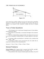
is safety (see Figure 16.1).
Figure 16.1
The author and
fellow climber Steve
work together to
install a new
multiantenna
bracket. Cooperation
and teamwork is a
must on the tower
and between tower
and ground crews.
Safety equipment
and procedures are
the highest priority.
Be Safe!
None of what we do with wireless networking or other personal or
work projects is worth dying, getting injured, or damaging or losing
equipment. OK, you are sitting at home comfortably thinking you
are going to “whip up” a quick antenna mount to share your wireless
local area network (WLAN) with a neighbor and this death thing
comes up suddenly. You wonder, why is he telling me this?
Stupid things happen!
Chapter 16
282
Working above ground level, and sometimes at ground level, can
be hazardous—so hazardous that the Occupational Safety and
Health Administration (OSHA) requires specific awareness, training,
and in some cases, safety measures for anyone working on elevated
platforms—from ladders up to 2,000 foot radio towers. The rules are
not as applicable or stringent at home. After all, we routinely grab a
ladder to clean out the rain gutters, paint, change light bulbs, etc.
Going up on the roof gets a little more serious. Most are not flat; it
could be slimy or slippery from moss, algae, or moisture; the grit in
composition shingles does come loose; wood shake is brittle and
crumbles; clay and tile offer no slip protection; and asphalt and grav-
el flat-tops are sticky and flammable. So, working at heights is not
something anyone should take lightly.
Below are some things you can do while you work on your project
to really mess yourself or your equipment up and do a really lousy
job of looking after your safety and that of others:
■
Wear baggy, loose-fitting clothing.
■
Wear lots of metal jewelry, especially dangling chains around your
neck, metal bracelets, and lots of metal rings on your fingers.
■
Wear loose-fitting open-toe sandals.
■
Work alone.
■
Use a wobbly, old broken ladder.
■
Always stand on the top step of a ladder.
■
Keep the ladder as vertical as possible so that it can tilt back and
fall over easily.
■
Work near and grab power lines and other wires.
■
Work in the wind and rain at night.
■
Ignore and throw away all safety information.
Please do not do any of those things—you know better, you should,
or you will. Let’s review a list of some of the proper considerations
and practices you should follow:
■
Wear clothing that is tucked in, rolled up, and otherwise not going
to get caught on anything.
■
Wear no jewelry—at least not around your neck, arms, hands, or
fingers.
■
Wear hard-soled, closed-toe shoes with some grip or grid on the
bottom.
Installing Antennas
283
■
Work with at least one friend.
■
Use a ladder in good condition.
■
Never stand on the top step of a ladder.
■
Keep the ladder at a proper tilt. Stand up straight at the base of
the ladder, stretch your arm out, and grab a rung at shoulder
level. The angle should match this posture and arm position.
Adjust the angle so your arm stays straight and you can easily
reach the rung. This is the most comfortable, balanced, and safe
climbing position.
■
Stay away from and never grab power lines and other wires.
■
Work only on calm, dry days.
■
Read and heed all safety information.
These are the basics of common sense, with safety in mind. Think
of anything and everything you will have to do to get where you are
going, stay there and work for awhile, have adequate room away
from hazards like power lines, be patient, and consider what could go
wrong first—then avoid it.
Once you are mentally prepared to work safely, you have to con-
sider the safety aspects of your installation and wiring. Chances are,
you will be mounting your antenna on a metal pipe, er, mast and
that mast will be attached to the side of a wooden part of the struc-
ture, on a newly installed tripod attached to the roof, or the side arm
or leg of an existing radio tower.
The key element here is that you will be using a metal pipe, typi-
cally 5, 10, or 20 feet long. Where you place that pipe and as you
move it around should be at least the full length of the pipe away
from any and all electrical wires. It should also not be in a location
where it could fall onto any electrical wires below. That little yellow
and red warning sticker on many mast pipes and antennas is there
for a reason. Even skilled and experienced antenna installers have
suffered electrical shock, falls, or death from coming in contact
directly or indirectly with electrical lines. Power lines are obvious,
but even phone, TV cable, and other lines are susceptible to static
and lightning, and should be avoided. Yes, you are going to be put-
ting in new electrical cabling of your own, but you will of course
dress that properly, out of the way of other objects and wires.
If you are working on a rooftop or at an existing communications
tower, you will probably be near other antennas and cabling. Those
Chapter 16
284
antennas will have radio frequency (RF) energy applied to them. You
should be aware of and heed any RF safety restrictions posted at the
site, or find out about them from the site owner or communications
company that services the equipment.
The most common use for antennas at most commercial radio sites
and atop urban buildings is high-powered radio paging. It is not
uncommon for these antennas to be fed with 250 to 330 watts of RF
power at 900 MHz. This is definitely an unsafe power level to work
near, even if you are just passing by to get to another spot on the roof
or tower. Rooftop owners should ensure that these antennas are
placed far enough away or high enough from where workers will be.
When working at a commercial tower site and climbing near or past
these antennas you are within your legal rights to reduce or disable
the transmitter to provide for safety—but do so only after contacting
the transmitter’s owner or service shop.
Certainly do not grab onto antennas, or climb in front of microwave
dishes. Unless you know for certain that a particular transmitter is
off-line and the antenna is not radiating, consider the RF signal hot.
Many of these systems are running on high power and provide high
gain, so there is a serious concentration of unsafe RF around most
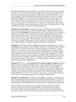
antennas and in front of microwave dishes (see Figure 16.2).
If there is a television or FM broadcast station transmitting near-
by, those stations may be required to reduce power while work is
being done. In one case, I was working on a tower at a TV station
running only 500,000 watts to an antenna mounted some distance
away. Its radiation pattern was directed away from where I was
working and the RF level was safe. The next time I returned to the
site, a new tower and antenna had been installed a further distance
away, placing the tower I was to work on in the radiation pattern of a
new 1.5 megawatt transmitter. It was no longer safe to climb this
tower without having the new transmitter’s power reduced. Pay
attention and know where you are, what has changed, and the rules!
Anywhere you are working, and especially when you are climbing
towers, special safety gear is required. On rooftops, the parapet or
ledge must be at least 42 inches tall to provide a barrier to falling
over; otherwise a fall protection harness must be used. When climb-
ing anything that places your feet over 6 feet above ground (or floor
or roof) level, you are required to wear and use fall protection
devices.
Installing Antennas
285
Figure 16.2
A typical large
microwave relay and
communications
tower with high RF
fields radiating in all
directions.
For most of us, this means an OSHA-approved full body harness, a
fall protection strap with shock absorber, and positioning lanyards to
secure us while working in one place, and of course a safety helmet,
with chin strap to keep it with you. This precludes the use of recre-
ational climbing equipment from the local sporting goods store,
including those wonderful colored aluminum carabiners. Recreation-
al equipment is not OSHA or American National Standards Institute
(ANSI) certified and does not have adequate load ratings. Save the
carabiners and nylon straps for equipment bags, but not for use as
personal protection (see Figure 16.3).
Chapter 16
286
Figure 16.3
The author strapped
in while climbing a
tower at 200 feet
above the Sierra
Nevada. Many
towers do not have
ladders to climb, so
you have to have
excellent “monkey
bars” skills to get
anywhere. (Do not
try this at home.
Hard hat removed
for clarity.
Professional climber
on closed tower.)
Do not free climb! OSHA and common sense dictates that you
must have two points of secure protection at all times—except while
transitioning from one secure point to another—and then one protec-
tion point must always be attached. Your safety equipment and those
attachment points must be rated for 5,000 pounds of load. If you are
going to rescue an injured or trapped climber, the protection points
and rescue gear must be able to handle 10,000 pounds. This is seri-
ous stuff!
The equipment is not all that is required to be certified as safe—
climbers must be OSHA certified for communications tower (or
equivalent elevated platform) work—easy enough to do if you can
find someone to certify you. Further, most communications sites
require liability insurance to cover any loss, damage, or injuries that
may result from your actions or inactions. Accidents happen, but
someone does have to pay for them. Also, your personal medical
insurance may not cover you if you are injured in doing this type of
work. It also pays to be in reasonably good physical condition (tread-
Installing Antennas
287
mills, stair climbers, and pull-ups are good practice for climbing) and
learn to pace yourself for climbing work. Climbing itself is only half
the job. You still have work to do when you get up there. Heavy sun-
screen and ample hydration are also highly recommended.
If you will be climbing a tower or working on a rooftop, chances
are you will not be carrying all of your tools and equipment with you,
but will have them hauled up on load lines, preferably through a pul-
ley, with someone on the ground handling the weight. This puts
them at risk because they are working below you and with things
that are moving above them. A safety helmet is required. Securing
loads adequately and without any fancy knots or wrappings is a
must. When the ground crew is not actively helping to do work, they
should step away from the tower, outside of the “drop zone”—an area
around and below the tower where things are likely to fall, account-
ing for wind as well.
Boy Scouts and Mariners Need Not Apply
There is nothing worse than being the climber on the tower and hav-
ing an antenna hauled up to you that has so many trick knots and
loops around it that you cannot safely get the equipment untied and
mounted. If you see bits of rope left on antennas and mounting hard-
ware on a tower, that is a clear indication that someone screwed up.
Simple loops at the top and bottom of piping and antennas are recom-
mended, as are clips or “beaners” to attach tool bags to hauling ropes.
Ground crew helpers need to think a little differently than when
tying a Christmas tree to the roof of the family sedan—you are tying
for someone else. The climber and helper(s) should work out these
techniques on the ground in advance. Plan the job and what will
happen when. Plans are subject to change as the climber advances
up a tower, checks the terrain around him, and discovers wind or
other issues that have to be worked around. Work together to consid-
er possible alternative plans in advance. Positively, fully, and ade-
quately communicate anything and everything that is or will happen
with positive acknowledgment on both ends. It’s lonely on the tower,
and the climber is almost totally dependent upon helpers to be able
to work efficiently and safely. If you do not communicate fully, the
wrong things will happen. Consider using high-quality two-way
radios (and not the dime-store FRS radio either; the RF signals at
Chapter 16
288
most communications sites will render cheap radios unusable) to
coordinate efforts beyond shouting distance.
Last but not least—what goes up must come down—and eventual-
ly does. The following picture (Figure 16.4) is the aftermath of a fall-
en tower, one I have climbed and worked on. (No, the damage is not
my fault.) Standing about 15 years or more, this tower gave in to 60+
MPH winds during a late winter storm in Northern California. This
tower looked and was safe for the most part and was not suspected of
suffering damage in the winds it is normally exposed to.
Figure 16.4
High winds broke
this communications
tower in half. The
structure at the right
is a temporary tower
erected to maintain
communications until
repairs to or
replacement of the
existing tower could
be done.
Aside from age or rust, the contributing factor to the demise of
such towers, normally able to withstand 120 MPH or higher winds
for short periods of time, is the amount of stuff mounted above criti-
cal structural points. The tower itself presents a wind load factor—
that means stress applied laterally to the structure by wind pushing
on brackets, pipes, cross-braces, etc. Anything added to a tower pres-
ents more wind load. Most cylindrical and exposed dipole antennas
Installing Antennas
289
add relatively little wind load by themselves, but several of them
begin to add up. Panel antennas and dishes add 2 to 10 times the
amount of wind load of other conventional antennas. Tower site own-
ers and installers must be very careful to balance wind load factors
versus antenna placement. Of course everyone wants their antenna
at the top of the tower, but that may not be safe, prudent, or reason-
able, due to wind load or physical mounting issues.
Common sense must rule in the absence of anything else. Look
around. Listen carefully. Be aware. Pay attention. Think about every
action and potential reaction. If something looks, feels, or sounds like
it might break loose and fall, it probably will. Stay away from trou-
ble spots and be safe!
Materials and Techniques
The number two concern about antennas is doing it right. Why both-
er if it is not going to work and last longer than a day, a week, or a
month. A good friend provided an excellent motto for this and other
projects: The price of quality only hurts once.
Potato chip can antennas do not survive in the rain and winds.
Anything left outdoors for any period of time is going to be vulner-
able to and suffer from the elements—wind, rain, dust, sunlight,
salty air, perhaps even snow and ice. Few of us can afford the money
to replace and the time to reinstall damaged antennas or feedline.
Face it, an antenna is not like your keyboard, mouse, monitor,
computer, or router. Once an antenna is installed, it is often forgot-
ten—as it should be, if you used the right materials and installed it
all properly. Select the best material you can find for the job at hand,
and for as long as you expect it to last. In some cases, select even bet-
ter materials to give yourself a margin of safety and longevity. Think
about what an antenna system is and what it must endure through-
out its expected lifetime.
An antenna system is made up of several pieces of hardware—bits
of metal, plastic, cable, nuts, bolts, cable ties, tape, and connectors.
Most of these pieces are left outdoors to the whim of the elements.
The hardware itself is not considered visually appealing or suitable
to most people. Any visual appeal or tolerance diminishes quickly
Chapter 16
290
because of the elements, as may the performance, strength, or safety
of what you have installed. Corrosion and wind are your antenna
system’s two worst enemies. Corrosion plus wind makes for an
unsafe system.
The Proper Tools and Supplies
The materials you choose and how you install them can minimize the
effects of either and make for a longer lasting, safer system. The
right tools and supplies make the installation go smoother, and make
it more secure and water-resistant, if not waterproof. The following
is a list of supplies that should be in your kit of items for antenna
installations and repairs:
■
Assorted combination wrenches with both open and box ends
■
Heavy duty wire cutters
■
Utility knife
■
3/16- to 1/4-inch wide black cable ties (not white, clear, or colored)
■
3M Scotch #33 or #88 electrical tape
■
3M Scotch #130 splicing tape
■
Spray can of cold-galvanizing paint
■
Small- to medium-sized wire brush
■
Power drill motor and assorted drill bits
Mast and Antenna Installation Materials
If you have an existing TV or other antenna mast on your roof that
you can install your wireless antenna on, check it for damage, rust,
and secure fastening. And if guyed, make sure the guy wires and
clamps are in good, nonrusted condition. Sometimes replacing what
is there is of benefit to everyone. Rusty bolts, pipes, wires, and
clamps are unsafe, insecure, and are possible sources of RF noise
and interference. If the existing items are in relatively good condi-
tion, then wire-brush and overspray all of the joining parts, clamps,
and bolts with cold-galvanizing spray paint to protect and make
them last longer. Make this a routine.
If you are simply going to install a small omnidirectional antenna
for local use, you can probably get by with a set of small clamps to
Installing Antennas
291
fasten the antenna to a vent pipe or a chimney mount kit (if allowed
by local ordinance). If you need to elevate your antenna well above
roof level, I do not recommend chimney mount kits and certainly not
strapping a mast to a vent pipe. Chimneys are not designed or
intended for additional lateral loads, and a mast and antenna can
add considerable side load and leverage to them. Vent pipes are not
well secured in the walls, and are usually not thick enough to handle
any additional loading.
With this in mind, you are limited to using roof-cap mast base
plates and guying (tying off) your mast or installing a tripod atop the
roof. You can find adequate materials at local electronics outlets and
hardware stores, though I prefer to use galvanized steel pipe or
heavy duty mast material in place of thin-wall painted steel “TV
mast” sections. The latter crimp, crush, bend, and rust quite easily.
Yagi and dish type antennas present a higher wind load than omni-
directional antennas, so your choice of materials has to account for
this. Antennas for 2.4 and 5 GHz are much smaller than most odd-
ball-looking TV antennas, but we would like the installation to
reflect that we know what we are doing—quality, long-lasting work-
manship using good materials. With that in mind, the following
materials are typical and recommended for good long-term home
rooftop installations:
■
Thick-wall galvanized steel pipe, 1-1/4 to 1-1/2 inch diameter,
water pipe or heavy conduit, but not electrical metallic tubing
■
Heavy-duty tripod for pitched roof mountings
– 3-foot model for 5- to 10-foot mast pipes; 5 feet tall for 20 foot
pipes
– 3-foot model fine for 20-foot mast pipes if you add guy wires
■
Tilt-over roof anchor plate for mast-only (no tripod) installations;
mast to be guyed
■
1/8- to 3/16-inch galvanized steel guy wire (for a 20 foot mast with
three guy wires, you need 100 feet)
■
Guy wire anchor hooks—to secure the wires from the mast to the
roof
■
8 foot long 1/2 inch diameter copper ground rod
■
#6 to #10 stranded copper wire (green insulation preferred)
■
Assorted grounding clamps to suit the mast size and ground rod
■
Galvanized or rust-resistant clamps, nuts, washers, and bolts
Chapter 16
292
■
5/16-inch, 5- to 6-inch long lag bolts to secure base to roof, or 10-
inch long carriage bolts for through-roof to backing plates
■
2ϫ4 lumber stock to use as back-plating for fastening the tripod or
base plate to the roof
■
Roofing caulk to seal holes and apply under mounting plates as
they are set
The rooftops of commercial and nonresidential buildings may
require significantly different materials. For instance, it is not
uncommon to anchor a tripod to a set of 2ϫ6 or 2ϫ8 boards and hold
it onto the rooftop with cinder blocks. The parapet or ledge of com-
mercial buildings or the side wall of an elevator penthouse will likely
require special brackets and concrete anchors to adequately secure a
shorter mast.
Commercial radio towers come in all sizes and shapes—some
with 1 inch round legs, some with 1- to 4-inch angled steel pieces,
and large hilltop towers designed to carry several microwave dish-
es have 4- to 10-inch diameter legs at the bottom sections, scaling
back to 2- to 4-inch diameter legs at the top sections. You are typi-
cally required to use heavy-gauge galvanized steel hardware
intended for communications towers. You will not find suitable
mast or antenna mounting hard for commercial towers at local
hardware stores. For these items, consult a professional communi-
cations or tower facility to locate a vendor for commercial brackets
and clamps.
In any case, where a metal item extends above the rooftop, there
is the potential for lightning discharges, thus the ground rod, #6–#10
wire and clamps. For homes and other low level (one- or two-story)
buildings, you should run your own ground wire and drive a ground
rod to bleed off any static and avoid lightning strikes. If a ground rod
cannot be driven in or the roof is higher than three stories, you will
probably be able to find a common safety ground point or cold water
pipe to secure the ground wire.
Grounding is important not only for lightning protection, but
also to help reduce the overall RF noise level at locations with sev-
eral radio systems. Grounding also bleeds off any static or induced
electrical currents that could cause injury to workers or perching
birds.
Installing Antennas
293
Good Neighbor Policy
and Local Regulations
Part of preparing for the installation of any antenna is figuring out
where to put it. Many homeowners association policies and local
ordinances prohibit the installation of antennas of any type, any-
where on your home or property. Others limit the height or place-
ment of antennas to minimize their apparent visual impact on the
local surroundings and architecture.
Barring local restrictions, it is best to follow a “good neighbor policy”
and voluntarily locate your antenna where it will have minimum visu-
al impact on your neighbors. After all, what looks good and works well
for you may not appeal to the grouch next door, or those who deter-
mine they are suddenly sensitive to or adversely affected by a few
microwatts of RF signal. Most homeowners have little choice. The
ridge of the roof runs sideways, parallel to the street, yielding maxi-
mum visual exposure. In this case, you have to figure out which neigh-
bor will be bothered least looking out the window—the one whose
kitchen window would be near the antenna or the other one whose
bedroom window (typically with curtains closed) would be closest.
If restrictions prohibit you from installing an antenna so that it
can be seen from the street, you will have to determine a mounting
position and method behind the peak of the roof line. If you are
lucky, you may be able to tuck the antenna in behind the chimney for
maximum height and discretion.
Best Practices and Techniques
If you are able to and have decided to use a tripod or tilt-over roof
plate to mount the antenna onto, you must find a location to place
the mounting surfaces directly above rafters and beam so that lag
bolts have something to bite into to be effective. If you cannot find
such a place easily, or you prefer a slightly more secure fastening
method, you can find a place to set the mounting feet between or on
either side of rafters or beams, and use a backing plate inside the
attic area to span across sets of rafter. Either method suggests that
you survey the inside of your attic (the bottom side of your roof) for
Chapter 16
294
obstructions, electrical wiring, or anything else that might interfere
with your antenna mounting.
You may want to begin working from within your attic anyway to
place and drill at least rafter-locating pilot holes from the inside out
for better placement accuracy. Use a 1/8-inch drill bit for the pilot
holes—no sense in making your roof look and leak like Swiss cheese.
Remember, any hole you drill should be closed up and sealed with roof-
ing caulk as soon as possible to avoid water damage. If it’s not obvious
yet, this type of work is best done with two people working together,
one inside and one outside to coordinate mounting alignment, etc.
After you have selected and prepared your mounting method of
choice, set the mount in place. Check the alignment and adjust as
necessary. For tripod mounts, you should set the mast in place and
check to be sure it is level in all directions before finalizing the
mounting location. Drill the holes for the lag or carriage bolts and set
the mounting in place. When you are ready to secure the mounting,
first lift up the mounting plate or foot and liberally apply roofing
caulk to the roof where the mount will set down. This will help seal
the hole and the area around it to prevent water leakage. Finally, set
the bolts, tighten, and check for security. Even though most of the
weight will initially be downward, the mounting should be secure
from lateral movement due to wind, and to make sure water cannot
seep in between the plate/foot and the roofing material.
With the mounting set in place and secured, you are ready to set
the mast and antenna. Unless you are 7 or 8 feet tall and able to
reach the top of the mast to install and aim the antenna if necessary,
you should mount the antenna onto the mast first before setting the
mast into the mounting.
In very rare cases, such as the installation of my Sprint Broad-
band wireless service “pizza box” antenna, my location and nearby
trees required that Sprint’s technicians install a 35 foot push-up
mast atop my roof. The order of installation was the same for the
mounting plate; then the mast was put up and guyed at the first 10
foot level. Once the mast was securely guyed, a ladder was brought
up and placed against the mast to allow a technician to climb up,
attach the antenna and feedline to the top section of the mast, and
then attach guy wires to the three remaining push-up sections. The
top/smallest section was raised first and locked into place; then the
second section was pushed up and locked, and finally the third. As
sections were pushed up, the feedline was secured to the mast with
Installing Antennas
295
cable ties every 12 to 18 inches. Aiming the antenna in the direction
of its main tower was done by turning the raised mast sections care-
fully. If you can picture this event in your mind, yes, it was as risky
as it looks. I am glad I was just watching, and now I know how to
take this assembly down when the time comes.
Moisture is an enemy of all things electrical, and especially RF
signals. A water-tight seal of all connections is a must for a trouble-
free installation. Part of the task of attaching the antenna to the
mast is to seal the connection of the feedline cable at the antenna. If
you have a Yagi-type antenna with an end-fed connection, you can
seal the connectors with tape (Figures 16.5 and 16.6) or use a sealing
boot (Figure 16.7).
Figure 16.5
Apply a layer of high-
quality electrical tape
(3M Scotch #33 or
#88), fully covering
the connector to the
end of the threads
and beyond. This
layer keeps the
connector clean and
prevents
contamination and
‘gunk’ from the next
layer. Slicing and
peeling off the
sealing layers to
service the
connection is also
much easier.
If you are using a Yagi antenna that is side-fed parallel to the
boom of the antenna, it will not be easy to use tape, so a sealing boot
is required. Most sealing boots are made of a heat-shrinkable tubing
filled with an electrically safe moisture-proof caulking material.
Sealing the boot requires the use of a heat gun or propane torch to
shrink the tubing so it adheres firmly around the connector and the
caulking oozes out from the edges.
Chapter 16
296