Surface Engineering of Metals - Principles, Equipment and Technologies Part 12 pot
Bạn đang xem bản rút gọn của tài liệu. Xem và tải ngay bản đầy đủ của tài liệu tại đây (662.78 KB, 26 trang )
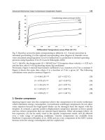
Fig. 5.18 Orientation values of thickness and hardness of some superficial diffusion layers.
In addition to surface hardness (the measurement of which was intro-
duced to industry as late as the 20th century) it is important to know the
hardness of structural elements of the particular zones of the superficial
layer, e.g., grains and structural components, especially on cross-sections.
This last parameter, known as microhardness, came into use only after
World War II [28].
Fig. 5.19 Hardness profile: a) Nitralloy 135M, hardened and tempered to 30±2 HRC;
1 - glow discharge nitrided at 520°C for 9 h; 2 - implanted by nitrogen ions with energy
of 100 keV and ion dose of 2·10
17
ions of N
2
+
per cm
2
; 3 - electron beam hardened with
power density of 2230 kW/cm
2
and exposure time 0.74·10
-4
s; 4 – laser hardned with
power density of 1.4 kW/cm
2
and exposure time of 0.13 s; b) 18HGT grade steel, gas
nitrided at 530°C for 36 h
© 1999 by CRC Press LLC
Hardness (microhardness) is one of the most basic, universally accepted
properties of materials, especially of metals and their alloys, easily measured
by various methods, and connected with many other properties of the super-
ficial layer, e.g., wear resistance, strength, residual stresses, plasticity. Usu-
ally, the higher the stress loading to which the part is subjected, the higher
should be the hardness of the surface. Unfortunately, a rise in hardness is
often connected with a rise in brittleness.
Hardness depends on the type of material and its structure which, in
turn, depends on treatment, especially strain-hardening, heat and thermo-
chemical treatment (Fig. 5.19). The hardness of crystalline bodies depends
on the limit of elasticity under compressive loading and on the modulus
of elasticity. The microhardness of superficial layer zones may change
during service, especially during wear, as the result of microstructural
changes caused by surface tempering, secondary hardening (grinding
burns), the breakdown of residual austenite and other factors [21,32].
5.7.3.4 Brittleness
Brittleness is a material property, consisting of permanent partition of
material under the influence of internal or external forces. The partition
begins at the tip of the propagating crack and is formed without the pres-
ence of any significant plastic deformation. Brittleness depends on the
type of material, its phase composition, structure, etc. and on external
factors such as stress distribution, method of loading, temperature, chemi-
cal composition of the environment and others. Usually, brittleness oc-
curs in solids within certain temperature ranges [26]. The majority of
materials exhibit brittleness at ambient temperature (so-called cold short-
ness); others, as e.g., unalloyed open-poured steel, exhibit greater brittle-
ness at elevated temperatures (so-called hot shortness). Metals may ex-
hibit different types of brittleness, e.g., the already mentioned cold short-
ness and hot shortness, hydrogen embrittlement (caused by excessive dif-
fusion of hydrogen into the metal), pickling embrittlement or embrittlement
caused by electroplating of metal objects, temper embrittlement, blue brittle-
ness, etc.
In the case of superficial layers and coatings, brittleness is an undesirable
effect, e.g., brittleness of superficial layers after diffusion, caused by excessive
concentration of saturating element, like nitrogen. Often, although not al-
ways, brittleness is connected with hardness: the higher the hardness, the
greater the brittleness of the layer.
A property opposite to brittleness is ductility - the susceptibility of
metals to permanent plastic deformation without the formation of cracks.
Ductility is one of the basic characteristics of the metallic state. Often the
term “ductility” is used as a synonym of plasticity but it means a qualita-
tive, non-measurable characteristic, strongly dependent on structure, pro-
cesses occurring at the atomic level and on the type of slip.
Usually it is desired that hard but not brittle layers be formed over a
ductile core [26, 27].
© 1999 by CRC Press LLC
5.7.3.5 Residual stresses
Types of residual stresses. In all materials subjected to extraneous effects - be
they mechanical, thermal, chemical or a combination of any or all of them -
there occur non-uniform volume changes, both reversible and irreversible,
causing the formation of stresses. Stresses describe the state of internal forces
and moments of forces, brought about by the interaction, in a given locality,
of two parts of the material, situated on either side of an apparent cross-
section, the forces in question acting on a unit area of the cross-section.
After the removal of external effects, reversible changes (elastic defor-
mations) undergo atrophy, along with stresses caused by them. However,
some irreversible changes (plastic deformation) remain in the material,
along with stresses caused by them which are referred to as residual stresses
[33].
Residual stresses, in earlier times referred to as rest or final stresses,
are those which are in mutual equilibrium within a certain zone of the
material and which remain after the removal of external loading. Depend-
ing on the zone where this equilibration occurs, the following types are
distinguished:
1) according to the classification by E. Orowan [34], two types of residual
stresses include:
– macrostresses - formed as the result of any external loading, and
balanced out in the entire volume of the body. They are regarded as the
result of the joint, average interaction of microstresses. A definition of this
type assumes the material to be homogenous, i.e., having isotropic proper-
ties;
– microstresses - formed as the result of heterogeneity of the material
(blocks of grains, single grains), which usually generate a non-homo-
genous stress field, often connected with texture and therefore exhibiting
preferred orientation (so-called stress-texture) [29];
2) according to the classification by N.N. Davidenkov [34, 35] three types
of residual stresses are distinguished (Fig. 5.20):
– stresses of the I
st
kind, termed macrostresses (body stresses), caused
by the mutual interaction of macroscopic-size zones of the material, bal-
ancing out within volumes of the same order of magnitude as the object,
within the limits of the entire superficial layer, in zones of dimensions
approximating those of the superficial layer or in major zones of the su-
perficial layer (e.g., in a zone with a very big number of grains). They are
formed when external effects in the form of, e.g., mechanical loading causes
non-uniform plastic deformation or as the result of thermal effects, caus-
ing non-uniform expansion of neighboring macrozones. For this reason,
they were once referred to as thermal stresses. The conservation of body
continuity requires the formation, between such macrozones, of mutual
interaction, tensile or compressive, which we call macrostresses [33].
Macrostresses are caused directly by non-uniform plastic deformation,
temperature changes, changes in the material structure or a combination
© 1999 by CRC Press LLC
times referred to as structural stresses. Microstresses often constitute the
result of the formation of a superficial layer. Their chief source is different
crystal orientation and the associated anisotropy of elastic and plastic
properties of the various crystals. Since after treatment (mainly deforma-
tion) the microstructure usually exhibits a definite texture, stresses also
exhibit a preferred orientation, called stress texture. Its final result is the
anisotropy of the material’s properties. Microstresses may be regarded as
the result of total, average interaction of submicrostresses;
– microstresses of the III
rd
kind, termed submicrostresses, balancing out
within the space of one crystal, thus within zones corresponding to the crystal
lattice parameters. They are treated as stresses of the material’s crystal lattice,
especially in zones with defects. In such zones the proper structure is dis-
rupted by the occurrence of own or foreign atoms in improper interstitial and
nodal sites or the existence of voids. Foreign atoms introduce into the lattice
their stress fields, nodal voids cause the absence of stress fields to balance the
fields from neighboring atoms. Stress fields from foreign atoms in nodal sites
also do not balance out stress fields from neighboring atoms. The energy of the
lattice in the vicinity of a defect is in all cases higher than its minimum value
corresponding to the state of equilibrium. The result of that is the stress field
around the defect. The range of stress fields is small due to the small range of
action of atomic forces and may reach several lattice spacings. Stress fields
around defects interact with atoms but only with the neighboring ones, upset-
ting them from their state of equilibrium [33, 35-37].
If an atom of gas, e.g., hydrogen, is introduced by diffusion into the
crystal lattice of steel, it generates around it compressive residual stresses
of the III
rd
kind. Next, as the result of desorption of gas molecules in the
internal discontinuities of microstructure, very high pressures are gener-
ated in such sites, giving rise to compressive residual stresses of the II
nd
kind. After the saturation of the superficial layer with this element it is
usual that a gradient of its concentration will occur (and along with it a
gradient of properties). The final result will be that residual stresses of the
I
st
kind will be generated between layers or between the superficial layer
and the core [38].
In the superficial layer there exist three kinds of residual stresses; they
are manifest predominantly as macrostresses. Micro and submicrostresses
affect the limit of elasticity of the material but have only a small influence
on its strength. They are added to stresses caused by external effects and
for that reason they determine the moment of exceeding of the material’s
strength, manifest by the formation of microcracks. Submicrostresses may
be the cause of high hardness and strength of metal alloys [33]. Indepen-
dently of the kind of stresses, the result of their action is the same - they
always induce defects and elastic deformations of the crystal lattice. Fur-
ther on in this book the term “residual stresses” should be understood as
residual stresses of the I
st
kind.
Each surface treatment in which the limit of elasticity is exceeded by any
element of the superficial layer or core structure leaves behind a trail in the
© 1999 by CRC Press LLC
form of residual stresses, especially those of the I
st
kind. In the majority of
finished machine parts and structures there exist residual stresses left be-
hind by treatment or assembly operations.
Residual stresses are characterized by their sign (“-” compressive and
“+” tensile), their value, distribution, gradient and depth of penetration.
Factors causing the formation of residual stresses. Such factors can
usually be classified as being of three kinds:
– mechanical, stemming from non-uniform plastic deformation of su-
perficial layers during mechanical cold work. They are accompanied by
non-uniformly distributed and interconnected processes of force action,
reorientation, refinement, expansion or contraction of structural compo-
nents. Macrodeformations give rise to reorientation of structural compo-
nents in layers situated closer to the real surface relative to deeper situ-
ated zones. Microdeformations, on the other hand, reveal themselves within
the volumes of separate components, due to their refinement into frag-
ments and blocks and to mutual elastic-plastic interaction of neighboring
grains. Resulting from that is local increase or decrease in material den-
sity, enhanced by the movement of dislocations, their distribution and
kind [37]. Plastic deformation due to cold work causes changes in mate-
rial density (a rise in volume of approximately 0.3 to 0.8 [21]), conducive to
the rise of compressive stresses. Plastic stretching of the superficial layer by
forces of friction and by machining chips also causes the formation of com-
pressive stresses. Residual stresses caused by mechanical factors are some-
times termed mechanical residual stresses;
– thermal, caused by thermal expansion of the material and stem-
ming from non-uniform heating or cooling of various layers of the ma-
terial (macrodeformations) or of its particular fragments (microdefor-
mations). During heating, especially if it is non-uniform, there occurs
non-uniform thermal expansion causing plastic deformation which pre-
vails all the way up to melting point. In the liquid state, the volume of
all metals (with the exception of bismuth and antimony) is smaller
than in the solid state. Fig. 5.21 shows a diagram of the formation of
residual stresses using water quenching of 100 mm dia. heated steel
bar as an example [39, 40]. Upon heating, surface temperature is usu-
ally slightly lower than that of the core. With progress of cooling time,
the difference between surface temperature (curve S) and core tempera-
ture (curve C), in other words - the temperature gradient - rises. The
material of the superficial layer and of layers situated deeper dimin-
ishes in volume with the progress of the cooling process, shrinking
(linear changes of approximately 0.5%), causing the formation of ten-
sile stresses (curve 1). At the same time compression of the still hot
core, gives rise to compressive stresses there (curve 3). The temperature
gradient between surface and core rises until it reaches point M. The
maximum temperature difference (approximately 600 K) corresponds
to maximum tensile stresses at the surface and maximum compressive
© 1999 by CRC Press LLC
panied by a simultaneous process of stress formation. The stresses are com-
pressive if the specific volume is increased and tensile if decreased. In turn,
all volumetric changes within the volume of a given component are accom-
panied by changes in neighboring zones [37]. Greatest residual stresses are
formed during hardening, caused by the transformation of austenite to mar-
tensite which proceeds at a very high linear rate (in ferrous alloys the rate of
growth of martensite nuclei is approximately 33% that of the speed of sound
in a crystal). Martensitic transformation in the heated material occurs as the
result of quenching at a known rate of heat extraction, highest at the surface,
causing a volumetric increase in the superficial layer. When the carbon con-
tent in martensite is 1%, volume increase of martensite relative to austenite is
approximately 4%. In the slower cooled core, martensitic transformation is
retarded. The core is subjected to stretching, causing compressive stresses at
the surface. Next, the onset of martensitic transformation in the core causes
the stretching of the outer layers which were hardened earlier and, in conse-
quence, the compression of the core. Changes in specific volume which are
due to structural transformations are greater than those brought about by
thermal expansion. Stresses caused by these factors are termed structural
residual stresses.
Other examples of external forces causing the formation of residual
stresses with varied value and range of action may be, besides pressure
(mechanical stresses) and temperature (thermal and structural stresses),
chemical interaction (e.g., formation of chemical compounds by atoms
introduced through diffusion and substrate atoms) and physico-chemi-
cal (e.g., implantation with the formation of chemical compounds).
Through the change of chemical composition, such interaction causes
changes in the specific volume of the material or in the coefficient of
thermal expansion. As an example, the saturation of iron and its alloys
with nitrogen increases volume and decreases the thermal expansion
coefficient of the saturated layer relative to that of the core which causes
compressive stresses to be set up in the layer and tensile stresses in the
core.
Usually, residual stresses are formed as the result of joint interaction of
several forces (causes) and their separation is usually difficult. For ex-
ample, during hardening, when the effects of thermal and structural stress
formation overlap, structural stresses tend to either raise or diminish ther-
mal stresses, depending on the size and shape of the element’s cross-
section plane, rate of heat extraction and steel hardenability. Tying in the
above to point U in Fig. 5.21 [40] the following can be stated:
– structural stresses raise thermal stresses if they are formed in the core
before and in the superficial layer after reaching point U and vice versa;
– structural stresses across the entire cross-section or after passing
through point U counteract thermal stresses;
– greatest compressive stresses in the superficial layer and tensile in
the core are formed when transformation in the core occurs before and in
the superficial layer after passing through point U.
© 1999 by CRC Press LLC
When, after removing the external forces, residual stresses prove to be
only slightly less than the material’s strength, the material may deform, warp,
suffer delamination or exfoliation. If they prove to be greater, the material
will crack.
Residual stresses are superimposed on operating stresses, induced by
external forces (see Fig. 5.44).
– They can be added to them, resulting in the material being destroyed
already under operating stresses, lower than material strength, sometimes
under quite small loads. Residual stresses can also cause the material to
crack spontaneously [37]; it is said that residual stresses reduce material
strength. In the superficial layer, these are usually tensile stresses.
– They may be subtracted from operating stresses, resulting in destruc-
tion of the material only when operating stresses exceed the material’s
strength; it is then said that residual stresses raise material strength. In
the superficial layer these are usually compressive stresses.
Residual stresses are formed in the superficial layer and in the core.
Usually, the value of residual stresses is greatest in the superficial layer and,
the greatest stress gradients are located there, especially at the interface be-
tween the superficial layer and core (Fig. 5.22).
Residual stresses in the superficial layer usually occur in zones of tex-
ture, plastic deformation, and elastic deformation, but it is in the textured
zone that they assume their highest values. Their distribution and value
depend on the type of material and its three-dimensional and metallo-
graphic structure, on strength and thermal characteristics, on external
factors (e.g., rate of heat extraction) and on the associated strain-hardening of
the superficial layer, as well as on wear resistance.
General functional expression of residual stresses. In the broadest
sense, residual stresses
σ
w
may be expressed by an implicit function of the
most important, mutually interacting parameters in the form below:
σ
w
= f (m, t, k, o) (5.16)
where: m = f
1
(c, w, f, ch, s) - is the function of the primary material (core,
superficial layer, coating), described mainly by its properties: c - thermal
(especially: thermal conductivity, thermal expansion, specific heat); w - me-
chanical (especially strength: Young’s modulus, Poisson ratio); f - physi-
cal (e.g., ion implantation); ch - chemical (especially: chemical composition,
formation of chemical compounds of diffusing atoms with substrate atoms); s
- structural (especially: roughness and valley bottom radius) and metallo-
graphic (especially grain type, size and orientation, defects); t - technology of
formation of superficial layer or coating (type, number, sequence and param-
eters of treatment operations; temperature, temperature variation rate, tem-
perature gradient, pressure, loading, feed rate, energy, element concentration,
etc.); k - shape and size of component in which residual stresses are mea-
sured; o - interaction of core with superficial layer or coating.
© 1999 by CRC Press LLC
Fig. 5.23 Distribution of residual stresses, resulting from: a) diffusion chromizing of
D2 grade steel; b) TiC coating of D2 steel; c - boriding of 1045 steel; designations: B -
boriding; Cr - chromizing; Ti - TiC treatment; H - hardening; T - tempering. (From
Janowski, S. [41]. With permission.)
In the absolute sense, a given value of residual stresses when all other
parameters are equal depends heavily on the method of measurement.
Numerical values of residual stresses, obtained by different measurement
methods, may differ by several to several tens percent. In certain cases
© 1999 by CRC Press LLC
differences exceeding 100% and even results with opposite signs may be
obtained [41, 42].
Residual stresses in a superficial layer directly affect the layer’s cohe-
sion but their action may also be of an indirect nature - by forcing the
migration of atoms with small diameters (e.g., hydrogen, carbon, nitrogen,
boron) through the crystal lattice of the host material. The force exerted
by stress gradient on an atom in an interstitial position is, admittedly, not
big in comparison with the force exerted by a concentration or tempera-
ture gradient. However, local stresses may cause migrations of interstitial
atoms to sites preferred by geometry or thermodynamics (vacancy clus-
ters, dislocation lines, grain boundaries and stacking faults) causing sig-
nificant local stresses, favoring the initiation of cracks [38].
When knowingly shaping the properties of the superficial layer, it is
endeavored to obtain, as the final result, compressive residual stresses in
the superficial layer, while in the core - tensile residual stresses with a
small gradient. Compressive stresses in the superficial layer may even
attain a value equal to approximately 50% of the material’s ultimate strength
[37].
The value of compressive residual stresses obtained as the result of sur-
face diffusion treatments may even reach 2400 MPa (Fig. 5.23) [41]. As an
example, the value of compressive stresses in nitrided layers on low alloy
nitriding steels and on high alloy structural steels may reach 900 MPa [38].
In the case of mechanical strain hardening, the depth of penetration of
stresses is usually greater than the depth of hardening even by several
tens percent. With a rise of stress value at the surface, the depth of their
penetration diminishes [37]. The value of residual stresses rises when me-
chanical strain hardening is coupled with heat treatment of thermo-chemi-
cal treatment (Fig. 5.24).
Generally, with a rise in the strength of the mechanically strain-hard-
ened material and in the strain-hardening parameters (mainly, the loading
force), residual stresses in the superficial layer increase. Their value, depth of
penetration and character of distribution may all be controlled by treatment
operation parameters. In almost all cases the formation of compressive stresses
in the superficial layer causes a rise of fatigue strength (with tensile stresses
the effect is opposite) and hardness, wear resistance and corrosion resis-
tance. A greater degree of plastic deformation causes an increase in residual
stresses and in fatigue strength.
Regardless of the root cause of formation of residual stresses, their value
and distribution affect strength properties, especially fatigue strength, resis-
tance to dynamic loading and to brittle cracking (see Section 5.8.1), as well
as tribological properties, especially contact fatigue (see Section 5.8.2) [42].
A particularly significant effect of residual stresses on mechanical prop-
erties, especially fatigue, is revealed in the case of superficial layers con-
taining technological or structural flaws, surrounded by stress concentra-
tions.
© 1999 by CRC Press LLC
In surface shaping treatment processes the following types of technologi-
cal residual stresses are formed:
– quenching stresses, caused by volumetric changes due to predominantly
phase transformations but also to heating and cooling,
– casting stresses, caused by solidification and cooling,
– welding stresses, caused by phase transformations and thermal ex-
pansion.
In all superficial layer shaping treatment operations, the character and
value of technological residual stresses change during the technological
process (see Fig. 5.10) and from process to process [13] in the following
manner:
– at first, the superficial layer contains only primary (initial) residual
stresses, created during the previous treatment operation (in the steel-
making process, forging, casting, cold forming or heat treatment) and
being the net result of a superimposition of effects which had occurred
prior to the considered operation;
– under the influence of the treatment operation considered, techno-
logical residual stresses are created which, when added to initial stresses,
become resultant stresses;
– resultant stresses of the considered treatment operation constitute, at
the same time, the initial stresses for subsequent treatment operation.
Technological residual stresses do not constitute a value which is con-
stant in time or for any location. Under the influence of external forces
occurring during storage or service, technological stresses become service
stresses and their value and distribution change, due to processes of relax-
ation and redistribution (Fig. 5.25).
Fig. 5.25 Redistribution and relaxation of residual stresses during service: a) in 1045
steel, induction hardened and subjected to fatigue testing. (From Janowski. S. [42].
With permission.); and b) structural steel, subjected to wear testing. (From Svecev,
V. D . [43]. With permission.); 1 - before test; 2 - after test.
© 1999 by CRC Press LLC
5.7.3.6 Absorption
Absorption (from Latin: absorptio - imbibition) is a physico-chemical pro-
cess of permeation of mass, consisting of the taking up of a constituent,
usually a gas mixture called absorbate, by a liquid or a solid (called absor-
bent) and uniform dissolution of the former in the entire mass of the latter.
This is a volumetric process, i.e. the entire volume of the absorbent uni-
formly takes up the absorbate. The effect of volumetric absorption is often
accompanied by diffusion of the absorbate. In a simplified manner, absorp-
tion is treated as dissolution in a liquid (for that reason, the amount of
equilibrium absorption is described by solubility) or - in a more general
way - as the permeation of one phase into another in a diffusion process.
Absorption is often accompanied by chemical reactions, e.g., in pack car-
burizing of steel, carbon from the carburizing powder pack reacts with
oxygen contained in pores of the carburizing mixture, forming carbon mon-
oxide CO which breaks down at the steel surface, due to its catalytic action:
2CO ♦ CO
2
+ C, giving off atoms of nascent carbon, capable of diffusing
into the steel. In gaseous carburizing, some atoms are obtained from the
breakdown of hydrocarbons [39]. The effect of absorption is widely used in
the chemical and related industries in order to separate a harmful or a
valuable component out of a gas mixture or to combine the gas with an
absorbent to obtain a compound, an extraction of a substance dissolved in
a liquid (e.g., in water) by another liquid which does not mix with the
solvent, etc. In surface engineering, absorption of gases by metals and al-
loys is utilized chiefly in order to saturate the superficial layer by the dif-
fusing element. The course of absorption is, in this case, dependent on the
difference of chemical potentials in metals and alloys on the one hand, and
the surrounding environment (gas atmosphere, salt bath, powder pack, paste)
on the other. Absorption also plays an important role in tribology.
5.7.3.7 Adsorption
Adsorption (from Latin: ad - at, sorbe - to absorb) is the process of attraction of
substances (gases, vapors, solids in solution, ions and liquids) and their
collection at the surface of solids and liquids, at the interface between solid
and gas or liquid and gas. Adsorption is manifest in changes of concentra-
tion of a substance in the boundary layer between two neighboring phases
and depends both on the properties of the adsorbing body (adsorbent), as
well as the adsorbed body (adsorbate). Greater adsorption is exhibited by
bodies with a developed surface (e.g., rough and porous) than by bodies with
smooth surfaces [9, 40-43]. Often, adsorption is treated as surface adsorp-
tion.
Adsorption may occur in static conditions - from a fixed volume phase
(static adsorption) and in dynamic conditions - from a flux of gas or
solution (dynamic adsorption).
A molecule from the volume phase, e.g., gas, having reached the surface of
the solid or liquid adsorbent is maintained there (or adsorbed) by
© 1999 by CRC Press LLC
Fig. 5.26 Adsorption at solid/gas; solid line - profile of substance concentration (i) vs.
distance from physically pure solid surface; dashed line - profile of substance concen-
tration vs. distance from solid surface in reference system; surface concentration
excess n
i
is represented by the shaded area. (From Oœcik, J. [45]. With permission.)
surface forces for a certain time, dependent on the character of the adsor-
bate and adsorbent, on temperature and pressure, and finally leaves that
surface or is desorbed. Commensurate with the saturation of the surface,
the rate of adsorption decreases while the rate of desorption increases.
When both rates are equal, desorption equilibrium is set.
Molecules of the adsorbate at the surface of the adsorbent form ad-
sorption layers.
We distinguish positive adsorption when the concentration of the sub-
stance is greater in the superficial layer than in the deeper phase, and nega-
tive adsorption when the concentration in the superficial layer is less than in
the deeper phase.
In most cases, positive adsorption of gases, vapors and dissolved sub-
stances occurs at solid surfaces. The molecules of a very volatile phase
(adsorbate) are then subjected to spontaneous densification in the thin
layer at the surface of the very condensed phase (adsorbent).
Fig. 5.26 shows the profile of gas concentration at the interface with a solid,
vs. distance z from the physically pure surface. The area covered between
points BC and E expresses the surface excess (in concentration) of the adsorbed
gas substance, relative to the reference concentration of the gas phase.
© 1999 by CRC Press LLC
The surface excess n
i
of the adsorbed gas substance i (or volumetric ex-
cess), which is the surface (or volumetric) concentration, expresses the excess
in the number of moles of that substance in comparison with the number of
moles which would be present in a reference system without adsorption,
given the same equilibrium pressure
(5.17)
adsorption surface adsorbent
space layer
where n
i
a
- number of moles of substance i in field FBDH; n
i
g
- number of
moles of substance i in field FEDH; n
i
p
- number of moles of substance in
field ABF; C
i
a
- local concentration of substance i in the adsorption space;
C
i
g
- local concentration of substance i in the gas phase; C
i
p
- local concen-
tration of substance i in the superficial layer of the adsorbent; V
1
- local
volume of adsorption space; V
2
- local volume of superficial layer of
adsorbent.
Due to the very small depth of permeation of the adsorbate into the
adsorbent, the quantity n
i
p
(or C
i
p
) is sufficiently small to be neglected in
expression (5.17). With this assumption, the quantity n
i
corresponds to
the total amount of substance i (adsorbate) remaining within the field of
adsorbent forces.
Fig. 5.27 Types of adsorption isotherms of gases and vapors, according to Brunauer;
n
i
- total amount of adsorbed substance i; p - pressure; p
o
- pressure of saturated gas.
Type I - typical curve for chemical adsorption, less frequent for physical adsorption;
types II to V - various curves for physical adsorption; the most frequent is type II, least
frequent - type V.
The amount of a substance adsorbed by the superficial layer depends
on its pressure and on temperature. For a gas mixture, the partial pressure
© 1999 by CRC Press LLC
of the given substance is taken into consideration. At fixed pressure (p =
const), the amount of adsorbed substance (gas, vapours) is only a function of
temperature and usually decreases with its rise. For constant temperature (T
= const) the amount of adsorbed substance, expressed by the so-called ad-
sorption isotherms, depends only on pressure and increases with its rise
(Fig. 5.27) [45, 46, 48].
Naturally, the amount of adsorbed substance depends on the material
of the superficial layer (adsorbent) and the type (structure) of the adsor-
bate, as well as on conditions of adsorption (p, T), increasing with an
increase of the adsorbent surface. The higher the molecular mass of the
adsorbate and the higher the condensation temperature, the easier it is
adsorbed. Usually, gases and vapors are adsorbed in amounts which grow
with the temperature of the boiling point. For example, the volume of
ammonia (113.4 cm
2
/g) adsorbed by the surface of charcoal at room tem-
perature is close to 40 times greater than that of hydrogen. Adsorbed to an
even greater degree than gases are vapours of substances which are in the
liquid state at room temperature, e.g., gasoline, ether, alcohol, etc. When
the surface is reached by molecules of a substance which is adsorbed
stronger than the considered molecules, the adsorption of the latter is
reduced.
The process of surface binding of the adsorbate may be divided into three
groups, mainly from the point of view of forces acting between the adsorbent
and the adsorbate.
1. Physical adsorption (also termed: molecular, surface, specific or
physisorption) consists of densification of a substance at the surface of the
adsorbent under the influence of intermolecular forces of attraction, so-
called Van der Waals forces. The character of these forces is the same as in
intermolecular interaction in gases, liquids and in solids. These are forces
induced by resonant vibrations of electrons in molecules coming into close
proximity (so-called electro-kinetic or dispersion forces) and electrostatic
forces associated with the presence of electrical dipoles in molecules of
the adsorbate (so-called polar molecules), quadrupoles or, generally,
multipoles, caused by a non-uniform distribution of electron density in
molecules. In the case of an apolar adsorbent, it is mainly the action of
forces of dispersive attraction; in the case of a polar adsorbent, the
multipoles of the adsorbate molecules are additionally attracted by an
electrostatic field which enhances the adsorption of these molecules. This
is especially true if the surface contains ions of the same sign or dipoles of
same orientation.
Adsorbed molecules cause a reduction in surface energy, as a result
of which a certain amount of energy, called heat of adsorption, is ex-
changed with the environment. It assumes a value of the order of heat of
evaporation of the adsorbate and usually is contained within the limits
of 40 kJ/mole. Physical adsorption is thus an exothermic process.
Physical adsorption usually occurs instantaneously if not hampered by
side effects (e.g., slow diffusion of the adsorbate to the surface or its slow
© 1999 by CRC Press LLC
permeation into pores within the adsorbent). It is a dynamic and reversible
process which means that molecules of the adsorbate are not permanently
connected to the surface of the adsorbent but are in a state of constant ex-
change with molecules of the gas phase. During adsorption equilibrium, the
number of molecules settling down on the surface is equal to the number of
molecules passing to the gas phase in the same time. As a result, the number
of molecules at the surface remains constant. Adsorbed molecules of the ad-
sorbate maintain their individual characteristics.
The energy of the superficial layer plays a significant role in the phe-
nomenon of adsorption. Good adsorption properties will be featured by
an adsorbent with high surface energy (e.g., resulting from an induced
state of stress), as well as with a high surface to mass ratio. It is therefore
obvious that with a rise of the surface, e.g., due to refinement of molecules
forming it, the active surface also rises and so does the intensity of ad-
sorption [9].
The effectiveness of physical adsorption increases with the lowering of
temperature approaching the temperature of condensation of the adsorbed
gas. On the other hand, a rise of temperature causes a decrease in the
intensity of adsorption, unless this temperature rise causes effects of chemi-
cal activation and the associated presence of stronger chemical bonds. Fur-
ther, with a rise of pressure, the amount of adsorbed substance rises out of
proportion to the former and the higher the former, the slower the latter (see
Fig. 5.27, curves II to V). Starting from a certain boundary pressure, some-
times difficult to determine, further rise in pressure does not affect the amount
of the adsorbed substance. The adsorbent appears as if it were saturated
(see Fig. 5.27, curve I). This case occurs seldom in physical adsorption but
takes place mainly in chemical adsorption. The final mass of the adsorbed
adsorbate is less in the case of chemical than in physical adsorption. In all
cases (curves I to V) the effect of pressure on the amount of adsorbed sub-
stance is particularly big in the zone of low temperatures and pressures.
Physical adsorption - as was noted - is a reversible process and the
adsorbate may be removed, e.g., by lowering the pressure. It is reclaimed
in a condition that is chemically unchanged. Taking into account the
very small value of the activation energy, of the order of 4 kJ/mole, physi-
cal adsorption is a process that is very fast even at very low tempera-
tures [39], in particular on smooth surfaces. The thickness of physically
adsorbed layers corresponds to several molecule diameters of the adsor-
bate [40].
2. Condensation adsorption (also called capillary) consists of such a
high densification of gases and vapors of the adsorbent that after cover-
ing the surface with a monomolecular layer they undergo condensation
to the liquid state. This type of adsorption takes a somewhat longer time
than the physical, it is partially reversible, i.e., the desorption curve dif-
fers from that of adsorption (this is the so-called sorption hysteresis), it
may be treated as a version of physical adsorption. Its course is plotted
by isotherms of the type depicted by curves IV and V in Fig. 5.27. Maxi-
© 1999 by CRC Press LLC
mum adsorption occurs when pressure p is lower than the pressure of
saturated vapor p
o
.
3. Chemical adsorption (chemisorption) is also often called activated ad-
sorption because it calls for a much higher activation energy than physical
adsorption and is of the order of 20 to 80 kJ/mole. Forces binding molecules
of the adsorbate with surface molecules of the adsorbent are significantly
greater but with a shorter range of effectiveness. These are forces of chemical
bonds. For that reason the value of heat of chemical adsorption is signifi-
cantly higher than the heat of physical adsorption. It is of the order of 30 to
several hundred kJ/mole, thus of the same order as the heat of chemical
reaction. It is usually an irreversible process. Gas, once chemically adsorbed,
is very difficult to remove. If it undergoes desorption it usually changes its
chemical state. For example, oxygen adsorbed on the surface of charcoal at
room temperature is so strongly bound that it is released in the form of car-
bon dioxide. Chemical adsorption proceeds slowly, especially at low tem-
peratures, and its rate rises with temperature, similarly to the rate of chemical
reactions. Kinetics indicates the presence of energy of thermal activation.
Chemical adsorption is limited to a monomolecular superficial layer. Addi-
tional amounts of gases or vapours may be adsorbed physically in the sec-
ond and subsequent layers over the monomolecular, chemisorbed first layer.
There is no sharp dividing line between physical and chemical adsorption,
although extreme case may be unequivocally distinguished. This constitutes
proof that usually chemical adsorption is the next phase of physical adsorp-
tion which cannot take place in the presence of additional energy, enabling a
closer approach of atoms (molecules) of gases and vapours to those of the
surface. Thus, considering the phenomenon of adsorption of nitrogen in iron
it has been determined that at temperatures up to 200ºC nitrogen is adsorbed
physically and above 200ºC chemically [39].
New bonds created as the result of chemical adsorption at the surface of a
metal are always to some degree polarized, due to the difference in
electronegativeness between atoms forming them. This causes an insig-
nificant increase or decrease in the concentration of conducting electrons
in the metal which may be detected by a measurement of changes in
electrical conductivity. Physical adsorption does not bring about such elec-
trical effects [40].
Chemical adsorption, to a degree greater than physical, depends on
surface condition, i.e., on its structure and method of preparation. It
should be remembered that the entire surface is not homogenous as re-
gards energy. For this reason, the concept of active centers has been
introduced in which adsorption takes place (see Section 5.7.3.11). The
role of active centers - characterized by higher surface energy - is taken
by areas with high free energy, particularly all defects of the crystal
structure, atoms situated at edges and nodes of crystals. They exhibit
highest adsorption energy.
During chemical adsorption, when additional energy appears, enabling
an even closer approach of gas atoms to those of the surface, a chemical
© 1999 by CRC Press LLC
reaction may take place where a surface atom that joins with an atom (mol-
ecule) of the gas is “extracted” from the substrate structure and creates a new
chemical compound [45]. In those cases, surface chemical bonds of the adsor-
bate with the adsorbent are created.
A chemisorbed molecule at the surface may undergo deformation, chemi-
cal bonds may be relaxed or even totally severed, with the formation of free
atoms and radicals which takes place in the process of gas nitriding in an
ammonia atmosphere: 2NH
3
♦ 2N + 3H
2
[9].
When a molecule of gaseous adsorbate undergoes dissociation into com-
ponent atoms or radicals which, in turn, undergo adsorption, a process of
this type is called dissociation chemisorption [46]. Dissociation chemi-
sorption of gases on transition metals is a non-activated process and, con-
sequently, it is determined by thermodynamics and not by its kinetics.
There are, however, exceptions, e.g., a small amount of activation energy is
necessary in the case of chemisorption of nitrogen on the surface of steel.
Transition metals are particularly active in chemisorption [41].
A chemisorbed molecule is more chemically active than the non-
adsorbed molecule. For example, the nascent nitrogen released during the
dissociation of NH
3
, whose lifespan is 1 to 1.5 s, undergoes chemisorption at
the metal surface and later diffusion during the nitriding process [44]. The
heat of binding of atomic nitrogen is close to twice that of molecular nitrogen.
At the surface of tungsten its value is 646.4 kJ/mole.
Chemical adsorption may be treated as a chemical reaction between
molecules of the adsorbate with atoms of the superficial layer of the metal
[32]. Energy of chemisorption bonding has a value close to that of the
energy of chemical bonding in free molecules. For example, the heat of
chemisorption of carbon monoxide on the surface of transition metals is 170 to
350 kJ/mole [9].
Fig. 5.28 Potential energy vs. distance of adsorbate molecule from metal surface.
© 1999 by CRC Press LLC
Fig. 5.29 Potential energy curve in plane perpendicular to ideal metal surface; E
a,m
-
activation energy of migration of adsorbed particle from site A to unoccupied adja-
cent site B; E
m
<<Q
a
, where Q
a
- heat of adsorption.
Chemical adsorption often takes place on the surface of catalysts (see
Section 5.7.3.11).
All adsorption phenomena are always accompanied by the release of
heat (4 to 800 kJ/mole of adsorbed substance), depending on the type of
adsorption.
Fig. 5.28 shows the dependence of potential energy E
p
on the distance z
between molecules of the substance and the metal surface in cases of
physical and chemical adsorption. The zero level (E
p
= 0) corresponds to
the energy of a molecule at infinite distance from the surface (z =
×
). The
physisorption curve is characterized by a small amount of heat Q
f
and big
equilibrium distance z
f
,
while the chemisorption curve is quite the opposite:
by a big amount of heat Q
c
and a small equilibrium distance z
c
(Q
f
<Q
c ,
z
f
> z
c
),
in agreement with the close range of chemical forces. The intersection of the
chemisorption curve with E
p
= 0 (point A) indicates that chemisorption is a
non-activated process.
The case for which the transition of a molecule to the adsorbed state
requires activation energy E
a
is shown by the dashed curve [41].
As has already been mentioned, the surface of a solid is non-homo-
genous in energy, geometry and structure. For theoretical considerations it
can be assumed that it constitutes a geometrical plane in the form of a plane
regular lattice, filled by metal ions, reflecting the spatial structure of the metal.
The potential energy at the metal surface varies approximately like a sine
curve. The energy of bonding of an adsorbed molecule attains maximum
values at sites corresponding to the minimum of the sine wave. These are the
so-called adsorption sites [41]. The number of such minima per unit surface
may be determined, knowing the geometry of the metal lattice. The height of
the potential barrier, limiting the mobility of adsorbed molecules (molecules,
atoms and radicals) between adsorption sites, is small in comparison with
bonding energy of the molecule at any given site. As the result, molecules are
© 1999 by CRC Press LLC
mobile already at temperatures at which adsorption does not yet occur (Fig.
5.29).
The case where the displacing molecules dwell for a long time at ad-
sorption sites is termed localized adsorption. Molecules present at ad-
sorption sites vibrate in the plane of the surface and in the plane perpen-
dicular to it. If a molecule of the adsorbate takes over a portion of the
thermal energy of vibrations of the adsorbent lattice, sufficient to surpass
the potential barrier separating neighboring minima of the oscillating po-
tential energy, migration of an adsorbate molecule from its occupied site to a
free site may take place. This process is called surface diffusion and consists
of activated jumps from one site to another, the activation energy of migration
E
a,m
being approximately equal to the value of the potential barrier. At the
same time it is significantly less than the energy necessary for desorption.
Surface mobility of molecules constitutes a dominant factor in the fast attain-
ment of adsorption equilibrium on a non-homogenous surface. An increase
in surface mobility of adsorbate molecules is favored by heating of the system
[9, 11].
Adsorption of a liquid on solid surfaces can be basically reduced to the
case of wetting of the surface, leading in some cases to adhesion.
In the case of adsorption from solutions the situation is complicated by
the fact that besides molecules of the dissolved substance the solvent is
also adsorbed and both types of molecules interact with one another. Since
there are more solvent molecules, they attain a numerical dominance at
the surface of the adsorbent even when they are adsorbed somewhat slower
than molecules of the dissolved substance. This leads to a significant drop
in the concentration of the latter in comparison with the amount adsorbed
from the gas phase. On account of the lower rate of diffusion in the liquid
phase, the rate of adsorption also decreases. The ability to be adsorbed by
the dissolved substance depends to a high degree on the same ability of
solvent molecules. It can be shown qualitatively that the better the solu-
bility of a given substance in a solvent, which indicates increased forces of
interaction, the more difficult it will be for it to be adsorbed at the surface
of a solid. Stronger interaction causes molecules to be more strongly dis-
placed from the surface of the adsorbent and pulled into the solution. The
amount of adsorbed substance will, therefore, depend on the value of
interphase tension, occurring at the interface between solid and liquid.
The better the substance is adsorbed, the higher the tension.
The diminishing of surface tension at the interface indicates a rise in
the wettability of the given solid by the liquid. If the solvent is water,
adsorbents can be, therefore, divided as follows:
1) hydrophobic (water-repellent) - poorly wetted by water. At the inter-
face of between the apolar adsorbent with a polar liquid, significant surface
tension is formed, and for that reason water wets the given adsorbent poorly.
On the other hand, substances dissolved in it will be well adsorbed;
2) hydrophilic - well wetted by water. At the interface, very good
adsorption of water is observed, while substances dissolved in it are
© 1999 by CRC Press LLC
adsorbed very poorly. In this case we are dealing with the effect of so-called
negative adsorption, i.e., molecules of the solvent displace other molecules,
adsorbed earlier at that surface.
A quantitative measure of the above-described properties is the so-called
surface activity which characterizes variations of surface tension at inter-
faces, as influenced by the concentration of the given substance. Substances
which lower interphase tension are called surfactants or simply active,
while those which raise it or have no effect are called surface - inactive
or simply inactive. In the case of aqueous solutions, the first of the above
groups includes organic acids, alcohols, aldehydes, ketones and gener-
ally compounds with long carbon chains. Examples of the second group
include predominantly electrolytes, sugars, proteins, glycerine and urea
[8].
Thus, adsorption from solutions to the boundary interphase surface af-
fects surfactants. Inactive substances “flee” from that interface into the solu-
tion in a process of negative adsorption. Surfactants have found application
- taking their properties into account - in highly refined lubricants, in the
flotation process, in chromatography and in electroplating [8, 58].
Adsorption at the surface of crystalline substances usually lowers their
strength properties.
Adsorption is utilized in processes of machining, by the introduction
of adsorbable components to lubricants and coolants; in service, by using
lubricants containing adsorbable components for machine lubrication in
order to prevent dry friction [45, 46]; in thermo-chemical processes and in
plating metal substrates.
The phenomenon of adsorption is also utilized for enhancing the for-
mation of vacuum.
5.7.3.8 Solubility
Solubility is the ability of a substance in the solid, liquid or gaseous
state to form, together with other substances, mixtures which are ho-
mogenous from a physical and chemical point of view. A measure of
solubility is the amount of a substance being dissolved in a given amount
of substance of the solvent at a given temperature and under a given
pressure. Besides these extraneous conditions (temperature and pres-
sure), solubility depends on the state of aggregation of the dissolved
substance and of the solvent.
Solubility of gases in liquids rises proportionally to a rise in pressure
and drops with a rise of temperature; usually it is higher when the dis-
solved substance reacts chemically with the solvent. The solubility of liq-
uids in liquids may occur in any proportions, in limited proportions, or
may not occur at all and it may both increase or decrease with tempera-
ture. Solubility of solids in liquids usually rises with temperature and is
pressure dependent only to a minor degree.
The solubility of gases in metals is the ability to form liquid or solid
solutions of the gas in a metal, in accordance with equilibrium conditions.
© 1999 by CRC Press LLC
Physical solubility consists of the formation of interstitial solutions, while
chemical solubility means the formation of a special type of chemical com-
pounds. Physical solubility rises with temperature and pressure, according
to the following expression [42]:
(5.18)
where: s - solubility of gas in the metal; K
1
- constant, dependent on pres-
sure p and temperature T; b - constant, characteristic of given metal.
Solubility of gas in metal can also be expressed as
(5.19)
where: C - concentration of gas in metal after time t; C
S
- concentration C
in condition of saturation;
α
- coefficient, dependent on physical condi-
tions and on the surface-to-volume ratio of the liquid metal.
If p = const.
C = C
S
(1 — e
-
α
t
) (5.20)
The solubility in a metal of monogases, e.g. nitrogen, changes by a leap
after exceeding temperatures of allotropic transformations and melting
point. Crystallization of a metal with normally applied cooling rates ren-
ders impossible the diffusion of the gas out of the metal, and its excess,
due to the drop in solubility with falling temperature, may cause the forma-
tion of blisters. Gases dissolved in the metal have a strong, not always be-
nign effect on metal alloy properties (e.g., hydrogen in steel = hydrogen
embrittlement) [42].
Mutual solubility of metals in the liquid state is due to slow solidifica-
tion of liquid solutions of these metals or to appropriate heat treatment of
the alloys and is aided by similarity of size and shape of component par-
ticles. A significant effect on solubility is exhibited by impurities (dopants).
With total solid solubility of metals forming a given system, continuous
solid solutions are obtained. These are of big technical significance. As a
rule, however, mutual solubility of metals in the solid state is limited and
there are cases where it does not occur at all. Systems with saturated
solutions (so-called boundary solutions) with variable solubility, usually
decreasing with a drop in temperature, are heat treatable (e.g., by solution
annealing) [26].
5.7.3.9 Diffusion
Types and mechanisms of diffusion. Diffusion (from Latin: diffundere - to
pour out, propagate) in the most general case consists of relative changes
in the locations of atoms or particles in a stationary system, driven by
© 1999 by CRC Press LLC
thermal excitation [49]. When two bodies in any state come in contact, atoms
of one of these bodies permeate into the other one, due to random thermally
driven movements. In a stricter sense, diffusion is the transportation of par-
ticles of one substance relative to particles of another substance within the
same phase (gaseous, liquid or solid), driven by concentration gradient, chemi-
cal potential gradient, temperature gradient (thermodiffusion) and electro-
chemical gradient (electrodiffusion) [49-57].
Fig. 5.30 Diagrams showing mechanisms of diffusion: a) vacancy; b) interstitial;
I - atom in initial position; II - atom in activated position; III - atom in final position.
We distinguish diffusion in solids, liquids and gases. Diffusion in solids
may be subdivided as follows [47-50]:
– lattice type: occurring in crystals containing vacancies and disloca-
tions,
– dislocation type: pipe diffusion,
– surface type: occurring across a free surface of a crystal.
Diffusion accompanies almost all microstructural phenomena occur-
ring in metals and alloys during their heating, soaking, during
tranformations in the solid state (i.e., during heat and thermo-chemical treat-
ment), during solidification and cooling. It may be recognized as a ther-
mally activated movement of atoms (of the same type as the host metal or
other) in the spatial lattice of the metal or alloy, and generally oriented in the
direction of concentration equalization.
Depending on the kind of diffusing atoms, the following types of diffu-
sion are distinguished:
– self-diffusion, when mutual intermixing of atoms of the same kind
takes place,
– chemical diffusion (heterodiffusion), when displacement of atoms of
different kinds takes place. Such atoms form interstitial solutions (interstitial
© 1999 by CRC Press LLC
mechanism) or intermetallic compounds (reactive diffusion).A condition for
chemical diffusion to take place in a solid is solid solubility of the saturating
element in the material of the matrix.
In a solid crystalline material there occur two basic diffusion mechanisms
(Fig. 5.30) [26, 27, 49, 51−53, 55−57]:
– vacancy - occurring mainly in substitution-type solutions, when the
displacement of atoms takes place by way of vacancies, i.e. point defects of
the lattice, created by the absence of an atom in a lattice node. Self-diffusion
of atoms, insignificantly differing in size from those of the matrix, and form-
ing substitution-type solutions with them, takes place according to this mecha-
nism. In diffusion in iron these are atoms of manganese, chromium, molybde-
num and nickel. The rate of vacancy diffusion is very small;
– interstitial - occurring mainly in interstitial solutions, when, by means
of jumps, atoms smaller than those of the matrix move from one interstitial
(interatomic) void to the next. Such voids occur always, even in lattices with
closest packing and their size depends on the type of lattice. It is according to
this mechanism that diffusion of elements with small atomic numbers takes
place, e.g., carbon, nitrogen, boron, oxygen and hydrogen. They form intersti-
tial solutions with iron. All of them, with the exception of hydrogen, give rise
to big stresses in the lattice. For their displacement vacancies are not re-
quired. The rate of interstitial diffusion is big: diffusion coefficients for the
interstitial mechanism are several orders of magnitude greater than for the
vacancy mechanism.
Besides basic diffusion mechanisms, in specific conditions, especially
in the case where a tendency exists to form intermetallic compounds or
specific lattice defects (dislocations), special mechanisms may occur [49,
52, 53]:
– reactive diffusion - consisting of the formation, at phase boundaries
in the matrix, as the result of reaction between the guest element and the
matrix or precipitations and the formation of new phases with different
lattice structures. These new phases are intermetallic compounds, with a
thickness of g = P
τ
0.5
, where P is a constant, exponentially dependent on
temperature T. Reactive diffusion plays a special role in thermo-chemical
treatments like nitriding, boriding, chromizing, etc. Atoms adsorbed at
the surface of the metal or alloy by surface defects penetrate into the
lattice and, in appropriate conditions, may be displaced across distances
of many grain diameters (up to several mm), forming compounds with
the host metal. These compounds may be nitrides, carbides, borides, silicides,
etc. For example, nitriding brings about the formation of Fe
2
N and Fe
4
N ni-
trides, while boriding - of FeB and Fe
2
B borides. Chromizing causes the for-
mation of chromium carbides. These compounds usually have a good effect
on mechanical (tribological and fatigue) properties of the superficial layer. It
is usually endeavored to form rather monophase diffusion layers, on account
of the residual stresses present in them;
– dislocation diffusion (diffusion through dislocations) - occurring in
the case of linear defects in crystals (present even in the annealed state in
© 1999 by CRC Press LLC
Fig. 5.31 Diagram showing diffusion paths: 1 - easiest diffusion - along surface; 2 -
more difficult diffusion - along grain boundaries; 3 - most difficult diffusion - across
grains (inside grains).
an amount of 10
16
in 1 cm
3
), which constitute passages of easy diffusion at
lower temperatures. Diffusion is facilitated more by edge-type than by
screw-type dislocations. Dislocation diffusion plays a significant role in
thermo-mechanical burnishing where plastic deformations raise the den-
sity of dislocations. Heating causes them to atrophy but aids diffusion
(recrystallization, homogenization and recovery occur);
– grain boundary diffusion - occurring in polycrystalline materials,
along surface defects such as grain boundaries (Fig. 5.31). A grain bound-
ary is a flat channel of width equaling approximately 2 atom diameters along
which diffusion proceeds up to 10
6
times faster than across the crystal. Act-
ing in a manner similar to that of the grain boundary is the dislocation line.
Both grain boundaries and dislocations are passages of easy diffusion at
lower temperatures. The more grain boundaries, the easier the diffusion pro-
cess. Fine-grained polycrystalline materials are, therefore, more susceptible to
diffusion than coarse-grained. Besides, not all types of grain boundaries ex-
hibit same action. The most effective are wide angle boundaries with random
orientation, less effective are small angle boundaries and least effective are
twin or special boundaries;
– diffusion along interfaces (surface diffusion) - occurring with high
intensity both across interfaces between the solid phase and gas or liquid, as
well as inside multi-phase bodies. Boundaries between phases are structur-
ally defective areas, thus they constitute paths of easy diffusion. Effects of
diffusion along interphase boundaries depend on surface tension between
the particular phases: when tension values are close there is a tendency to
form globular phase particles; when a new phase with a lower surface ten-
sion than that of already existent phases is created, due to diffusion, there is
a tendency to penetrate the new phase along interphase boundaries of the
primary phases [49].
As far as surface treatment is concerned, dislocations and grain bound-
aries exert a benign effect on the diffusion of components in low-tempera-
© 1999 by CRC Press LLC
ture technologies, like nitriding, sulfurizing, as well as aided CVD and PVD
technologies. Particularly in the latter, the occurrence of dislocation diffusion
and grain boundary diffusion causes a rise of adhesion of the coating to the
substrate and the creation of an adhesive-diffusion connection.
Laws of diffusion. Diffusion rate depends on the following factors [26,
49−57]:
– Temp erature. It increases with its rise: the amplitude of atomic vibra-
tions about their mean positions (usually, atoms vibrate with a frequency of
approximately 10
13
s
-1
), i.e., their energy, which makes possible the genera-
tion of lattice defects (the dependence of vacancies on temperature is expo-
nential) and increases the probability of atomic jumps causing diffusion;
– Time. It increases with time; the probability of atom jumps rises;
– Type of bodies participating in diffusion and conditions which en-
hance or impede diffusion: concentration, pressure, stresses, atom size,
valence, type of lattice and its defects, etc.
Quantitatively, the rate of diffusion is determined by laws formulated
in 1858 by A. Fick. Their form is analogous to that of J.B.J. Fourier’s equa-
tions, describing conduction flow of heat.
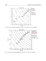
Fig. 5.32 Four diffusion-related correlations: a) diffusion process; b) thickness of diffu-
sion layer vs. concentration of diffusing element; c) diffusion coefficient vs. tempera-
ture for different concentrations of diffusing element; d) thickness of diffusion layer
vs. time for different concentrations of diffusing element.
© 1999 by CRC Press LLC