The Materials Science of Coatings and Substrates Part 2 ppsx
Bạn đang xem bản rút gọn của tài liệu. Xem và tải ngay bản đầy đủ của tài liệu tại đây (1.05 MB, 25 trang )
26
Electrodeposition
Since
many practitioners believe that
a
delay between plating and
baking could
be
important, another experiment was
run
with just two
variables, baking time and delay before baking. Bright cadmium plated
specimens were baked for
3
and
72
hours, with delays before baking of
1/4
and
24
hours
(20).
Data
in
Table
5
show diffusable hydrogen concentration
as
a
function of baking time and delay before baking. Results clearly reveal
that there was no effect on the hydrogen concentration whether or not the
baking was done as soon
as
possible after plating.
In
spite
of
these results
it is possible that elapsed time between plating and baking can be
sufficiently long enough that the migrating hydrogen reaches the critical
concentration for crack initiation.
No
amount of baking will ever repair
these cracks; the substrate will have a permanent reduction in yield strength
(21).
Table
5:
Two Variable, Two-Level Experimental Design and
Results
for
Bright Cadmium Plated
4340
Steel (a)
Baking Hydrogen Concentration
Trial Time, h The, h pNcm2 Avg.
1
3
114 0.88 1.07
1.26
2
3
24 1.08 1.05
1.02
3
72 114 0.26 0.28
0.3
1
4 72 24 0.28
0.30
0.3
1
a. From reference
20.
Background level was
0.22
pNcm2
Cd-Ti Plating
Cd-Ti plating, an approach to inhibit hydrogen embrittlement,
was
introduced in the
1960’s
(22).
This
technique utilizes a standard cadmium
cyanide solution with a sparsely soluble titanium compound plus hydrogen
peroxide. When properly operated the deposit contains from
0.1
to
0.5%
Ti.
This
process
has
been used for coating
high
strength landing gear
Hydrogen Embrittlement
27
actuation cylinders, linkage shafts and threaded rods subjected to high stress
(23).
A
noncyanide electrolyte prepared by adding a predissolved Ti
compound
to
a neutral ammoniacal cadmium solution is also available
(24).
With
this
electrolyte, fine-grained Cd-Ti deposits
containing
0.1
to
0.7%
Ti
have
been
obtained.
It
is reported that with respect
to
throwing power,
corrosion protection and hydrogen embrittlement, the noncyanide solution
is better
than
the cyanide solution. The Ti compound is stable in the
noncyanide solution,
so
the continuous filtration and frequent analysis
required with
the
Cd-Ti cyanide process are avoided. The process has
been
used since
1975
for applying protective coatings
on
high strength structural
steel, spring wire and high quality instrument steel
(24).
Figure
12,
which
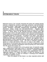
shows hydrogen permeation data for a noncyanide Cd-Ti solution, clearly
reveals the influence of Ti in inhibiting hydrogen absorption.
Figure
12:
Hydrogen penetration current vs. time in Cd plating solution
with
(1)
no
Ti,
(2)
0.067
g/l
Ti,
(3)
2.2
g/l
Ti, and
(4)
3.1
g/l
Ti. From
reference
24.
Adapted from reference
24.
Mechanical Plating
Mechanical plating is one of the coating techniques available for
minimizing hydrogen embrittlement. Also known as peen plating,
mechanical plating is
an
impact process used to apply deposits of zinc,
cadmium or tin. It has been a viable alternative to electroplating for the
application of sacrificial metal coatings on small parts such as nails, screws,
bolts, nuts, washers and stampings for over
30
years
(25).
Table
6
includes
static test data for
1075
steel heat treated to Rc
52-55
before being
electroplated with
12.5
pm
(0.5
mil) cadmium by normal procedures or by
mechanical plating. Parts coated by mechanical plating exhibited no
hydrogen embrittlement, whereas, those coated by normal plating exhibited
28
Electrodeposition
I
I
I
I
I
10
I
I
I
I
I
I
I
I
I
I
10
i
I
I
I
I
I
I
I
10
I
I
I
i
I
I
I
I
I
I
I
10
i
I
I
I
I
I
I
I
I
1
Hydrogen Embrittlement
29
various degrees
of
failure, ranging from 100% failure for small rings which
had been quenched and tempered to no failure for large rings which had
been austempered. Dynamic testing did reveal that some embrittlement
occurred as a result
of
the mechanical plating process although not
as
extensive
as
that obtained with normal plating (26).
Physical Vapor Deposition
One coating technique that eliminates the potential
of
hydrogen
embrittlement is that of physical vapor deposition (PVD), particularly ion
plating. PVD processes such as evaporation, sputtering and ion plating are
discussed in some detail in the chapter on Adhesion. Since these processes
are done in vacuum, the chance of embrittlement by hydrogen is precluded.
For production parts, precleaning consists
of
solvent cleaning followed by
mechanical cleaning with dry aluminum oxide grit
(27).
Therefore, there is
no need for costly embrittlement relief procedures nor is there the risk of
catastrophic failure due to processing. Ion plated aluminum coatings have
been used for over 20 years particularly for aircraft industry applications
(28).
This
aluminum deposit protects better than either electroplated or
vacuum deposited cadmium in acetic salt fog and most outdoor
environments. Class
I
coatings,
25
pm
(0.001 inch minimum) of ion vapor
deposited aluminum have averaged 7500 hours before the formation of red
rust in
5
percent neutral salt fog when tested under ASTM-E-117
(29).
Per mea tion
Since one of the key methods for minimizing hydrogen
embrittlement is the use of a barrier coating, the influence of various
coatings on the permeability of hydrogen
is
of importance. Thin layers of
either Pt, Cu, or electroless nickel decrease permeability of hydrogen through
iron (30). The coatings do not have to be thick or even continuous to
be
effective suggesting that a catalytic mechanism is responsible for the marked
reduction in hydrogen permeation through the iron.
Au
(31)(32), Sn and
Sn-Pb alloy coatings are also very effective permeation barriers (33)-(35).
Lead coatings are effective in preventing hydrogen cracking on a variety of
steels
in
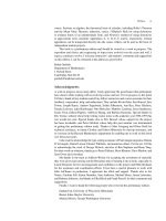
many different environments (36)-(38). Permeation data presented
in Figures 13 through
15
show that:
-
A
Pt
coating of only 0.015 pm was very effective in reducing
hydrogen permeation through iron (Figure 13).
-
Cu was noticeably more effective than Ni
in
reducing the
rate of hydrogen uptake by iron (Figure 14).
30
Electrodeposition
-
With 1017 steel, brush plating with 70Pb-30Sn noticeably
reduced the permeability (Figure
15).
An
imperfect brush
plated zinc coating
was
also quite effective
in
reducing
permeability.
Figure
13:
Effect
of
a platinum coating
(0.015
pm
thick) on the permeation
of hydrogen through Ferrovac
E
iron membranes. Charging current density
was
2
mA/cm2.
Charging solution was 0.1
N
NaOH plus
20
ppm
As
Adapted from reference 30.
Figure
14:
Effect of copper, nickel
and
electroless nickel coatings on the
permcation
of hydrogen
through
Ferrovac
E
iron membranes. Charging
current density was
2
mA/cm2. Charging solution was
0.1
N
NaOH plus
20
ppm
As
Adapted from reference 30.
Hydrogen Embrittlement
31
Figure
15:
Brush plating as a means of reducing hdyrogen uptake and
permeation in
1017
steel. Adapted from reference 33.
Extensive work
for
NASA has shown the effectiveness
of
Cu and
Au in reducing the permeability
of
hydrogen.
For
example, electrodeposited
nickel is highly susceptible to hydrogen environment embritllement (HEE)
(32)(39)(40). Both ductility and tensile scrength
of
notched specimens
E~OW
reductions up to
70
percent in 48.3 Mpa
(7000
psi) hydrogen wvlien compared
with
an
inert environment
at
room
temperature. Annealing
clt
343OC
minimizes the HEE
of
electrodeposited nickel regardless of
the
current
density used to deposit the nickel.
Anotlier
approach
to
prevent
HEE
of
electrodeposited nickel is to coat the nickel with copper
or
gold. Tensile
tests conducted to detemiine he effectiveness
of
80 pin thick copper and
25
pm
thick gold are summarized
in
Table
7.
Both coatings allowed the
electrodeposited nickel to retain its ductility
in
high pressure hydrogen (32).
Since metallurgically prepared nickel alloys are also notoriously
susceptible to hydrogen embrittlement, NASA utilizes
an
electrodeposited
copper layer
(150
um)
to protect the inner surface of a four ply nickel alloy
bellows from contacting a hydrogen atmosphere.
This
bellows is used in the
Space Shuttle engine turbine drive and discharger ducts prior to forming
(41).
32
Electrodeposition
23
m
N
8
oo-
CI
oo
m
v)
8
4
c?
oo
2
3
8
5
Hydrogen
Embrittlement
33
Electroless Copper
An
excellent application of materials science principles
is
the work
by researchers at
AT
&
T
Bell Laboratories on electroless copper. By
utilizing a variety of sophisticated analytical techniques including inert gas
fusion analysis, ion microprobe analysis,
thin
film
ductility measurements,
and scanning and transmission electron microscopy they showed that
hydrogen is responsible for the lower ductility noted in electroless copper
deposits when compared with electrodeposited copper films
(6)(42)-(49).
They attributed
this
ductility loss to hydrogen embrittlement contrary to the
common notion that physical properties of Group
IB
metals (copper, silver,
and gold) are insensitive to hydrogen
(44).
This
work should be generally
applicable to other electrodeposited and electroless films in which the
deposition process involves a simultaneous discharge of both metal and
hydrogen ions
(6).
Electroless copper deposition is used extensively in the fabrication
of printed wiring boards. Since these deposits are often subjected to
a
hot
solder bath during the printed wiring board manufacturing process, good
ductility is required to withstand thermal shock.
An
item of concern with
electroless copper deposits is their ductility which is generally much poorer
(-
3.5%)
than that of electrolytic copper
(12.6
to
16.5%) (6).
This
loss
in
film ductility for electroless copper deposits has
been
attributed to a
high
(104
am.) pressure developed because of hydrogen gas bubbles in analogy
to the pressure effect in classical hydrogen embrittlement
(6).
In
the
electroless copper deposition process, the formation of hydrogen gas is an
integral part of the overall deposition reaction:
Cu(II)
+
2HCHO +40H
+
Cu+2HCOO
+2H20
+
H,
Some of the hydrogen atoms and/or molecules can be entrapped
in
the
deposit
in
the form of interstitial atoms or gas bubbles
(48).
By contrast, in
the case of electrolytic copper deposition, hydrogen evolution can be avoided
by choosing the deposition potential below the hydrogen overpotential
to
prevent hydrogen reduction.
This
cannot
be
done with electroless copper
deposition since hydrogen reduction is
an
integral part
of
the deposition
reaction.
Table
8,
which lists the concentration ranges of impurity elements
found in an electroless copper deposit, shows that hydrogen content is
disproportionately high compared to the other elements
(46).
Some of
this
hydrogen can be removed by annealing at relatively low temperatures and
this
results in
an
improvement in ductility. Figure
16
shows the variation of
ductility and hydrogen content with annealing time at
150°C
in nitrogen.
The ductility improves with annealing time and reaches a nearly constant
34
Electrodeposition
Table
8:
Inclusions
in
Electroless
Copper Deposits (a)
Element ppm, Weight ppm, Atomic
H
30-20
1900- 1 2700
C 90-800
480-4230
0
70-250
280-990
N
20-1
10
90-500
Na
20-70
55-190
a.
These
data
are from reference 46.
Figure
16: Variation of hydrogen content and ductility
with
annealing time
at
150°C
for
an electroless copper deposit.
From
reference 46. Reprinted
with permission of The Electrochemical
SOC.
Hydrogen Embrittlement
35
level after
24
hours.
In
somewhat similar fashion, the hydrogen content
decreases initially and becomes constant after the same length
of
time.
Inspection of the hydrogen curve reveals that two
kinds
of hydrogen are
present in the deposit, "diffusable hydrogen" which escapes on annealing,
and "residual hydrogen" which is not removed by annealing
(46).
The close
correlation between the
loss
of
hydrogen and improvement in ductility shown
in Figure
16
is further demonstrated by a cathodic charging experiment
in
which
an
annealed deposit containing
no
diffusable hydrogen was made a
cathode in an acidic solution to evolve hydrogen for
an
extended period of
time, and
the
diffusable hydrogen and ductility remeasured
(46).
The results
are presented in Table
9.
This
extensive work by researchers at
AT
&
T Bell Laboratories has
led them to conclude that hydrogen inclusion introduces two sources
of
embrittlement into electroless copper. The first one
is
the classical hydrogen
embrittlement by the pressure effect and the second is the introduction
of
void regions, which promote the ductile fracture by the void coalescence
mechanism. The former embrittlement can
be
removed by annealing at
150°C
but the latter remains constant
(47).
Table
9:
Deposits (a)
Cathodic Charging Experiment With Electroless Copper
Diffusable Hydrogen
Condition Ductility
96
ppm, Atomic
As deposited
2.1
2780
After annealing
(b)
6.5
0
After charging 3.8
2360
After reannealing
(b)
6.4
0
a. These data are from reference 46. Cathodic
charging conditions:
0.05M
H,S04,
0.001
M
As,O,,
(
10mA/cm2,
15
hours)
b.
Annealing
was
done
at
15OoC for 24
hours.
36
Electrodeposition
Chemical
Milling
Chemical milling has evolved as a valuable complement to
conventional methods of metal removal. Any metal that can
be
dissolved
chemically in solution can be chemically milled. Aluminum, beryllium,
magnesium, titanium, and various steel and stainless steel alloys are among
those most commonly milled although refractory metals such
as
molybdenum, tungsten, columbium, and zirconium, can also
be
handled.
Parts
can
be
flat, preformed, or irregular, and metal can
be
removed from
selected areas or the entire surface (50).
Chemical milling of steels, stainlesses and high-temperature alloys
typically requires extremely corrosive raw-acid mixtures.
In
spite
of
the fact
that much hydrogen is generated during the process, milled parts suffer little
or
no degradation. Data in Table
10
summarize
the influence of chemical
milling on the tensile properties of various alloys.
In
most cases, no
degradation
was
noted. With
4340,
some
embrittlement was obtained with
chemically milled specimens, but properties were restored by aging at room
temperature.
Titanium alloys are chemically milled primarily
to
provide a
maximum strength-to-weight ratio. As with steels, various acids are used for
milling.therefore, hydrogen is generated (50)(59)-(61). Since titanium and
its alloys are susceptible to hydrogen embrittlement
(Figure
17) the amount
of
hydrogen picked up when these materials are chemically milled is
of
major concern
(2).
In titanium structures, hydrogen can concentrate at the
surface causing a reduction in surface sensitive properties. The most
important factors governing the amount
of
hydrogen absorbed are the
composition and metallurgical structure
of
the alloy, the composition and
temperature
of
the etching solution, the etching time, the sequence in which
the parts
fit
into the milling cycle, whether the parts are etched on one
or
both sides, and the mass of material remaining after etching. For example,
hydrogen pickup
is
much greater when specimens are milled from two sides
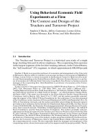
rather than just one. Figure
18
contains data for Ti-6A1-6V-2Sn. showing
that absorption is a function of the ratio of chemically milled surface to final
volume and not of the amount of metal removed by milling (59). Table 11
summarizes data on hydrogen absorption for various titanium alloys.
TESTS FOR HYDROGEN EMBRITTLEMENT
A variety
of
tests are available for assessing hydrogen embrittlement
but these will not
be
covered here. For those interested
in
these
tests,
references
63
and
64
provide a good starting point.
Hydrogen Embrittlement
37
N
a
‘0
5
m
0
w
3
X
zz
C
83:
Eia
38
Electrodeposition
Figure
17:
Tensile properties
of
TiSMn as a function
of
hydrogen content.
Adapted from reference
4.
Figure
18:
Hydrogen
absorption
vs.
depth of cut
for
chemically milled
Ti-
6A1-6V-2Sn. Adapted from reference
59.
m
m
Hydrogen Embrittlement
39
l-mw
mmm
284
999
E8E
mml-
cnmc\1
me*
www
**e
I
T
00
.A
E+
c\1
W
mmm
ml-
40
Electrodeposition
REFERENCES
1.
2.
3.
4.
5.
6.
7.
8.
9.
10.
11.
H.K. Birnbaum, "Hydrogen Embrittlement",
Encyclopedia
of
Materials Science and Engineering,
M.B. Bever, Editor, Pergamon
Press,
2240 (1986)
M.R. Louthan, Jr., "The Effect of Hydrogen
on
Metals",
Corrosion
Mechanisms,
F.
Mansfeld, Editor, Marcel Dekker Inc.,
NY
(1987)
E.A. Groshart, "Design and Finish Requirements of
High
Strength
Steels",
Metal Finishing
82.49
(March
1984)
P.
Bastien and
P.
Azou, "Effect of Hydrogen on the Deformation
and Fracture of Iron and Steel in Simple Tension",
Proceedings
of
the First World Metallurgical Congress,
ASM
(1951)
D.
Nguyen, A.W. Thompson and I.M. Bernstein, "Microstructural
Effects
on
Hydrogen Embrittlement in a High Purity
7075
Aluminum Alloy",
Acta. Metall.,
35, 2417 (1987)
S.
Nakahara and
Y.
Okinaka, "Microstructure and Ductility
of
Electroless Copper Deposits",
Acta Metall.,
31, 713 (1983)
L.J. Durney, "Hydrogen Embrittlement: Baking Prevents Breaking",
Products Finishing,
49,90
(Sept
1985)
H. Geduld,
Zinc Plating,
ASM International,
203 (1988)
H.C. Rogers, "Hydrogen Embrittlement",
Science,
159, 1057 (1968)
L.E. Probert and J.J. Rollinson, "Hydrogen Embrittlement
of
High
Tensile Steels During Chemical and Electrochemical Processing",
Electroplating
and
Metal Finishing,
14, 396
(Nov
1961)
I.M. Bernstein and A.W. Thompson, "Hydrogen Embrittlement
of
Steels",
Encyclopedia
of
Materials Science
and
Engineering,
M.B.
Bever, Editor, Pergamon Press,
2241 (1988)
Hydrogen Embrittlement
41
C.D. Beachem, "Mechanisms
of
Cracking
of
Hydrogen-Charged
(Hydrogen-Embrittled) Aerospace Materials",
Proceedings AESF
Aerospace
Symposium
(Jan
1989)
H.J. Read, "The Metallurgical Aspects
of
Hydrogen Embrittlement
in
Metal Finishing",
47fh Annual Technical Proceedings,
AES, 110
(
1960)
A.W. Grobin, "Other ASTM Committees and
IS0
Committees
Involved
in
Hydrogen Embrittlement Test Methods",
Hydrogen
Embrittlement: Prevention
and
Control,
ASTM STP 962, L.
Raymond, Editor, ASTM, Philadelphia, PA, 46 (1988)
12.
13.
14.
15.
16.
17.
18.
19.
20.
21.
C.L. Faust, "Electropolishing Carbon and
Low
Alloy Steels-Part l",
Metal Finishing,
81,47 (May 1983)
E.T. Clegg, "Hydrogen Embrittlement Coverage by
U.
S.
Government Standardization Documents",
Hydrogen Embrittlement
:
Prevention
and
Control,
ASTM STP 962, L. Raymond, Editor,
ASTM, Philadelphia, PA, 37 (1988)
A.W. Thompson, "Metallurgical Characteristics
of
Hydrogen
Embrittlement",
Plating
&
Surface Finishing,
65, 36 (Sept 1978)
A.R. Troiano, 'The Role of Hydrogen and Other Interstitials on the
Mechanical Behavior of Metals",
Trans. American Society for
Metals,
52,
54
(1960)
D.A. Berman, "Removal
of
Hydrogen From Cadmium Plated
High
Strength Steel by Baking-A Statistically Designed Study", Report
No. NADC-82238-60 (Nov 1982). Naval Air Development Center,
Warminster, PA
D.A. Berman, "The Effect
of
Baking and Stress on the Hydrogen
Content of Cadmium Plated High Strength Steels", AD-A166869
(Dec 1985). Naval Air Development Center, Warminster, PA
A.W. Grobm, Jr., "Hydrogen Embrittlement Problems",
ASTM
Standardization
News,
18,
30
(March
1990)
42
Electrodeposition
22.
23.
24.
25.
26.
27.
28.
29.
30.
31.
32.
K.
Takata, Japanese patents SHO-35 18260 (1960) and SHO-38
20703 (1963)
AMS-2419A. "Cadmium-Titanium Alloy Plating",
SOC.
of
Automotive Engineers,
Warrendale, PA (1979)
W. Sheng-Shui, C. Jing-Kun,
S.
Yuing-Mo and L. Jin-Kuel, "Cd-Ti
Electrodeposits From
a
Noncyanide Bath",
Plating
&
Surface
Finishing,
68,
62
(Dec
1981)
R.N. Holford, Jr., "Five-Year Outdoor Exposure Corrosion
Comparison",
Metal Finishing,
86, 17 (July 1988)
L.
Coch, "Plating Fasteners, Avoiding Embrittlement",
Products
Finishing,
51,
56
(May 1987)
V.L.
Holmes, D.E. Muehlberger and J.J. Reilly, "The Substitution
of IVD Aluminum for Cadmium", ESL-TR-88-75,
Engineering
&
Services Laboratory,
Tyndall
Air
Force Base, FL (Aug 1989)
E.R. Fannin and D.E. Muehlberger, "Ivadizer Applied Aluminum
Coating Improves Corrosion Performance of Aircraft", McDonnell
Aircraft Company, MCAIR 78-006 (1978)
D.E. Muehlberger, "Ion Vapor Deposition of Aluminum-More
Than
Just a Cadmium Substitute",
Plating
&
Surface Finishing,
70,
24
(Nov 1983)
S.S.
Chatterjee,
B.G.
Ateya and H.W. Pickering. "Effect
of
Electrodeposited Metals on the Permeation of Hydrogen Through
Iron Membranes",
Metallurgical Transactions
A,
9A, 389 (1978)
T-P. Pemg, M.J. Johnson and C.L Alstetter, "Hydrogen Permeation
Through Coated and Uncoated Waspalloy",
Metallurgical
Transactions
A,
19A. 1187 (1988)
W.T. Chandler, R.J. Walter, C.E. Moeller'and H.W. Carpenter,
"Effect
of
High-Pressure Hydrogen on Electrodeposited Nickel",
Plating
&
Surface Finishing
65, 63 (May 1978)
Hydrogen
Embrittlement
43
33.
34.
35.
36.
37.
38.
39.
40.
41.
42.
S.L.
Robinson, W.A. Swansiger and A.D. Andrade, "The Role of
Brush Plating
in
Future Hydrogen Storage and Transmission
Systems",
Plating
&
Surface Finishing
66, 46
(August
1979)
D.R. Begeal, "The Permeation and Diffusion of Hydrogen and
Deuterium Through Rodar, Tincoated Rodar
and
Solder-Coated
Rodar",
J.
Vac. Sci. Technol.,
12,
405
(Jan/Feb
1975)
J. Bowker and G.R. Piercy, 'The Effect
of
a Tin Barrier on
the
Permeability of Hydrogen Through Mild Steel and Ferritic Stainless
Steel",
Metallurgical Transactions A,
15A,
2093 (1984)
L.
Freiman and
V.
Titov, "The Inhibition
of
Diffusion
of
Hydrogen
Through Iron and Steel by Surface Films of Some Metals",
Zhur.
Fiz.
Khim.,
30,882 (1956)
I.
Matshushima and H.H. UhIig, "Protection of Steel From Hydrogen
Cracking by
Thin
Metallic Coatings",
J.
Electrochem.
Soc.,
113,555
(1966)
H. Tardif and H. Marquis, "Protection of Steel From Hydrogen by
Surface Coatings",
Canadian Metallurgical Quarterly,
1,153 (1962)
R.P. Jewett, R.J. Walter, W.T. Chandler and R.P. Frohmberg,
"Hydrogen Environment Embrittlement of Metals",
NASA
CR-2163,
(Mar
1963)
W.T. Chandler and R.J. Walter, "Hydrogen Embrittlement",
ASTM
STP
543,
American Society for Testing and Materials, Philadelphia,
PA,
182 (1974)
"Electroplating Offers Embrittlement Protection",
NASA
Tech Briefs,
p
140
(Spring
1979)
S.
Nakahara and
Y.
Okinaka, "Transmission Electron Microscopic
Studies of Impurities and
Gas
Bubbles Incorporated in Plated Metal
Films",
Properties
of
Electrodeposits: Their Significance
and
Measurement,
R. Sard, H. Leidheiser, Jr., and
F.
Ogburn, Editors,
The Electrochemical
Soc.,
Pennington, NJ,
(1975)
44
Electrodeposition
43.
44.
45.
46.
47.
48.
49.
50.
51.
52.
53.
Y.
Okinaka and
S.
Nakahara. "Hydrogen Embrittlement
of
Electroless Copper Deposits",
J.
Electrochem.
Soc.,
123,475 (1976)
S.
Nakahara and
Y.
Okinaka,
"On
the Effect
of
Hydrogen on
Properties of Copper",
Scripta Metall.,
19, 517 (1985)
J.E. Graebner and
Y.
Okinaka, "Molecular Hydrogen in Electroless
Copper Deposits",
J.
Appl. Physics,
60, 36 (July 1986)
Y.
Okinaka and H.K. Straschil, "The Effect of Inclusions on the
Ductility
of
Electroless Copper Deposits",
J.
Electrochem.
SOC.,
133,
2608 (1986)
S.
Nakahara, "Microscopic Mechanism
of
the Hydrogen Effect on
the Ductility
of
Electroless Copper",
Acta Metall.,
36, 1669 (1988)
S.
Nakahara and
Y.
Okinaka, "The Hydrogen Effects in Copper",
Muterials Science
and
Engineering,
A,
101, 227 (1988)
S.
Nakahara
Y.
Okinaka, and H.K. Straschil, "The Effect
of
Grain
Size on Ductility and Impurity Content
of
Electroless Copper
Deposits",
J.
Electrochem.
Soc.,
136,
1 120 (1989)
J.W. Dini, "Fundamentals
of
Chemical Milling",
American
Machinist,
128, 1 13 (July 1984)
C.
Micillo, "Advanced Chemical Milling Processes",
AFML-TR-68-237, or AD 847070 (August 1968)
R.L. Jones,
"A
New Approach to Bend Testing for the
Determination of Hydrogen Embrittlement of Sheet Materials", AD
681765 (June 1961)
Anon., "The Chemical Contouring of 3% Chromium
Mol
ybdenum-Vanadium and 5% Chromium-Mol ybdenum-Vanadium
High Strength Steel",
Bristol Aerojet England,
BR-ARC-CP-8 1 1
(March 1964)
Hydrogen
Embrittlement
45
54.
55.
56.
57.
58.
59.
60.
61.
62.
63.
64.
E.C. Kedward and P.F. Langstone, "Chemical Contouring of
18
Percent Nickel Maraging Steel",
Sheet Metal Industries,
London,
46,
473 (June 1969)
R.L. Jones and P. Bergstedt, "Compilation of Materials Research
Data, Fourth Quarterly Progress Report-Phase
1".
General
Dynumics,
AD
273065 (Dec 1961-Feb 1962)
E.
Howells, "Taper Chemical Milling
of
Rene 41 Tubes", Boeing
Co., Seattle, Wash., MDR-2-14969 (March 1962)
S.J. Ketcham, "Chemical Milling of Alloy Steels", Naval Air
Engineering Center, NAEC-AML-2418 or
AD
631952 (March 1966)
B.
Chapman and
J.
Derbyshire Jr., "Confirmation
of
the Close
Tolerance Chem-Mill Process to PH
14-8
Mo Steel for
the
Apollo
Heat Shield", North American Aviation, SDL 435 (Nov. 6, 1963)
C. Micillo and C.J. Staebler Jr., "Chemical Milling Using Cut
Maskant Etching Masks",
Photochemical Etching,
3,4 (June 1968)
CHEMICAL
MILLING,
W.T.
Harris,
Oxford Univ. Press, New
York (1976)
J.W. Dini, "Chemical Milling",
International Metallurgical Reviews,
20, 29 (1975)
R. Messler Jr. and J. Masek, "Thermal Processing, Cleaning,
Descaling and Chemical Milling
of
Ti-1 5V-3Cr-3Al-3Sn Titanium
Alloy", TMS/AIME Paper F80-15 (1979)
L.
Raymond, "Evalaution
of
Hydrogen Embrittlement",
Metals
Handbook, Ninth Edition,
Vol
13, Corrosion (1987). American
Society for Metals, Metals Park,
Ohio
Hydrogen Embrittlement: Prevention and Control,
ASTM STP 962,
L.
Raymond, Editor, American Society for Testing and Materials,
Philadelphia, PA (1988)
3
__
ADHESION
INTRODUCTION
Adhesion refers to the bond (chemical or physical) between two adjacent
materials, and is related
to
the force required
to
effect their complete
separation. Cohesive forces are involved when the separation occurs within
one
of them rather than between the two
(1).
The
ASTM
defines adhesion
as the "condition in which two surfaces are held together by either valence
forces
or
by mechanical anchoring
or
by both together"
(2).
Adhesion is a
macroscopic property which depends
on
three
factors:
1)
bonding across the
interfacial region,
2)
type of interfacial region (including amount and
distribution of intrinsic stresses) and
3)
the fracture mechanism which
results in failure
(3-5).
Equating adhesion, which is a
gross
effect, to
bonding
or
cleanliness may be very misleading. Failure
of
adhesion may
be
more related
to
fracture mechanisms than
to
bonding.
In
thin films, the
intrinsic stress may result in adhesive failure even though chemical bonding
may be high.
Also,
the interfacial morphology may lead to easy fracture
though bonding is strong. With copper,
if
an acid dip prior
to
plating is too
strong
so
that the etching results in the development of large areas with
(1
11
)
planes constituting the surface, the subsequently deposited films may
not only grow non-epitaxially, but also
lose
adhesion to
he
substrate
forming an interfacial crack because of the voids
(6).
Good adhesion is
promoted by:
1)
strong bonding across the interfacial region,
2)
low stress
gradients, either from intrinsic
or
applied stress,
3)
absence
of
easy fracture
modes, and
4)
no long term degradation modes
(3-5).
Adhesion
of
a coating
to
its substrate is critical
to
its function.
Mechanical, chemical, and metallurgical factors may contribute
to
such
46
Adhesion
47
adhesion. For a coating to be retained and to perform its function, its
adhesion
to
the substrate must tolerate mechanical stresses and elastoplastic
distortions, thermal stress, and environment
or
process fluid displacement.
Good
adhesion performance
of
a coating depends on a variety of the
attributes
of
the interface region, including its atomic bonding structure, its
elastic moduli and state of stress, its thickness, purity and fracture toughness
(7).
The durability of coatings is of prime importance in many
applications and one of the main factors that govern this durability is
adhesion. This is particularly true if the coating or substrate,
is
subject to
corrosion or
to
a humid atmosphere, as under these circumstances any
tendency for the film to peel from the substrate may well be aggravated.
When adhesion is poor, rubbing action can cause localized rupture at the
coating/subsuate interface, leading to blistering
or
even complete spalling
off of the coating.
For
example, material loss in wear tests was minimum
with Pb/Sn films deposited by ion plating which results in very good
adherence. By comparison, heavy material
loss
was obtained with Pb/Sn
films deposited by evaporation which provides considerably less adherence.
With the less adherent films deposited by evaporation, several failure
mechanisms such as plucking, peeling, film displacement, etc., were
observed
(8).
In general, adhesion can be broken down into the following
categories
(9):
1.
Interfacial adhesion:
the adhesive forces are centered around a
narrow well defined interface, with minimal atomic mixing, such
as gold on silica.
2.
Interdiffusion adhesion:
the film and substrate diffuse into one
another, over a wider interfacial region.
For
example, gold,
evaporated onto freshly etched silicon (removing the surface oxide
layer) at
50°C
produces a diffuse interface extending many atomic
layers.
3.
Intermediate layer adhesion:
in many cases the film and substrate
are separated by one or more layers of material of different
chemical composition, as in the case of films deposited on unetched
silicon whose surface is covered with several nanometers of oxide.
4.
Mechanical interlocking:
this will occur to some degree wherever
the substrate surface is not atomically flat and will account for
some degree of random fluctuation of adhesive forces.
48
Electrodeposition
TESTING
Adhesion tests can be broken down into two categories, qualitative
and quantitative. They vary from the simple scotch tape test to complicated
flyer plate tests which require precision machined specimens and a very
expensive testing facility. It is not the intent to provide a complete review
of all adhesion tests in this chapter but rather provide
some
coverage
of
those that were used
to
generate the data that is presented later.
For
those
interested in more detail, references
1
and
10-14
are recommended.
Table
1
gives a general breakdown of adhesion tests, classifying
them into qualitative and quantitative. In many cases, the qualitative tests
are
quite adequate and are certainly easier and cheaper
to
perform.
As
with
all
tests, thickness of the coating can noticeably influence the results. This
is shown in Figure
1
for the scotch tape test. Aluminum panels were not
given any special activation treatment prior
to
plating with varying
thicknesses
of
palladium
so
it
was known that adhesion would be poor. The
panel coated with only
1.25
pm
(0.05
mil) of Pd indicates fairly good
adhesion; only a small amount
of
coating was removed by the tape
test.
As
the thickness of Pd was incre,,ed increasing amounts of coating were
removed by the tape. Although not shown,
if
the coating were increased
to
around
25
pm
(1
mil) no coating would be removcd since the coating would
be
stronger than the tape even though the deposit would still be
non-adherent. Likewise, with a very thin coating, e.g., around
0.5
pm
(0.02
mil), no failure would be noticed with the scotch tape test. This strongly
shows that with a qualitative test, a variety of results can be obtained and
they can be quite misleading.
In cases where coatings are required for engineering applications,
qualitative tests are often inadequate and must be replaced with tests that
provide quantitative date.
Of
those listed in Table
1,
four
that were used to
generate data that will subsequently be discussed include tensile, shear, peel
and flyer plate
so
some details will be given for these tests.
A.
Conical
Head Tensile Test
With this test,
he
electrodeposit,
Lhe
substrate and the bond
between the two are tested in
a
tensile fashion, the bond being normal
to
the
loading direction. Flat panels are plated on both sides with thick electrode-
posit
(
e.g., around
3
mm)
and thcn conical head specimens are machined
and tested using standard tension tcsting procedures.
Figure
2
is a
schematic of conical head tcnsion specimens. More detail on
Lhis
test can
be found in references
15-17.
Adhesion
49
Table
1
-
Adheslon
Tests
Scotch
tape
Tensile
Bending Shear
Abrasion Peel
Heating Ultrasonics
Scribing Centrifuge
Grinding
Flyer
Plate
Impacting
Figure
1:
Scotch
tape
test
for
palladium platcd on aluminum.
50
Electrodeposition
Figure
2:
Conical head tensile specimen.
B.
Ring
Shear
Test
Ring shear tests are
an
effective, relatively simple method for
obtaining quantitative data on the bond between coatings and their
substrates. An added benefit with this
type
of test is that substrate material
is easier to obtain and specimens cost less to fabricate and evaluate than for
other
types
of quantitative tests
(17).
A typical test is accomplished by preparing a cylindrical rod via the
process under evaluation and then plating to a thickness
of
about
1.5
mm.
The rod is machined in a manner that removes all of the plated deposit
except for small rings
of
plating of predetermined width (generally
1.5
mm
wide, spaced approximately
2.5
cm apart). The rod is then cut between the
plated rings. These sections of the
rod
with the plated rings are tested by
forcing the rod through a hardened steel die having a hole whose diameter
is greater than that of the rod but less than that of the rod and the coating.
The bond strength can be calculated by using the load
to
cause failure and
the area
of
the coating. Figure
3
shows a ring shear test specimen and die.
References
16-18
provide more detail on ring shear testing.