Volume 13 - Corrosion Part 2 pot
Bạn đang xem bản rút gọn của tài liệu. Xem và tải ngay bản đầy đủ của tài liệu tại đây (7.7 MB, 200 trang )
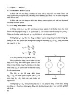
Fig. 19 Typical surface appearance of a stabilized stainless steel (X10CrNiMoTi 15 15) after a 5000-
h exposure
to flowing sodium at 700 °C (1290 °F). Cavities are formed at the grain corners; coral-
like particles of a MoFe
phase are on the grain surfaces. Courtesy of H.U. Borgstedt, Karlsruhe Nuclear Center
Fig. 20
Corrosion of Inconel alloy 706 exposed to liquid sodium for 8000 h at 700 °C (1290 °F); hot leg of
circulating system. A porous surface layer has formed with a composition of
95% Fe, 2% Cr, and <1% Ni.
The majority of the weight loss encountered can be a
ccounted for by this subsurface degradation. Total damage
depth: 45 m. (a) Light micrograph. (b) SEM of the surface of the porous layer. Source: Ref 5
Fig. 21 Corrosion of Nimonic PE 16 exposed to the same conditions described for Fig. 20. A porous coral-
like
surface layer has formed with a composition similar to that of Inconel alloy 706, but with the addition of
corrosion-
resistant FeMo particles at the coral tips. Intergranular attack beneath this layer extends to a depth of
75 m. Total damage depth: 135
m. (a) Light micrograph. (b) SEM of the surface of the porous layer.
Source: Ref 5
Fig. 22 Deposition of iron-rich crystals on Stellite 6 sheet after
5000 h in flowing sodium at 600 °C (1110
°F). Courtesy of H.U. Borgstedt, Karlsruhe Nuclear Center
Liquid lithium systems have been designed for two widely different areas: space nuclear power and fusion reactors. These
two applications draw on unique properties of this liquid metal and have led to studies with a wide range of containment
materials and operating conditions. Space power reactors require low mass; this in turn demands high-temperature
operation. Lithium, with its low melting point/high boiling point and high specific heat, is an ideal candidate heat transfer
medium. Refractory metal alloy containment is essential for these reactors, which may have design operating
temperatures as high as 1500 °C (2730 °F).
Liquid lithium in fusion reactor concepts is selected because here the neutronics allow tritium fuel to be bred from the
lithium; this is essential in order to make the economics of the reactor viable. Containment temperatures are below 700 °C
(1290 °F); therefore, iron-base alloys can be used for construction.
The effects of liquid lithium on stainless steel, nickel, and niobium containment materials are shown in Fig. 23, 24, 25,
26, 27, 28, 29, 30, 31, and 32.
Fig. 23 Corrosion of type 316 stainless steel exposed to thermally c
onvective lithium for 7488 h at the
maximum loop temperature of 600 °C (1110 °F). (a) Light micrograph of polished and etched cross section. (b)
SEM showing the top view of the porous surface. Source: Ref 6
Fig. 24 SEM micrographs of chromium mass transfer deposits found at the 460- °C (860-
°F) position in the
cold leg of a lithium/type 316 stainless steel thermal convection loop after 1700 h. Mass transfer deposits are
often a more serious result of corrosion than wall thinning. (a) Cross sec
tion of specimen on which chromium
was deposited. (b) Top view of surface. Source: Ref 7
Fig. 25
Changes in surface morphology along the isothermal hot leg of a type 304 stainless steel pumped
lithium system after 2000 h at 538 °C (1000 °F). C
omposition charges transform the exposed surface from
austenite to ferrite, containing approximately 86% Fe, 11% Cr, and 1% Ni.
(a) Inlet. (b) 7.7 m (25 ft)
downstream. Source: Ref 8
Fig. 26 Mass transfer deposits an X10CrNiMoTi 15 15 stainless steel after 1000-
h exposure in static liquid
lithium at 700 °C (1290 °F). Deposits are of the composition of the capsule steel (18Cr-8Ni).
Courtesy of H.U.
Borgstedt, Karlsruhe Nuclear Center
Fig. 27
Corrosion of a capsule wall of 18 10 CrNiMoTi stainless steel by static lithium in the presence of
zirconium foil. A porous ferritic surface layer has formed. Source: Ref 9
Fig. 28
Effects of flowing lithium on the inside surface of a type 316 stainless steel tubing. (a) Pickled surface
before exposure. Composition: 65.8 Fe-18.0Cr-9.2Ni-3.3Mn-2.6Mo-
0.9Si. (b) After exposure in flowing lithium
(0.3 m/s, or 1 ft/s) for 1250 h at 490 °C (915 °F). Composition: 88.6Fe-7.5Cr-1.7Ni-
0.6Mn. (c) After exposure
to flowing lithium (1.3 m/s, or 4.3 ft/s) for 3400 h at 440 °C (825 °F). Taper section used to magnify damaged
surface zone in metallographic mount. Courtesy of D.G. Bauer and W.E. Stewart, University of Wisconsin.
Fig. 29 Corrosion of nickel in static lithium after exposure for 300 h at 700 °C (1290 °F).
(a) Light micrograph.
(b) SEM micrograph. Source: Ref 10
Fig. 30
Light micrograph of the polished and etched cross section of niobium containing 1500 wt ppm of
oxygen showing the transcrystalline and grain boundary penetration that o
ccurred after exposure to isothermal
lithium for 100 h at 500 °C (930 °F). Source: Ref 11
Fig. 31
Intergranular attack of unalloyed niobium exposed to lithium at 1000 °C (1830 °F) for 2 h. Light
micrograph. Etched with 25% HF, 12.5 HNO
3
, 12.5% H
2
SO
4
in water. Source: Ref 12
Fig. 32
Iron crystals found in a plugged region of a failed pump channel of a lithium processing test loop.
Multifaceted platelike crystals are
0.4 mm (0.015 in.) across. Composition: 86 to 93% Fe, 7 to 14% Ni, 0 to
1% Mn. (a) SEM. 70×. (b) Iron x-ray scan. 70×. (c) SEM. 90×. Source: Ref 13
Liquid mercury, potassium, and cesium have also been used for space and terrestrial applications. In some cases, these
have involved two-phase systems in which the corrosion consideration became significantly altered. Lead, lead-bismuth,
and lead-lithium alloys (Fig. 33) have received attention for topping cycle heat extraction systems, heat exchangers,
reactor coolants, and, more recently, fusion reactor designs.
Fig. 33
Light micrograph of the polished cross section of a type 316 stainless steel exposed to thermally
convective Pb-17at.% Li at 500 °C (930 °F) for 2472 h. Source: Ref 14
There are many other combinations of containment and liquid metals that have contributed to the knowledge of corrosion
behavior; some have proved to be benign, while others have resulted in short-term catastrophic failures. In the discussion
"Safety Considerations" in this section, some brief notes are given regarding safety precautions for handling liquid metals,
operating circulating systems, dealing with fire and spillage, and cleaning contaminated components.
Forms of Liquid-Metal Corrosion
The forms in which liquid-metal corrosion are manifested can be divided into the following categories.
• Dissolution from a surface by (1) direct dissolution, (2) surface reaction, involving solid-
metal atom(s),
the liquid metal, and an impurity element present in the liquid metal, or (3) intergranular attack
• Impurity and interstitial reactions
• Alloying
• Compound reduction
All the variables present in the system play a part in the form and rate of corrosion that is established. There are ten key
factors that have a major influence on the corrosion of metals and alloys by liquid-metal or liquid-vapor metal coolants.
These are:
• Composition, impurity content, and stress conditionof the metal or alloy
• Exposure temperature and temperature range
• Impurity content of the liquid metal
• Circulating or static inventory
• Heating/cooling conditions
• Single or two-phase coolant
• Liquid-metal velocity
• Presence/control of corrosion inhibition elements
• Exposure time
• Monometallic or multialloy system components.
These factors have a varied influence, depending on the combination of containment material and liquid metal or liquid-
metal alloy. In most cases, the initial period of exposure (of the order of 100 to 1000 h, depending on temperature and
liquid metal involved), is a time of rapid corrosion that eventually reaches a much slower steady-state condition as factors
related to solubility and activity differences in the system approach a dynamic equilibrium. In some systems, this
eventually leads to the development of a similar composition on all exposed corroding surfaces. High-nickel alloys and
stainless steel exposed together in the high-temperature region of a sodium system will, for example, all move toward a
composition that is more than 95% Fe.
Compatibility of a liquid metal and its containment varies widely, as is illustrated in Fig. 17, 18, 19, 20, 21, 22, 23, 24, 25,
26, 27, 28, 29, 30, 31, 32, and 33. For a pure metal, surface attrition may proceed in an orderly, planar fashion, being
controlled by either dissolution or a surface reaction. For a multicomponent alloy, selective loss of certain elements may
lead to a phase transformation. For example, loss of nickel from austenitic stainless steel exposed to sodium may result in
the formation of a ferritic surface layer (Fig. 17, 18a, 25, and 27). In high-nickel alloys, the planar nature of the corroding
surface may be lost altogether, and a porous, spongelike layer may develop (Fig. 20 and 21). A more insidious situation
can produce intergranular attack; liquid lithium, for example, will penetrate deep into refractory metals if precautions are
not taken to ensure that the impurity element oxygen is in an oxide form more stable than Li
2
O or LiO solutions, and is
not left free in solid solution. Figure 31 illustrates intergranular attack in niobium.
Three factors surface attrition, depth of depleted zone (for an alloy), and the presence of intergranular attack should be
evaluated collectively in any liquid-metal system. This evaluation will lead to an assessment of total damage, which may
be presented either as a rate or as a cumulative allowance that must be made for the exposure of a given material over a
given time. A large body of literature exists in which rate relationships for numerous liquid metal/containment
combinations have been established. The more basic principles of liquid-metal corrosion are outlined in the article
"Fundamentals of High-Temperature Corrosion in Liquid Metals" in this Volume and in the Selected References that
follow this article.
One vitally important aspect of liquid-metal corrosion that is often overlooked is deposition. Corrosion itself is very often
not a factor of major concern because surface recession rates in regions of maximum attack are often of the order of
microns per year. The formation of compounds in the circulating liquid metal and the accumulation of deposits in
localized regions where there is a drop in temperature, a change in flow rate or flow direction, or an induced change in
surface roughness can, however, be very serious. If these deposits do not succeed in restricting flow channels completely,
their nature is often such that they are only loosely adherent to deposition surfaces and may be dislodged by vibrations or
thermal shock in the system, thus creating a major coolant flow restriction in a high-temperature region. Most deposits
have a very low packing density; therefore, deposit growth can proceed at a rate that outstrips corrosion by several orders
of magnitude. Examples of loosely adherent deposits are shown in Fig. 18(b), 22, 24, and 26. Figure 32 shows iron
crystals that restricted flow in a pump channel of a lithium processing test loop.
Liquid-metal corrosion, as in other forms of corrosion, involves an appreciation for the source of corrosion in any system
and an understanding of how potential sinks will operate on the corrosion burden, particularly if the liquid metal is not
static but is circulated in a heat-transfer system either by pumping or by thermal convection.
Safety Considerations
The extensive work with the alkali and liquid metals has shown that such materials can be safely handled and used,
provided certain precautions are needed. The requirements for the safe use of liquid metals are in essence those of good
industrial or laboratory practice, involving protection from contamination, chemical reactions, exposure to toxic or
irritating substances, and protection from high temperatures. More specific information and details on safe operation and
handling are available in Ref 15 and 16 and in the Materials Safety Data sheets issued by the Manufacturing Chemists'
Association.
Chemical Reactivity. All the liquid metals react with oxygen and moisture to some degree; with the alkali metals, the
reaction is vigorous enough to be potentially hazardous, particularly with potassium, rubidium, and cesium. Use of inert
gas covers and the exclusion of moisture are the best defenses. Even with the nonalkali metals where the reactions with
water are slow, water, such as that found on equipment that is not completely dry, must not be brought in contact with
liquid metals because of the danger of a steam explosion that can scatter liquid metal over a considerable area, damaging
equipment and inflicting severe burns on unprotected workers. It goes without saying that workers in the vicinity of
liquid-metal systems should wear appropriate protective clothing (Ref 15).
Potassium, rubidium, and cesium form higher oxides than the monoxide when exposed to air; these compounds are
powerful oxidizing agents, often shock sensitive, and definitely hazardous in the proximity of organic materials. They will
form at room temperature in contact with the solid metals. The practical application of this information is the need for
extreme caution when handling the metals or compounds of the heavier alkali metals, particularly when they have been
stored for extended periods under less-than-ideal conditions, or when cleaning spills or fire residues. It is noted that the
sodium-potassium eutectic alloy (NaK) will form potassium super-oxide when exposed to air or oxygen. Because NaK is
liquid at normal room temperature, small leaks at low temperature do not necessarily freeze and self-seal.
Circulating Systems. It is usually convenient to provide a closed circulating system, or loop, in which to perform
liquid-metal corrosion experiments. Reference 16 describes a simple system; the principles involved are the same for even
very complex specialized devices. The loop will provide the means for circulation of the liquid metal; it will contain
devices for on-line purification (if needed), while the inert cover gas will protect against chemical contamination.
Insulation and an enclosure will protect against high temperatures and the spread of reaction products in case of a
containment breach. Such systems provide a safe, convenient environment for handling liquid metals. Detailed operating
procedures, involving common-sense principles such as maintaining the inert cover gas at all times and melting frozen
metals by directionally heating away from a free surface, must be worked out for each system. The tens of millions of
hours of safe operation of such systems, ranging from 1-L capacity test rigs to 4000-MW (thermal) nuclear reactors,
validate the concept. References 17 and 18 describe many such test systems and the experiments performed in them.
Recovery From Spills and Accidents. It must be remembered that spills of the nonalkali metals, even though the
chemical reactivity hazard may not be great, must be handled with care because of the toxic nature of many of the metals
and their vapors. Leaks and spills of the alkali metals, particularly when some of the leaked material has burned, present a
special hazard because the spilled material often contains finely divided unreacted metal mixed with combustion
products. Such mixtures can react vigorously with moist air, water, and alcohol. The products of the heavier alkali metals
are the most reactive in this respect, but mixtures containing sodium and lithium are certainly not immune to violent
reactions if carelessly handled. Cleanup of these residues must be approached with extreme care.
Removal of Residual Metals From Corrosion Specimens. Nonalkali metals can often be removed from
corrosion specimens by draining, forming an amalgam or solution with an alkali metal, and then removing the mixture by
a technique discussed below. Alkali metals can be removed from specimens by reaction with water or alcohols; the most
vigorous reaction is with water, and the rate decreases as one progresses to heavier weight alcohols. The reaction becomes
more vigorous with increasing atomic weight of the alkali metals. Cesium/water reactions are definitely explosive. Use of
ethanol and methanol is generally safe for sodium reaction, but one must remember the flammability hazard with alcohol
vapors. The glycol ethers, such as butyl cellosolve, can also be used; they react more slowly than water, present less of a
fire hazard than ethanol or methanol, but have toxic liquid and vapors. The water, alcohol, and glycol ether reactions all
generate hydrogen; adequate ventilation must be provided to prevent the buildup of the hydrogen and the attendant danger
of an explosion.
Anhydrous liquid ammonia forms a true solution with the alkali metals and can be used to remove adherent alkali metals
from corrosion specimens. Precautions against the hazards of liquid ammonia must be taken; the alkali metal in solution
with ammonia is then usually reacted with water or alcohol before the ammonia mixture is discarded. The conditions must
be maintained truly anhydrous in order to avoid hydrogen generation and contamination of the samples. Hydrogen can
become implanted in refractory metal samples and embrittle them even at subzero temperatures. If the proper equipment
is available, evaporation of the residual metal from the surface can be done with excellent results.
Removal of alkali materials from pipework, if hydrogen generation is not a problem, can be accomplished with alcohol or
gycol ether reaction, optionally followed by water rinsing to wash away the reaction products. It must be remembered that
these reagents react very slowly, if at all, with oxides of the alkali metals. Another successful method in use is reaction
with water vapor/inert gas (argon or nitrogen) mixtures, or water spray in an inert carrier gas, followed by water rinsing.
Evaporation has also been successfully used and could be considered where hydrogen generation is not permitted.
Ammonia-base systems have also been used for refractory metal pipework where hydrogen generation was prohibited.
References 16, 17, and 18 contain more detailed information.
Fire Protection and First Aid. Firefighting and medical treatment should, of course, be left to the professionals.
There are, however, several factors to keep in mind. An alkali metal fire does not expand, as does, for example, a
petroleum fire. It does produce vast quantities of caustic smoke that react with moisture in or on the body, and this
produces severe burns. The smoke must be avoided unless respiratory protection and protective clothing are worn.
Lithium presents a special hazard because of the toxic nature of some of its compounds and because it reacts with
nitrogen. The combustion products of a lithium fire contain nitride and acetylide, which react with water to form
ammonia and acetylene, respectively.
The only way to extinguish liquid-metal firs reliably is to smother them; various drying agents, such as sodium carbonate,
sodium chloride, powdered dry graphite, or carbon microspheres, are effective. The sodium compounds should not be
used on a lithium fire because of the chemical displacement reaction producing sodium metal that takes place. Instead, the
graphite products should be used for extinguishment. It should be noted that few substances float on lithium; most tend to
sink. Reference 19, however, describes the use of a ternary eutectic BaCl-NaCl-KCl salt for effective lithium fire
extinguishment.
Inert gas blanketing is also effective for extinguishing fires; argon is preferred to nitrogen because of its higher density.
Very effective fire suppression can be achieved by using inert gas blanketing in combination with a catch pan having a
perforated floor to let the escaping liquid metal run to a second argon-blanketed chamber underneath the first. Of course,
the hazards of oxygen-deficient atmospheres must be recognized and controlled when using inert gas flooding as fire
suppression. Reference 20 provides more information about fire suppression in the alkali metals.
Emergency first aid treatment should concentrate on removing the victim from danger (for example, out of the smoke
generated by a fire) and then removing the metal or compounds from skin and eyes. Running water is the most effective
treatment because the cooling and flushing effect overcomes any hazard from reaction of a small amount of metal on the
skin or clothing. Safety showers and eyewash fountains should be readily available to workers involved with liquid
metals; they should not be eliminated because of the presence of the alkali metals. More than one person has been spared
serious injury because a safety shower was available to wash away a sodium spill.
High-Temperature Corrosion
Ian G. Wright, Battelle Columbus Division
When metal is exposed to an oxidizing gas at elevated temperature, corrosion can occur by direct reaction with the gas,
without the need for the presence of a liquid electrolyte. This type of corrosion is referred to as tarnishing, high-
temperature oxidation, or scaling. The rate of attack increases substantially with temperature. The surface film typically
thickens as a result of reaction at the scale/gas or metal/scale interface due to cation or anion transport through the scale,
which behaves as a solid electrolyte. For continuous, nonporous scales, ionic transport through the scale is the rate-
controlling process. The thermodynamic stability, the ionic defect structure, and certain morphological features of the
scale formed are key factors in determining the resistance of an alloy to a specific environment.
Initial film growth is usually very rapid. If the scale is a nonporous solid and completely covers the metal surface, the
reaction rate will decrease when the thickness reaches a few thousand angstroms as the transport of reactive species
through the film becomes rate controlling. The subsequent corrosion rate depends on the details of this transport
mechanism, which may be due to electrical potential or concentration gradients or to migration along preferential paths,
and so may correspond to any of several rate laws, as shown in Fig. 34. Where a diffusion process is rate controlling, the
kinetics usually follow a parabolic rate law, in which the rate progressively decreases with time. Figure 35(a) illustrates
the compact, continuous protective scale of essentially chromium oxide (Cr
2
O
3
) formed on Alloy 800. If the scale is
porous (or is formed as a vapor species) or does not completely cover the metal surface, a linear rate is usually
experienced.
Fig. 34 Forms of kinetic curves that represent various thermal degradation process
Fig. 35 Protective and nonprotective scales formed on Alloy 800. (a) Cr
2
O
3
-base prote
ctive oxide scale formed
in sulfur-free oxidizing gas. (b) Sulfide-
oxide scale formed in reducing conditions containing hydrogen sulfide.
Courtesy of I.G. Wright, Battelle Columbus Division
The latter circumstance can be assessed from the Pilling-Bedworth ratio, which is the ratio of the volumes of oxide
produced to the metal consumed by oxidation; values of 1.0 or greater result in complete surface coverage by oxide and,
usually, protective behavior. This is not a complete nor foolproof measure for assessing the likelihood of protective
scaling behavior. At high temperatures, the growth of nominally protective oxides may be sufficiently rapid that the
compressive stresses resulting from a Pilling-Bedworth ratio greater than 1 become sufficiently great that the scale (or
alloy) deforms and possibly spalls as a relief mechanism; in some cases, the protection offered by such scales may be low
at this point, as shown in Fig. 36.
Fig. 36 Cr
2
O
3
scale formed on pure chromium at 1100 °C (2012 °F). A Pilling-
Bedworth ratio of 2.0 results in
high compressive stress in the scale, which is relieved by buckling and spalling.
Courtesy of I.G. Wright,
Battelle Columbus Division.
The desired characteristics for a protective oxide scale include the following:
• Hi
gh thermodynamic stability (highly negative Gibbs free energy of formation) so that it forms preferentially to
other possible reaction products
• Low vapor pressure so that the oxide forms as a solid and does not evaporate into the atmosphere
• Pilling-Bedworth ratio greater than 1.0 so that the oxide completely covers the metal surface
•
Low coefficient of diffusion of reactant species (metal cations, and corrodent anions) so that the scale has a slow
growth rate
• High melting temperature
• Good adherence to t
he metal substrate, which usually involves a coefficient of thermal expansion close to that of
the metal, and sufficient high-temperature plasticity to resist fracture from differential thermal expansion stresses
High-temperature scales are usually thought of as oxides, but may also be sulfides, possibly carbides, or mixtures of these
species. Oxides and sulfides are nonstoichiometric compounds and semiconductors. There are essentially two types of
semiconductors: p-type (or positive carrier) which may have vacancies in its metal lattice, or an excess of anions
contained interstitially and n-type (or negative carrier) which may have an excess of metal ions contained interstitially,
or vacant anion lattice sites. For diffusion-controlled scaling, the rate of scale growth can be altered by modification of the
concentration of the particular defects involved. For example, p-type oxides exhibit increased cationic transport rates
(increased oxidation rates) at increased oxygen pressures, while transport in n-type oxides is essentially independent of
oxygen pressure. Both types of oxide can be doped by the addition of specific ions to the oxide lattice. For p-type metal
deficit oxides, for example, the addition of cations of higher valence than the native cations results in an increase in the
number of cation vacancies and therefore an increase in the oxidation rate, while lower-valence cation additions have the
opposite effect.
Sulfides typically exhibit an intrinsically greater rate of transport of anions and cations than the oxides of the same metal
and so provide scales that are significantly less protective than oxides. Detailed information on the kinetics of high-
temperature corrosion in gases and the thermodynamic stability of oxide/sulfide scales can be found in the article
"Fundamentals of Corrosion in Gases" in this Volume.
High-Temperature Oxidation
Alloys intended for high-temperature applications are designed to have the capability of forming protective oxide scales.
Alternatively, where the alloy has ultrahigh-temperature strength capabilities (which is usually synonymous with reduced
levels of protective scale forming elements), it must be protected by a specially designed coating. Oxides that effectively
meet the criteria for protective scales listed above and can be formed on practical alloys are limited to Cr
2
O
3
, alumina
(Al
2
O
3
), and possibly silicon dioxide (SiO
2
). In the pure state, Al
2
O
3
exhibits the slowest transport rates for metal and
oxygen ions and so should provide the best oxidation resistance.
Alloying requirements for the production of specific oxide scales have been translated into minimum levels of the scale-
forming elements, or combinations of elements, depending on the base alloy composition and the intended service
temperature. Figure 37 schematically represents the oxidation rate of iron-chromium alloys (1000 °C, or 1832 °F, in 0.13
atm oxygen) and depicts the types of oxide scale associated with various alloy types. Figure 38 illustrates the morphology
of a semiprotective scale formed on a cobalt-chromium alloy. Alloys based on these minimum specifications will form
the desired protective oxide upon initial exposure, but because of the accompanying deletion of the scale forming
element, they will probably be unable to re-form the protective layer in the event of loss or failure of the initial scale.
Fig. 37
Schematic of the variation with alloy chromium content of the oxidation rate and oxide scale structure
(based on isothermal studies at 1000 °C, or 1832 °F, in 0.13 atm oxygen)
Fig. 38 Multilayer oxide scale formed on Co-10Cr alloy at 1100 °C (2012 °F). Out
er layer is CoO; inner
(mottled gray) layer is CoO containing dissolved chromium and particles of Co-
Cr spinel. The chromium level in
this alloy is insufficient to form a fully protective Cr
2
O
3
scale.
Courtesy of I.G. Wright, Battelle Columbus
Division
A useful concept in assessing the potential high-temperature oxidation behavior of an alloy is that of the reservoir of
scale-forming element contained by the alloy in excess of the minimum level (around 20 wt% for iron-chromium alloy at
1000 °C, or 1832 °F, according to Fig. 37). The more likely the service conditions are to cause repeated loss of the
protective oxide scale, the greater the reservoir of scale-forming element required in the alloy for continued protection.
Extreme cases of this concept result in chromizing or aluminizing to enrich the surface regions of the alloy or in the
provision of an external coating rich in the scale-forming elements.
The breakdown of protective scales based on Cr
2
O
3
or Al
2
O
3
appears, in the majority of cases, to originate through
mechanical means. The most common is spallation as a result of thermal cycling, or loss through impact or abrasion.
Typical scale structures on an Fe-18Cr alloy after thermal cycling are shown in Fig. 39. Cases in which the scales have
been destroyed chemically are usually related to reactions occurring beneath deposits, especially where these consist of
molten species. An additional mode of degradation of protective Cr
2
O
3
scale is through oxidation to the volatile
chromium trioxide (CrO
3
), which becomes prevalent above about 1010 °C (1850 °F) and is greatly accelerated by high
gas flow rates.
Fig. 39 Topography (a) and cross section (b) of oxide scale formed on Fe-
18Cr alloy at 1100 °C (2012 °F). The
bright areas on the alloy surface (a) are areas from which scale has spalled. The buckled scale and locally
thickened areas (b) are iron-rich oxide. The thin scale layer adjacent to the alloy is Cr
2
O
3
, which controls the
oxidation rate. Courtesy of I.G. Wright, Battelle Columbus Division
Because these protective oxide scales will form wherever the alloy surface is exposed to the ambient environment, they
will form at all surface discontinuities; therefore, the possibility exists that notches of oxide will form at occluded angles
in the surface, which may eventually serve to initiate or propagate cracks under thermal cycling conditions. The
ramifications of stress-assisted oxidation (and of oxidation assisting the applied stress) in the production of failure
conditions are not very well understood, but constitute important considerations in practical failure analysis.
Sulfidation
When the sulfur activity (partial pressure, concentration) of the gaseous environment is sufficiently high, sulfide phases,
instead of oxide phases, can be formed. The mechanisms of sulfide formation in gaseous environments and beneath
molten-salt deposits have been determined in recent years. In the majority of environments encountered in practice by
oxidation-resistant alloys, Al
2
O
3
or Cr
2
O
3
should form in preference to any sulfides, and destructive sulfidation attack
occurs mainly at sites where the protective oxide has broken down. The role of sulfur, once it has entered the alloy,
appears to be to tie up the chromium and aluminum as sulfides, effectively redistributing the protective scale-forming
elements near the alloy surface and thus interfering with the process of formation or re-formation of the protective scale.
If sufficient sulfur enters the alloy so that all immediately available chromium or aluminum is converted to sulfides, then
the less stable sulfides of the base metal may form because of morphological and kinetic reasons. It is these base metal
sulfides that are often responsible for the observed accelerated attack, because they grow much faster than the oxides or
sulfides of chromium or aluminum; in addition, they have relatively low melting points, so that molten slag phases are
often possible. Fig. 35 compares a protective (oxide) scale and a nonprotective (sulfide) scale formed on Alloy 800.
Sulfur can transport across continuous protective scales of Al
2
O
3
and Cr
2
O
3
under certain conditions, with the result that
discrete sulfide precipitates can be observed immediately beneath the scales on alloys that are behaving in a protective
manner. For reasons indicated above, as long as the amount of sulfur present as sulfides is small, there is little danger of
accelerated attack. However, once sulfides have formed in the alloy, there is a tendency for the sulfide phases to be
preferentially oxidized by the encroaching reaction front and for the sulfur to be displaced inward, forming new sulfides
deeper in the alloy, often in grain boundaries or at the sites of other chromium- or aluminum-rich phases, such as
carbides. In this way, finger-like protrusions of oxide/sulfide can be formed from the alloy surface inward, which may act
to localize stress or otherwise reduce the load-bearing section. Such attack of an austenitic stainless steel experienced in a
coal gasifier product gas is shown in Fig. 40. The sulfidation behavior of Alloy 800 at temperatures and oxygen and sulfur
potentials representative of coal gasification processes is illustrated in Fig. 41, 42, and 43.
Fig. 40 Example of high-temperature sulfidation attack in a type 310 heat-exchanger tube after
100 h at 705
°C (1300 °F) in coal gasifier product gas.
Fig. 41 Alloy 800 test coupons with a 0.254-mm (0.01-
in.) diam grain size exposed to a coal gasifier
environment for 100 h. (a) and (c) Tested at 650 °C (1200 °F) and oxygen and sulfur partial pressures of 3 ×
10
-24
atm and 1 × 10
-8
atm, respectively. (b) and (d) Tested at 650 °C (1200 °F) and pO
2
= 3 × 10
-24
atm and
pS
2
= 1 × 10
-9
atm. SEM micrographs show sulfide scale (c) and an external sulfide formation (d). (a) and (b)
2×. Courtesy of G.R. Smolik and D.V. Miley, E.G. & G. Idaho, Inc.
Fig. 42 Sulfidation attack of Alloy 800 test coupons exposed to a coal gasifier environment (pO
2
= 3 × 10
-20
atm and pS
2
= 1 × 10
-7
atm) at 870 °C (1600 °F) for 100 h. (a) and (b) Macrograph and micrograph,
respectively, of a test coupon with a 0.254-mm (0.01-in.) diam grain size. (c) Mic
rograph showing external
sulfides, sulfide scale, and intergranular sulfidation of a test coupon with a 0.022- to 0.032-mm (0.0008-
to
0.0013-in.) diam grain size. (a) 1.5×. Courtesy of G.R. Smolik and D.V. Miley, E.G. & G. Idaho, Inc.
Fig. 43 Macrograph (a) of an Alloy 800 test coupon with a 0.254-mm (0.01-
in.) diam grain size exposed to a
coal gasifier environment (pO
2
= 3 × 10
-19
atm and pS
2
= 1 × 10
-7
atm) at 870 °C (1600 °F) for 100 h.
1.5×.
Micrographs (b) and (c) show cross sections through the Cr
2
O
3
layer and disrupted oxide region having external
sulfides. Courtesy of G.R. Smolik and D.V. Miley, E.G. & G. Idaho, Inc.
Carburization
As in the case of sulfide penetration, carburization of high-temperature alloys is thermodynamically unlikely except at
very low oxygen partial pressures, because the protective oxides of chromium and aluminum are generally more likely to
form than the carbides. However, carburization can occur kinetically in many carbon-containing environments. Carbon
transport across continuous nonporous scales of Al
2
O
3
or Cr
2
O
3
is very slow, and alloy pretreatments likely to promote
such scales, such as initially smooth surfaces or preoxidation, have generally been found to be effective in decreasing
carburization attack. In practice, the scales formed on high-temperature alloys often consist of multiple layers of oxides
resulting from localized bursts of oxide formation in areas where the original scale was broken or lost. The protection is
derived from the innermost layer, which is usually richest in chromium or aluminum. Concentration of gaseous species
such as carbon monoxide in the outer porous oxide layers appears to be one means by which sufficiently high carbon
activities can be generated at the alloy surface for carburization to occur in otherwise oxidizing environments. The
creation of localized microenvironments is also possible under deposits that create stagnant conditions not permeable by
the ambient gas.
Once inside the alloy, the detrimental effects of the carbon depend on the location, composition, and morphology of the
carbide formed. Austenitic steels should carburize more readily than ferritic steels because of the high solubility of carbon
in austenite. Iron-chromium alloys containing less than about 13% Cr contain various amounts of austenite, depending on
temperature, and should be susceptible to carburization, while alloys with 13 to 20% Cr will form austenite as a result of
absorption of small amounts of carbon. Iron-chromium alloys containing more than 20% Cr can absorb considerable
amounts of carbon before austenite forms, becoming principally (CrFe)
23
C
6
and ferrite. An example of rapid high-
temperature carburization attack of an austenitic stainless steel is shown in Fig. 44.
Fig. 44 Example of high-temperature carburization attack pitting in type 310 reactor wall after 4000-
h
exposure to coal gasification product gas. The pits were formed dur
ing operation under conditions of high
carbon activity in the gas. (a) Overall view of pitting. (b) Section through a pit.
Courtesy of I.G. Wright, Battelle
Columbus Division
Minor alloying elements can exert an influence on the susceptibility to carburization of various alloys. In particular,
silicon, niobium, tungsten, titanium, and the rare earths have been noted as promoting resistance to carburization.
Experience with aluminum and manganese has been varied, while lead, molybdenum, cobalt, zirconium, and boron are
considered detrimental.
Other Forms of High-Temperature Corrosion
Hydrogen Effects. In hydrogen at elevated temperatures and pressures, there is increasing availability of atomic
hydrogen that can easily penetrate metal structures and react internally with reducible species. An example is the attack
experienced by carbon steel, in which atomic hydrogen reacts with iron carbide to form methane, which then leads to
fissuring of the steel. Alloy steels with stable carbides, such as chromium carbides, are less susceptible to this form of
attack. For example, 2.25 Cr-1Mo suffers some decarburization in high-temperature high-pressure hydrogen, but is less
likely to fissure than carbon steel. The susceptibility of steels to attack by hydrogen can be judged from the Nelson
Curves, which indicate the regions of temperature and pressure in which a variety of steels will suffer attack. Nelson
curves and examples of high-temperature hydrogen attack of carbon and alloy steels are illustrated and discussed in the
article "Corrosion in Petroleum Refining and Petrochemical Operations" in this Volume.
A further example of hydrogen attack is copper containing small amounts of cuprous oxide. This oxide reacts to form
steam within the alloy, resulting in significant void formation.
Hot Corrosion. The term hot corrosion is generally used to describe a form of accelerated attack experienced by the hot
gas path components of gas turbine engines. Two forms of hot corrosion can be distinguished; most of the corrosion
encountered in turbines burning liquid fuels can be described as Type I hot corrosion, which occurs primarily in the metal
temperature range of 850 to 950 °C (1550 to 1750 °F). This is a sulfidation-based attack on the hot gas path parts
involving the formation of condensed salts, which are often molten at the turbine operating temperature. The major
components of such salts are sodium sulfate (Na
2
SO
4
) and/or potassium sulfate (K
2
SO
4
), apparently formed in the
combustion process from sulfur from the fuel and sodium from the fuel or the ingested air. Because potassium salts act
very similarly to sodium salts, alkali specifications for fuel or air are usually taken to the sum total of sodium plus
potassium. An example of the corrosion morphology typical of Type I hot corrosion is shown in Fig. 45.
Fig. 45 Ni-20Cr-2ThO
2
after simulated Type I hot corrosion exposure (coated with Na
2
SO
4
and oxidized in air at
1000 °C, or 1832 °F). A, nickel-rich scale; B, Cr
2
O
3
subscale; C, chromium sulfides.
Courtesy of I.G. Wright,
Battelle Columbus Division
Very small amounts of sulfur and sodium or potassium in the fuel and air can produce sufficient Na
2
SO
4
in the turbine to
cause extensive corrosion problems because of the concentrating effect of turbine pressure ratio. For example, a threshold
level has been suggested for sodium in air of 0.008 ppm by weight below which hot corrosion will not occur. Type I hot
corrosion, therefore, is possible even when premium fuels are used. Other fuel (or air) impurities, such as vanadium,
phosphorous, lead, and chlorides, may combine with Na
2
SO
4
to form mixed salts having reduced melting temperature and
thus broaden the range of conditions over which this form of attack can occur. Also, agents such as unburned carbon can
promote deleterious interactions in the salt deposits.
Research over the past 15 years has led to greater definition of the relationships among temperature, pressure, salt
concentration, and salt vapor-liquid equilibria so that the location and rate of salt deposition in an engine can be predicted.
Additionally, it has been demonstrated that a high chromium content is required in an alloy for good resistance to Type I
hot corrosion. The trend to lower chromium levels with increasing alloy strength has therefore rendered most superalloys
inherently susceptible to this type of corrosion. The effects of other alloying additions, such as tungsten, molybdenum,
and tantalum, have been documented, and their effects on rendering an alloy more or less susceptible to Type I hot
corrosion are known and mostly understood.
Although various attempts have been made to develop figures of merit to compare superalloys, these have not been
universally accepted. Nonetheless, the near standardization of such alloys as Alloy 738 and Alloy 939 for first-stage
blades/buckets, and FSX-414 for first stage vanes/nozzles, implies that these are the accepted best compromises between
high-temperature strength and hot corrosion resistance. It has also been possible to devise coatings with alloying levels
adjusted to resist this form of hot corrosion. The use of such coatings is essential for the protection of most modern
superalloys intended for duty as first-stage blades or buckets.
Type II, or low-temperature hot corrosion, occurs in the metal temperature range of 650 to 700 °C (1200 to 1400 °F), well
below the melting temperature of Na
2
SO
4
, which is 884 °C (1623 °F). This form of corrosion produces characteristic
pitting, which results from the formation of low-melting mixtures of essentially Na
2
SO
4
and cobalt sulfate (CoSO
4
), a
corrosion product resulting from the reaction of the blade/bucket surface with sulfur trioxide (SO
3
) in the combustion gas.
The melting point of the Na
2
SO
4-
CoSO
4
eutectic is 540 °C (1004 °F). Unlike Type I hot corrosion, a partial pressure of
SO
3
in the gas is critical for the reactions to occur. Knowledge of the SO
3
partial pressure-temperature relationships inside
a turbine allows some prediction of where Type II hot corrosion can occur. Cobalt-free nickel-base alloys (and coatings)
may be more resistant to Type II hot corrosion than cobalt-base alloys; it has also been observed that resistance to Type II
hot corrosion increases with the chromium content of the alloy or coating.
References
1. C.P. Larrabee, Corrosion Resistance of High Strength Low-
Alloy Steels as Influenced by Composition and
Environment, Corrosion, Vol 9 (No. 8), 1953, p 259-271
2. J.D. Costlow and R.C. Tipper, Ed., Marine Biodeterioration: An Interdisciplinary Study,
Proceedings of
the Symposium, U.S. Naval Institute Press, 1984
3. Marine Fouling and Its Prevention, Woods Hole Oc
eanographic Institution, U.S. Naval Institute Press,
1952
4. F.L. LaQue, Marine Corrosion, Wiley-Interscience, 1975
5.
C. Bagnall and R.E. Witkowski, "Microstructural and Surface Characterization of Candidate LMFBR Fuel
Cladding and Duct Alloys After Exposure to Flowing Sodium at 700 °C," WARD-NA-3045-
53, U.S.
Energy Research and Development Agency Technical Information Center, June 1978
6.
P.F. Tortorelli and J.H. DeVan, Effects of a Flowing Lithium Environment on the Surface Morphology
and Composition of Austenitic Stainless Steel, Microstruct. Sci., Vol 12, 1985, p 213-226
7. P.F. Tortorelli and J.H. DeVan, Mass Transfer Deposits in Lithium-
Type 316 Stainless Steel Thermal
Convection Loops, in Proceedings of the Second International Conference on Liqu
id Metal Technology in
Energy Production, CONF-800401, National Technical Information Service, 1980, p 13-56 to 13-62
8. C. Bagnall, A Study of Type 304 Stainless Steel Containment Tubing From a Lithium Test Loop,
J. Nucl.
Mater., Vol 103 and 104, 1981, p 639-644
9. H.U. Borgstedt, J. Nucl. Mater. Vol 103 and 104, 1981, p 693-698
10. H.U. Borgstedt, Mater. Chem., Vol 5, 1980, p 95-108
11. J.R. DiStefano, "Corrosion of Refractory Metals by Lithium," M.S. thesis, University of Tennessee, 1963
12. W.F. Brehm, "Grain Boundary Penetration of Niobium by Lithium," Ph.D. thesis, Report HYO-3228-
11,
Cornell University, 1967
13. V.A. Maroni et al.,
"Analysis of the October 5, 1979, Lithium Spill and Fire in the Lithium Processing
Test Loop." ANL-81-25, Prepared for the U.S. Department of Energy under Contract W-31-109-Eng-
38.
Argonne National Laboratory, Dec 1981
14. P.F. Tortorelli and J.H. DeVan, Corrosion of Ferrous Alloys Exposed to Thermally Convective Pb-
17 at.%
Li, J. Nucl. Mater., Vol 141-143, 1986, p 592-598
15. O.J. Foust, Ed., Liquid Metals Handbook, Sodium and NaK Supplement,
U.S. Atomic Energy
Commission, 1970
16. C.C. Addison, The Chemistry of the Liquid Alkali Metals, John Wiley & Sons, 1984
17.
Proceedings of the Second International Conference on Liquid Metal Technology in Energy Production,
CONF-800401, National Technical Information Service, 1980
18. Proceedings of the Third International Conference on Liquid Metal Engineering and Technology,
Thomas
Telford Ltd., 1985
19. D.W. Jeppson et al., Lithium Literature Review: Lithium's Properties and Interactions, HEDL-TME-78-
15, National Technical Information Service, 1978
20.
L.D. Muhlestein, Liquid Metal Reactions Under Postulated Accident Conditions for Fission and Fusion
Reactors, in Proceedi
ngs of the Second International Conference on Liquid Metal Technology in Energy
Production, CONF-800401, National Technical Information Service, 1980
Selected References
General References
• C.P. Dillon, Ed., Forms of Corrosion Recognition and Prevention,
National Association of Corrosion
Engineers, 1982
• M.G. Fontana and N.D. Greene, Corrosion Engineering, 2nd ed., McGraw-Hill, 1978
• H.H. Uhlig and R.W. Revie, Corrosion and Corrosion Control, 3rd ed., John Wiley & Sons, 1985
Atmospheric Corrosion
• W.H. Ailor, Ed., Atmospheric Corrosion, John Wiley & Sons, 1982
• S.W. Dean and E.C. Rhea, Ed., Atmospheric Corrosion of Metals,
STP 767, American Society for Testing
and Materials, 1982
• R.H. Heidersbach, "Corrosion Performance of Weathering Steel
Structures," Paper presented at the
Annual Meeting, Transportation Research Board, Jan 1987
• Metal Corrosion in the Atmosphere, STP 435, American Society for Testing and Materials, 1967
• I.L. Rozenfeld, Atmospheric Corrosion of Metals, E.C. Greco, Ed.
, B.H. Tytell, Trans., National
Association of Corrosion Engineers, 1972
Galvanic and Stray-Current Corrosion
• R. Baboian, Ed., Electrochemical Techniques for Corrosion,
National Association of Corrosion
Engineers, 1977
• R. Baboian, W.D. France, L.C. Rowe, and J.F. Rynewicz, Ed., Galvanic and Pitting Corrosion
Field and
Laboratory Studies, STP 576, American Society for Testing and Materials, 1974
• V. Chaker, Ed., Corrosion Effect of Stray Currents and the Techniques for Evaluating Corrosion of Re
bars
in Concrete, in Corrosion of Rebars in Concrete,
STP 906, American Society for Testing and Materials,
1984
Molten-Salt Corrosion
• M.G. Fontana and N.D. Greene, Corrosion Frequency, McGraw-Hill, 1978
• G.J. Janz and R.P.T. Tomkins, Corrosion, Vol 35, 1979, p 485
• J.W. Koger, Advances in Corrosion Science and Technology, Vol 4, Plenum Press, 1974
• D.G. Lovering, Ed., Molten Salt Technology, Plenum Press, 1982
• A. Rahmel, Corrosion, in Molten Salt Technology, Plenum Press, 1982
• L.L. Sheir, Ed., Corrosion, Vol 1, Newnes-Butterworths, 1979, p 2.10
Corrosion in Liquid Metals
• C.C. Addison, The Chemistry of the Liquid Alkali Metals, John Wiley & Sons, 1984
• Alkali Metal Coolants, Symposium Proceedings, Vienna, International Atomic Energy Agency, 1967
• T.L. Anderson and G.R. Edwards, J. Mater. Energy Syst., Vol 2, 1981, p 16-25
•
C. Bagnall and D.C. Jacobs, "Relationships for Corrosion of Type 316 Stainless Steel in Sodium,"
WARD-NA-3045-23, National Technical Information Service, 1974
• W.E. Berry, Corrosion in Nuclear Applications, John Wiley & Sons, 1971
• H.U. Borgstedt, Ed.,
Proceedings of the Conference on Material Behavior and Physical Chemistry in
Liquid Metal Systems, Plenum Press, 1982
• H.U. Borgstedt and C.M. Matthews, Applied Chemistry of the Alkali Metals, Plenum Press, 1986
• W.F. Brehm, "Grain Boundary Penetration of Niobium by Lithium," Ph.D. thesis, Report HYO-3228-
11,
Cornell University, 1967
• C.F. Cheng and W.E. Ruther, Corrosion, Vol 28 (No. 1), 1972, p 20-22
• M.H. Cooper, Ed.,
Proceedings of the International Conference on Liquid Metal Technology in Energy
Production, CONF-760503, P1 and P2, National Technical Information Service, 1977
• J.M. Dahlke, Ed., Proceedings of the Second International Conference on
Liquid Metal Technology in
Energy Production, CONF-300401-P1 and P2, National Technical Information Service, 1981
• J.H. DeVan et al.,
Compatibility of Refractory Alloys with Space Reactor System Coolants and Working
Fluids, in CONF-830831D, National Technical Information Service, 1983
• J.F. DeStefano and E.E. Hoffman, At. Energy Rev., Vol 2, 1964, p 3-33
• J.E. Draley and J.R. Weeks, Ed., Corrosion by Liquid Metals, Plenum Press, 1970
• R.L. Eichelberger and W.F. Brehm, "Effect of Sodium on Breeder R
eactor Components," Paper 106,
presented at Corrosion/78, National Association of Corrosion Engineers, 1978
• A.H. Fleitman and J.R. Weeks, Mercury as a Nuclear Coolant, Nucl. Eng. Des., Vol 16 (No. 3), 1971
• J.D. Harrison, and C. Wagner, Acta Metall., Vol 1, 1959, p 722-735
• S.A. Jannson, Ed., Chemical Aspects of Corrosion and Mass Transfer in Liquid Metals,
The
Metallurgical Society, 1973.
•
C.J. Klamut, D.G. Schweitzer, J.G.Y. Chow, R.A. Meyer, O.F. Kammerer, J.R. Weeks, and D.H.
Gurinsky, Material and Fuel Technology for an LMFR, in
Progress in Nuclear Engineering Series IV,
V2-Technology Engineering and Safety, Pergamon Press, 1960
• Proceedings of the International Conference on Liquid Alkali Metals,
Proceedings of the British Nuclear
Energy Society, Thomas Telford Ltd., 1973
•
Proceedings of the International Conference on Sodium Technology and Large Fast Reactor Design,
ANL-7520, Part I, National Technical Information Service, 1969
•
Proceedings of the Third International Conference on Liquid Metal Engineering and Technology,
Proceedings of the British Nuclear Energy Society, Thomas Telford Ltd., 1985
• M.C. Rowland et al.,
"Sodium Mass Transfer XV. Behavior of Selected Steels Exposed in Flowing
Sodium Test Loops," GEAP-4831, National Technical Information Service, 1965
• P.F. Tortorelli and J.H. DeVan, Corrosion of Fe-Cr-
Mn Alloys in Thermally Convective Lithium and
Corrosion of Ferrous Alloys Exposed to Thermally Convective Pd-17at.% Li, J. Nucl. Mater., Vol 141-
143, Proceedings of the Seco
nd International Conference on Fusion Reactor Materials (Chicago, April
1976), 1986, p 579-583, 592-598
• J.R. Weeks, Nucl, Eng. Des., Vol 15, 1971, p 363-372
• J.R. Weeks and H.S. Isaacs, Adv. Corros. Sci. Technol., Vol 3, 1973, p 1-65
High-Temperature Corrosion
• E.F. Bradley, Ed., Source Book on Materials for Elevated Temperature Applications,
American
Society for Metals, 1979
• B.R. Cooper and W.A. Ellingson, Ed., The Science and Technology of Coal and Coal Utilization,
Plenum Press, 1984
• D.L. Douglass, Ed., Oxidation of Metals and Alloys, American Society for Metals, 1971
• U.R. Evans, The Corrosion and Oxidation of Metals First Supplementary Volume,
St. Martin's Press,
1968
• A.B. Hart and A.J.B. Cutler, Ed., Deposition and Corrosion in Gas Turbines,
John Wiley & Sons,
1973
• U.L. Hill and H.L. Black, Ed.,
The Properties and Performance of Materials in the Coal Gasification
Environment, Materials/Metalworking Technology Series, American Society for Metals, 1981
• D.R. Holmes and A. Rahmel, Ed., Materials and Coatings to Resist High-Temperature Corrosion,
Applied Science, 1978
• Hot Corrosion Problems Associated With Gas Turbines,
STP 421, American Society for Testing and
Materials, 1967
• O. Kubaschewski and B.E. Hopkins, Oxidations of Metals and Alloys, 2nd ed., Academic Press, 1962
• D.B. Meadowcroft and M.I. Manning, Ed., Corrosion-
Resistant Materials for Coal Conversion
Systems, Applied Science, 1983
• S. Mrowec and T. Werber, Gas Corrosion of Metals, W. Bartoszewski, Trans. Foreig
n Science
Publications, Department of the National Center for Scientific, Technical and Economic Information,
available from National Technical Information Service, 1978
• R.A. Rapp, Ed., High-Temperature Corrosion, Publication 8, National Association of
Corrosion
Engineers, 1983
• M.F. Rothman, Ed., High Temperature Corrosion in Energy Systems, The Metallurgical Society, 1985
• H. Schmalzried, Solid State Reactions, A.D. Pelton, Trans., Academic Press, 1974