Volume 17 - Nondestructive Evaluation and Quality Control Part 2 pps
Bạn đang xem bản rút gọn của tài liệu. Xem và tải ngay bản đầy đủ của tài liệu tại đây (2.13 MB, 80 trang )
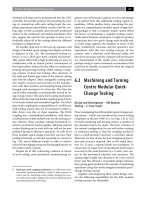
Fig. 20 Robot
gripper arm used to maneuver and orient an aluminum aircraft section with the aid of a video
camera that helps it see the workpiece and then identifies it from a data base. Courtesy of Lockheed-
California
Company
Additional Applications
As machine vision technology evolves and becomes more widely used within industry, additional applications are
beginning to emerge. Many of these applications represent special-purpose equipment that has been designed to satisfy a
particular need, while others combine two or more of the previously mentioned functions (visual inspection, part
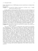
identification, and guidance and control). For example, the system shown in Fig. 21 can inspect as well as sort various
fasteners and similar multiple-diameter parts. Still other applications reflect machine vision systems that are incorporated
into other equipment.
Fig. 21 Noncontact digital computer-vision-
based fastener inspection system used to gage and then sort parts.
Unit measures 11 parameters for up to 24 different fas
teners that are stored in a memory and is capable of
sorting up to 180 parts per minute or over 10,000 parts per hour. Courtesy of Diffracto Limited
Special-Purpose Systems. In the future, special-purpose systems are likely to represent a large, if not the largest, use
of machine vision technology. One of the best examples of this type of system is equipment for inspecting PCBs. A
number of companies have either developed or are in the process of developing such systems, which are expected to be
widely used by the end of the decade. Similar special-purpose equipment is entering the market for the inspection of
thick-film substrates and circuits, surface-mounted devices, and photolithographic artwork.
Embedded Technology. In the embedded technology are, one of the major uses of machine vision is mask alignment
for the production of microelectronic devices. Similarly, vision technology is also becoming widely used for controlling
other microelectronic fabrication equipment, such as the automation of wire-bonding machines for connecting integrated
circuits to their case. In the future, these two thrusts special-purpose systems and embedded vision technology should
result in numerous applications unheard of today.
Reference cited in this section
1.
"Machine Vision Systems: A Summary and forecast," 2nd ed., Tech Tran Consultants, Inc., 1985
Machine Vision and Robotic Inspection Systems
John D. Meyer, Tech Tran Consultants, Inc.
Future Outlook
The potential for using machine vision in manufacturing applications is enormous. Many inspection operations that are
now performed manually could be automated by machine vision, resulting in both reduced costs and improved product
quality. However, before machine vision can reach its full potential, several basic improvements in the technology must
be made.
Limitations of Current Systems
At the present time, there are six key issues that must be addressed by vision system developers. Many organizations are
attempting to resolve these issues through such developments as improved computer hardware or improved software
algorithms, but much work remains to be done to develop effective vision systems that are available at a reasonable cost.
The following issues represent basic limitations of commercial vision systems:
• Limited 3-D interpretation
• Limited interpretation of surfaces
• Need for structured environment
• Long processing time
• High cost
• Excessive applications engineering
Limited 3-D Interpretation. Most commercial vision systems are two dimensional; that is, they make conclusions
about objects from data that are essentially two-dimensional in nature. In many manufacturing situations, an outline of the
shape of an object is sufficient to identify it or to determine whether an inspection standard has been achieved. However,
in many other operations, such as the inspection of castings, this information is not sufficient. Many more sophisticated
operations could be performed with vision systems if the three-dimensional shape of an object could be inferred from an
image or a series of images. To accomplish this, vision system suppliers will need to incorporate more sophisticated data
interpretation algorithms along with improved system performance (resolution, speed, and discrimination).
Limited Interpretation of Surfaces. Complex surface configurations on objects, such as textures, shadows, and
overlapping parts, are difficult for vision systems to interpret. Improved gray-scale image formation capabilities have
helped somewhat, but vision systems are extremely limited in their ability to analyze the large amounts of data provided
by gray-scale image formation. The ability to accurately interpret light intensity variations over the surface of an object,
which is so fundamental to human vision, must be refined if vision systems are to be used for such applications as object
recognition or inspection from surface characteristics.
Need for Structured Environment. Although vision systems, being a form of flexible automation, should be able to
eliminate the need for elaborate jigs and fixtures, they still require a relatively orderly environment in most current
applications. Vision systems have difficulty dealing with overlapping or touching parts; therefore, workpieces must be
presented one at a time to the system. Ideally, a vision system should be able to examine parts as humans do by studying
key features no matter how the part is oriented and even if some portions of the parts are obstructed by other overlapping
parts.
Long Processing Time. There are constraints on the speed of the manufacturing operation in which a vision system
can be used. Only a limited number of real-time (30 images per second) systems have begun to appear on the market.
However, most real-time systems are used for simple applications rather than more complex tasks. There is generally a
trade-off between the processing time required and the degree of complexity of a processing cycle. An ideal vision system
would be capable of performing complex three-dimensional analyses of objects, including surface features, in real time.
High Cost. Although payback periods for vision systems are generally good (1 year or less for some applications), the
basic purchase price of many systems is still prohibitively high to promote widespread use of this technology within the
manufacturing industry.
Extensive Applications Engineering. It is still nearly impossible to purchase an off-the-shelf vision system and
apply it without considerable assistance from a vendor, consultant, or in-house engineering staff. This is partly due to the
complexity of real-world applications. Other factors include the limitations of current equipment and the lack of trained
personnel within user organizations. Application engineering cost and risk and a shortage of trained technical personnel
are major barriers to widespread use of industrial vision systems.
Future Developments
Many developmental programs are underway, both in private industry as well as in universities and other research
organizations, to develop advanced vision systems that are not subject to the limitations discussed previously.
The solution to these problems is likely to emerge from several important developments expected to occur during the next
decade; these developments are discussed in the following sections. However even if no further improvements are made
in machine vision systems, the number of systems in use would continue to grow rapidly. Machine vision systems are
beginning to be introduced into applications for which they previously would have not even been considered, because of
the complexity of the manufacturing process.
Improved Camera Resolution. As solid-state cameras with arrays of 512 × 512 or even 1024 × 1024 pixels are used,
image resolution will improve. As a result, the ability of vision systems to sense small features on the surfaces of objects
should also improve.
Ability to Sense Color. A few developmental vision systems are already available that sense color. The addition of
this capability to commercial vision systems would allow the measurement of one more feature in identifying objects. It
would also provide a greater degree of discrimination in analyzing surfaces.
Effective Range Sensing. This is a prerequisite for three-dimensional interpretation and for certain types of robot
vision. Based on research such as that being performed on binocular vision, it is likely that a range-sensing capability will
become a standard feature of commercial vision systems within a few years.
Ability to Detect Overlap. This capability will approve the ability of vision systems to interpret surfaces and three-
dimensional objects. It will also provide a greater degree of flexibility for vision systems. There will no longer be a need
to ensure that moving parts on a conveyor are not touching or overlapping, and this will reduce the amount of structure
required.
Improved Gray-Scale Algorithms. As vision system hardware becomes capable of forming more complex images,
the software algorithms for interpreting these images will improve, including the ability to infer shape from changes in
light intensity over an image.
Robot Wrist-Mounted Vision System. Based on work being performed at a number of organizations, it is likely that
an effective wrist-mounted vision system will be available within the next few years. Mounting the camera on the robot's
wrist provides the advantage of greatly reducing the degree of structure required during such operations as robot-
controlled welding, assembly, or processing.
Motion-Sensing Capability. There are two elements being developed in this area. First is the ability of a vision
system to create and analyze an image of a moving object. This requires the ability to freeze each frame without blurring
for analysis by the computer. Second is the more complex problem of determining the direction of motion of an object
and even the magnitude of the velocity. This capability will be valuable in such applications as collision avoidance or
tracking moving parts.
Parallel Processing of Whole Image. One of the most promising methods of approaching a real-time processing
capability is the use of a parallel processing architecture. Several systems currently on the market offer this type of
architecture. This approach is likely to be used more extensively in the future.
Standardized Software Algorithms. Although some standard vision system application algorithms are available,
most programs for current manufacturing applications are custom designed. It is likely that standard programs will
become increasingly available for standard application. In addition, programming languages will continue to become
more user oriented.
Computers Developed Specifically for Vision Systems. Most vision systems today use standard off-the-shelf
computers, which tends to limit the data analysis capabilities of the vision system, In the future, especially as sales
volumes increase, it is likely that computers will be designed specifically for dedicated use with a vision system. This will
reduce processing times and help to reduce system prices. Several systems have been developed with this type of custom
computer architecture.
Hard-Wired Vision Systems. To overcome the problem of processing speed, some researchers have suggested the
use of hard-wired circuitry rather than microprocessor-based systems. This would significantly speed up image processing
times, but may result in less system flexibility and limited capabilities.
Special-Purpose Systems. As discussed previously, there is a growing trend toward special-purpose, rather than
general-purpose, vision systems. This permits the system developer to take advantage of prior knowledge concerning the
application and to provide only the features and capabilities required, resulting in more cost-effective systems. A number
of vendors have already begun to offer special-purpose systems for such applications as weld seam tracking, robot vision,
and PCB inspection.
Integration with Other Systems. One of the major problems with the current vision systems is the difficulty in
interfacing them with other types of equipment and systems. A number of companies and research organizations are
attacking this problem, particularly with respect to special-purpose vision systems.
Optical Computing. It is possible to perform image processing using purely optical techniques, as opposed to the
traditional approach of converting an image into an electrical signal and analyzing this symbolic representation of the
image. In the optical domain, processing steps such as the computation of Fourier transforms take place almost
instantaneously. Although optical computing techniques offer considerable promise, it will take a number of years before
they become a practical reality.
Custom Microelectronic Devices. As the sales volume for vision systems continues to grow, it will become
increasingly feasible to implement portions of the system design in custom microelectronic circuits. This will be
particularly true for low-level image-processing functions, such as histogram calculations, convolutions, and edge
detectors. Such chips should be available within the next few years.
Innovative Sensor Configurations. A number of researchers are working on unique vision sensors to improve
overall performance. This includes novel sensor configurations, such as annular arrangements of detector elements, as
well as other camera concepts, such as multiple spectral detectors that sense energy in more than one portion of the
electromagnetic spectrum.
Visual Servoing. Several researchers are studying the use of vision systems as an integral feedback component in a
motion control system, such as a robot vision system for positioning the manipulator arm. Although vision systems are
currently used for robot guidance and control, this is usually accomplished outside the control loop. In visual servoing, on
the other hand, the vision system would serve as a position-sensing device or error measurement component on a real-
time basis.
Machine Vision and Robotic Inspection Systems
John D. Meyer, Tech Tran Consultants, Inc.
References
1. "Machine Vision Systems: A Summary and forecast," 2nd ed., Tech Tran Consultants, Inc., 1985
2. P. Dunbar, Machine Vision, Byte, Jan 1986
Machine Vision and Robotic Inspection Systems
John D. Meyer, Tech Tran Consultants, Inc.
Selected References
• I. Aleksander, Artificial Vision for Robots, Chapman and Hall, 1983
• D. Ballard and C. Brown, Computer Visions, Prentice-Hall, 1982
• J. Brady, Computer Vision, North-Holland 1982
• O. Faugeras, Fundamentals of Computer Vision, Cambridge University Press, 1983
• J. Hollingum, Machine Vision: Eyes of Automation, Springer-Verlag, 1984
• A. Pugh, Robot Vision, Springer-Verlag, 1983
Guide to Nondestructive Evaluation Techniques
John D. Wood, Lehigh University
Introduction
NONDESTRUCTIVE EVALUATION (NDE) comprises many terms used to describe various activities within the field.
Some of these terms are nondestructive testing (NDT), nondestructive inspection (NDI), and nondestructive examination
(which has been called NDE, but should probably be called NDEx). These activities include testing, inspection, and
examination, which are similar in that they primarily involve looking at (or through) or measuring something about an
object to determine some characteristic of the object or to determine whether the object contains irregularities,
discontinuities, or flaws.
The terms irregularity, discontinuity, and flaw can be used interchangeably to mean something that is questionable in the
part or assembly, but specifications, codes, and local usage can result in different definitions for these terms. Because
these terms all describe what is being sought through testing, inspection, or examination, the term NDE (nondestructive
evaluation) has come to include all the activities of NDT, NDI, and NDEx used to find, locate, size, or determine
something about the object or flaws and allow the investigator to decide whether or not the object or flaws are acceptable.
A flaw that has been evaluated as rejectable is usually termed a defect.
Guide to Nondestructive Evaluation Techniques
John D. Wood, Lehigh University
Selection of NDE Methods
The selection of a useful NDE method or a combination of NDE methods first necessitates a clear understanding of the
problem to be solved. It is then necessary to single out from the various possibilities those NDE methods that are suitable
for further consideration; this is done by reviewing the articles in this Volume and in the technical literature.
Several different ways of comparing the selected NDE methods are presented in this article, but there is no completely
acceptable system of comparison, because the results are highly dependent on the application. Therefore, it is
recommended that a comparison be developed specifically for each NDE area and application. The final validation of any
NDE protocol will depend on acceptance tests conducted using appropriate calibration standards.
Nondestructive evaluation can be conveniently divided into nine distinct areas:
• Flaw detection and evaluation
• Leak detection and evaluation
• Metrology (measurement of dimension) and evaluation
• Location determination and evaluation
• Structure or microstructure characterization
• Estimation of mechanical and physical properties
• Stress (strain) and dynamic response determination
• Signature analysis
• Chemical composition determination
Because two of these areas signature analysis and chemical composition determination are usually not considered when
NDE applications are discussed and are therefore not covered in this Volume, they will not be discussed further.
Information on these subjects can, however, be found in Materials Characterization, Volume 10 of ASM Handbook,
formerly 9th Edition Metals Handbook. The remaining seven areas are vastly different and therefore will be covered
separately, along with a discussion of the selection of specific NDE methods
*
for each.
Note cited in this section
*
Throughout this article the term method is used to describe the various nondestructive testing disciplines
(for example, ultrasonic testing) within which variou
s test techniques may exist (for example, immersion or
contact ultrasonic testing).
Guide to Nondestructive Evaluation Techniques
John D. Wood, Lehigh University
Flaw Detection and Evaluation
Flaw detection is usually considered the most important aspect of NDE. There are many conceivable approaches to
selecting NDE methods. One approach is to consider that there are only six primary factors involved in selecting an NDE
method(s):
• The reason(s) for performing the NDE
• The type(s) of flaws of interest in the object
• The size and orientation of flaw that is rejectable
• The anticipated location of the flaws of interest in the object
• The size and shape of the object
• The characteristics of the material to be evaluated
The most important question to be answered before an NDE method can be selected is, What is the reason(s) for choosing
an NDE procedure? There are a number of possible reasons, such as:
• Determining whether an object is acceptable after each fabrication step; this can be called in-
process
NDE or in-process inspection
•
Determining whether an object is acceptable for final use; this can be called final NDE or final
inspection
•
Determining whether an existing object already in use is acceptable for continued use; this can be called
in-service NDE or in-service inspection
After the reasons for selecting NDE have been established, one must specify which types of flaws are rejectable, the size
and orientation of flaws that are rejectable, and the locations of flaws that can cause the object to become rejectable. The
type, size, orientation, and location of flaws that will cause a rejection must be determined if possible, using stress
analysis and/or fracture mechanics calculations. If definitive calculations are not economically feasible, the type, size, and
orientation of flaw that will cause the object to be rejected must be estimated with an appropriate safety factor.
The type, size, orientation, and location of the rejectable flaw are often dictated by a code, standard, or requirement, such
as the American Society of Mechanical Engineers Pressure Vessel Code, a Nuclear Regulatory Commission requirement,
or the American Welding Society Structural Welding Code. If one of these applies to the object under consideration, the
information needed will be available in the appropriate document.
Volumetric and Planar Flaws. Once the size and orientation of the rejectable flaw have been established, it is
necessary to determine which types of flaws are rejectable. In general, there are two types of flaws: volumetric and
planar. Volumetric flaws can be described by three dimensions or a volume. Table 1 lists some of the various types of
volumetric flaws, along with useful NDE detection methods. Planar flaws are thin in one dimension but larger in the other
two dimensions. Table 2 lists some of the various types of planar flaws, along with appropriate NDE detection methods.
Table 1 Volumetric flaw classification and NDE detection methods
Volumetric flaws
Porosity
Inclusions
Slag
Tungsten
Other
Shrinkage
Holes and voids
Corrosion thinning
Corrosion pitting
NDE detection methods
Visual (surface)
Replica (surface)
Liquid penetrant (surface)
Magnetic particle (surface and subsurface)
Eddy current
Microwave
Ultrasonic
Radiography
X-ray computed tomography
Neutron radiography
Thermography
Optical holography
Speckle metrology
Digital image enhancement (surface)
Table 2 Planar flaw classification and NDE detection methods
Planar flaws
Seams
Lamination
Lack of bonding
Forging or rolling lap
Casting cold shut
Heat treatment cracks
Grinding cracks
Plating cracks
Fatigue cracks
Stress-corrosion cracks
Welding cracks
Lack of fusion
Incomplete penetration
Brazing debond
NDE detection methods
Visual
Replication microscopy
Magnetic particle
Magnetic field
Eddy current
Microwave
Electric current perturbation
Magabsorption
Ultrasonic
Acoustic emission
Thermography
Flaw Location, Shape, and Size. In addition to classifying flaws as volumetric or planar, it is necessary to consider
the locations of the flaws in the object. Flaws can be conveniently classified as surface flaws or as interior flaws that do
not intercept the surface. Table 3 lists NDE methods used to detect surface and interior flaws.
Table 3 NDE methods for the detection of surface and interior flaws
Surface
Visual
Replica
Liquid penetrant
Magnetic particle
Magnetic field
Electric current
Magabsorption
Eddy current
Ultrasonic
Acoustic emission
Thermography
Optical holography
Speckle metrology
Acoustic holography
Digital image enhancement
Acoustic microscopy
Interior
Magnetic particle (limited use)
Magnetic field
Electric current perturbation
Magabsorption
Eddy current
Microwave
Ultrasonic
Acoustic emission
Radiography
X-ray computed tomography
Neutron radiography
Thermography (possible)
Optical holography (possible)
Acoustic holography (possible)
Two additional factors that affect NDE method selection are the shape and size of the object to be evaluated. Tables 4 and
5 compare NDE techniques for varying size (thickness) and shape.
Table 4 Comparison of NDE methods based on size of object to be evaluated
The thickness or dimension limitation is only approximate because the exact value depends on the specific physical properties of the
material being evaluated.
Surface only but independent of size
Visual
Replica
Digital enhancement
Liquid penetrant
Shallow depth or thin object (thickness 1 mm, or 0.04 in.)
Magnetic particle
Magnetic field
Magabsorption
Eddy current
Increased thickness (thickness 3 mm, or 0.12 in.)
Microwave
Optical holography
Speckle metrology
Acoustic holography
Acoustic microscopy
Increased thickness (thickness 100 mm, or 4 in.)
X-ray computed tomography
Increased thickness (thickness 250 mm, or 10 in.)
Neutron radiography
(a)
X-ray radiography
Thickest (dimension 10 m, or 33 ft)
Ultrasonic
(a)
All NDE methods suitable for thick objects can be used on thin objects, except neutron radiography, which is not useful for most thin objects.
Table 5 Comparison of NDE techniques based on shape of object to be evaluated
Simplest shape
Optical holography
Acoustic holography
Acoustic microscopy
Thermography
Microwave
Eddy current
Magnetic particle
Magnetic field
Magabsorption
Neutron radiography
X-ray radiography
Ultrasonic
Liquid penetrant
Digital enhancement
Replica
Visual
X-ray computed tomography
Most complex shape
The characteristics of the material that may affect NDE method selection are highly dependent on the specific NDE
method under consideration. Table 6 lists a number of NDE methods and the characteristic of critical importance for each.
Table 6 NDE methods and their important material characteristics
Method Characteristic
Liquid penetrant Flaw must intercept surface.
Magnetic particle Material must be magnetic.
Eddy current Material must be electrically conductive or magnetic.
Microwave Microwave transmission
Radiography and x-ray computed tomography
Changes in thickness, density, and/or elemental composition
Neutron radiography Changes in thickness, density, and/or elemental composition
Optical holography Surface optical properties
The specific NDE method can be selected by applying all the previously discussed factors. Because each NDE method
has a specific behavior, it is often desirable to select several NDE methods having complementary detection capabilities.
For example, ultrasonic and radiographic methods can be used together to ensure the detection of both planar flaws (such
as cracks) and volumetric flaws (such as porosity).
Guide to Nondestructive Evaluation Techniques
John D. Wood, Lehigh University
Leak Detection and Evaluation
Because many objects must withstand pressure, the nondestructive determination of leakage is extremely important. The
NDE area known as leak detection utilizes many techniques, as described in the article "Leak Testing" in this Volume.
Each technique has a specific range of applications, and a particular leak detection technique should be selected only after
careful consideration of the factors discussed in the article "Leak Testing".
Guide to Nondestructive Evaluation Techniques
John D. Wood, Lehigh University
Metrology and Evaluation
The measurement of dimensions, referred to as metrology, is one of the most widely used NDE activities, although it is
often not considered with other conventional NDE activities, such as flaw detection. Although conventional metrology is
not specifically discussed in this Volume, modern high-technology metrology is covered in the articles "Laser
Inspection," "Coordinate Measuring Machines," and "Machine Vision and Robotic Evaluation."
The selection of a metrology system is highly dependent on the specific requirements of a given application. Standard
reference works on the topic should be consulted for conventional metrology, and the articles "Laser Inspection,"
"Coordinate Measuring Machines," and "Machine Vision and Robotic Evaluation." should be studied for selecting new
technology. In addition, other NDE methods, such as eddy current, ultrasonic, optical holography, and speckle metrology,
often find application in the field of metrology. Selection of these methods for metrology application can be assisted by
the information in the articles "Eddy Current Inspection," "Ultrasonic Inspection," "Optical Holography," and "Speckle
Metrology" in this Volume.
Guide to Nondestructive Evaluation Techniques
John D. Wood, Lehigh University
Location Determination and Evaluation
An occasional problem is whether an assembled unit (one that contains several parts) actually contains the necessary
components. This type of inspection has resulted in an NDE activity that can be termed location determination. The most
commonly employed NDE techniques for location determination are x-ray radiography, x-ray computed tomography, and
neutron radiography. These techniques and their selection are discussed in separate articles in this Volume.
Guide to Nondestructive Evaluation Techniques
John D. Wood, Lehigh University
Structure or Microstructure Characterization
Another interesting area of NDE is microstructural characterization, which can be done in situ without damaging the
object by using replication microscopy (discussed in the article "Replication Microscopy Techniques for NDE" in this
Volume) or by using conventional optical microscopy techniques with portable equipment, including polishing, etching,
and microscopic equipment. In addition, it is possible to characterize the microstructure through the correlation with some
type of NDE information. For example, the transmission of ultrasonic energy has been correlated with the microstructure
of gray cast iron.
Microstructure can often be characterized by determining physical or mechanical properties with NDE techniques
because there is usually a correlation among microstructure, properties, and NDE response. Characterizing microstructure
from NDE responses is a relatively recent area of NDE application, and new developments are occurring frequently.
Guide to Nondestructive Evaluation Techniques
John D. Wood, Lehigh University
Estimation of Mechanical and Physical Properties
As discussed previously, the prediction of mechanical and physical properties with NDE techniques is a relatively new
application of NDE. Eddy current, ultrasonic, x-ray and neutron radiography, computed tomography, thermography, and
acoustic microscopy phenomena are affected by microstructure, which can be related to some mechanical or physical
properties. In addition, microwave NDE can be related to the properties of plastic materials. Several technical meetings
are held each year to discuss advances in NDE, and these meetings often feature session on characterizing microstructure
and mechanical and physical properties with NDE techniques. Some of the meetings are listed below:
• Annual Review (every spring), Center for Nondestructive Evaluation, The Johns Hopkins University
•
Annual Review of Progress in Quantitative NDE (every summer), The Center for NDE, Iowa State
University
• Symposium on Nondestructive Evaluation (every other spring), Nondestructive Testing Inform
ation
Center, Southwest Research Institute
• Spring and Fall Meetings, American Society for Nondestructive Testing
Guide to Nondestructive Evaluation Techniques
John D. Wood, Lehigh University
Stress/Strain and Dynamic Response Determination
The local strain at a specific location in an object under a specific set of loading conditions can be determined by using
strain sensing methods such as photoelastic coatings, brittle coatings, or strain gages. These methods are discussed in the
article "Strain Measurement for Stress Analysis" in this Volume. If the stress-strain behavior of the material is known,
these strain values can be converted into stress values.
A number of methods have also been developed for measuring residual stresses in materials. These include x-ray
diffraction, ultrasonics, and electromagnetics. Surface residual stresses can be measured by x-rays as described in the
article "X-Ray Diffraction Residual Stress Techniques" in Materials Characterization, Volume 10 of ASM Handbook,
formerly 9th Edition Metals Handbook. Practical application of ultrasonic techniques for characterizing residual stresses
have not yet materialized. A number of electromagnetic techniques have, however, been successfully used as described in
the articles "Electromagnetic Techniques for Residual Stress Measurements" and "Magabsorption NDE" in this Volume.
Dynamic behavior of an object can be evaluated during real or simulated service by employing strain sensing technology
while the object is being dynamically loaded. In addition, accelerometers and acoustic transducers can be used to
determine the dynamic response of a structure while it is being loaded. This dynamic response is called a signature and
evaluation of this signature is called signature analysis. The nature of this signature can be correlated with many causes,
such as machine noise, vibrations, and structural instability (buckling or cracking).
Replication Microscopy Techniques for NDE
A.R. Marder, Energy Research Center, Lehigh University
Introduction
SURFACE REPLICATION is a well-developed electron microscopy sample preparation technique that can be used to
conduct in situ measurements of the microstructure of components. The in situ determination of microstructural
deterioration and damage of materials subjected to various environments is an objective of any nondestructive evaluation
(NDE) of structural components. The need to assess the condition of power plant and petrochemical metallic components
on a large scale recently led to the application of surface replication to the problem of determining remaining life. The
usual method of metallographic investigation, which may involve cutting large pieces from the component so that
laboratory preparation and examination can be performed, usually renders the component unfit for service or necessitates
a costly repair. As a result, metallographic investigations are avoided, and important microstructural information is not
available for evaluating the component for satisfactory performance. Therefore, an in situ or field microscopy
examination is needed to aid in the proper determination of component life.
The replica technique for the examination of surfaces has been extensively used for studying the structure of polished-
and-etched specimens and for electron fractographic examination (see the article "Transmission Electron Microscopy" in
Fractography, Volume 12 of ASM Handbook, formerly 9th Edition Metals Handbook for a discussion of replication
techniques in fractography). Surface replication was the predominant technique in electron microscopy prior to being
supplemented by thin-foil transmission and scanning electron microscopy. Recently, the replication microscopy technique
has become an important NDE method for microstructural analysis, and an American Society for Testing and Materials
specification has been written for its implementation (Ref 1).
Acknowledgements
The author would like to acknowledge the contributions of his colleagues A.O. Benscoter, S.D. Holt, and T.S. Hahn in the
preparation of this article.
Reference
1.
"Standard Practice for Production and Evaluation of Field Metallographic Replicas," E 512-87,
Annual Book
of ASTM Standards, American Society for Testing and Materials
Replication Microscopy Techniques for NDE
A.R. Marder, Energy Research Center, Lehigh University
Specimen Preparation
Mechanical Polishing Methods. Components in service usually have a well-developed corrosion or oxidation
product or a decarburized layer on the surface that must be removed before replication. Coarse-grinding equipment can be
used as long as the proper precautions are taken to prevent the introduction of artifacts into the structure due to
overheating or plastic deformation. Sandblasting, wire wheels, flap wheels, and abrasive disks have all been used. After
the initial preparation steps are completed, standard mechanical polishing techniques can be used. Field equipment is
commercially available to help the metallographer reproduce the preparation steps normally followed in the laboratory.
Depending on the material, various silicon carbide abrasive disks of different grit size, together with polishing cloth disks
with diamond paste or alumina of varying grit size, can be used to prepare for the etching step. Finally, any appropriate
etchant for the material being examined can be applied to develop the microstructure. For the proper identification of such
microstructural features as creep cavities, a maximum double or triple etch-polish-etch procedure should be used (Ref 2).
The etchants used for the various materials investigated by the replication technique are described in Metallography and
Microstructures, Volume 9 of ASM Handbook, formerly 9th Edition Metals Handbook and in Ref 3.
Electrolytic Preparation Technique. Although electrolytic polishing and etching techniques have often been
employed as the final mechanical polish step in sample preparation, inherent problems still exist in this process. The
electropolishing technique uses an electrolytic reaction to remove material to produce a scratch-free surface. This is done
by making the specimen the anode in an electrolytic cell. The cathode is connected to the anode through the electrolyte in
the cell. Specimens can be either polished or etched, depending on the applied voltage and current density, as seen in the
fundamental electropolishing curve in Fig. 1. However, the pitting region must be avoided so that artifacts are not
introduced into the microstructure. It is virtually impossible to prevent pitting without precise control of the polishing
variables, and pits can often be mistakenly identified as creep voids.
Fig. 1 Current density-voltage curve for electropolishing
Several portable electropolishing units are commercially available. The most important variables (time, bath temperature,
electrolyte composition, and the current density-voltage relationship) have been investigated for a selected group of
electrolytes (Ref 4). A direct comparison of electropolishing units and the precautions necessary for handling certain
electrolytes are given in Ref 5.
It should be noted that there are areas in both fossil and nuclear plants in which neither acid etches nor electropolishing
methods and materials are allowed because of the potential for intergranular stress-corrosion cracking. Stainless steel
piping in nuclear plants can be replicated to determine defects by manual polishing without etchants. Generator retaining
rings have been replicated by manual polishing to resolve NDE indications, because they are extremely sensitive to stress-
corrosion cracking and no acids or caustics are allowed to be used (Ref 6).
References cited in this section
2.
A.M. Bissel, B.J. Cane, and J.F. DeLong, "Remanent Life Assessment of Seam
Welded Pipework," Paper
presented at the ASME Pressure Vessel and Piping Conference, American Society of Mechanical Engineers,
June 1988
3.
G.F. Vander Voort, Metallography: Principles and Practice, McGraw-Hill, 1984
4.
T.S. Hahn and A.R. Marder, Effect of Electropolishing Variables on the Current Density
Voltage
Relationship, Metallography, Vol 21, 1988, p 365
5.
M. Clark and A. Cervoni, "In Situ Metallographic Examination of Ferrous and Non-
Ferrous Components,"
Canadian Electrical Association, Nov 1985
6.
J.F. DeLong, private communication
Replication Microscopy Techniques for NDE
A.R. Marder, Energy Research Center, Lehigh University
Replication Techniques
Replication techniques can be classified as either surface replication or extraction replication. Surface replicas provided
an image of the surface topography of a specimen, while extraction replicas lift particles from the specimen. The
advantages and disadvantages of some typical replication techniques are given in Table 1.
Table 1 Comparison of replica techniques
Type Advantages
Disadvantages
Surface replicas
Acetate Excellent resolution
Coating required
Acrylic Direct viewing
Adhesion
Rubber Easy removal
Resolution
Extraction replicas
Direct stripped plastic
Easy preparation
Particle retention
Positive carbon Excellent particle retention with two-stage etching
Coating required
Direct carbon Excellent resolution Not applicable to in situ studies
Surface Replicas. Replication of a surface can involve either direct or indirect methods. In the direct, or single-stage,
method, a replica is made of the specimen surface and subsequently examined in the microscope, while in the indirect
method, the final replica is taken from an earlier primary replica of the specimen surface. Only the direct method will be
considered in this article because it lends itself more favorably to on-site preparation. The most extensively used direct
methods involve plastic, carbon, or oxide replica material. All direct methods except plastic methods are destructive and
therefore require further preparation of the specimen before making additional replicas.
Plastic replicas lend themselves to in-plant nondestructive examination because of their relative simplicity and short
preparation time. Plastic replicas can be examined with the light optical microscope, the scanning electron microscope,
and the transmission electron microscope, depending on the resolution required. As illustrated in Fig. 2, the plastic replica
technique involves softening a plastic film in a solvent, applying it to the surface, and then allowing it to harden as the
solvent evaporates. After careful removal from the surface, the plastic film contains a negative image, or replica, of the
microstructure that can be directly examined in the light microscope or, after some preparation, in the electron
microscope. Double-faced tape is used to bond the replica to the glass slide in order to obtain large, flat, undistorted
replica surfaces.
Fig. 2 Schematic of the plastic replica technique
There are some significant advantages of the replica technique over the use of portable microscopes in the field (Ref 5):
• A permanent record of the specimen is obtained
• Better resolution and higher magnification can be used
• Contamination of the polished surface is minimized
• Time spent in an unpleasant or hazardous environment is minimized
• Scanning electron microscopy can be utilized
Several materials, including acetate, acrylic resin, and rubber, can be used in the surface replica technique (Ref 5). The
choice of material depends on the geometry of the component and the microstructural features to be examined.
In the acetate method, an acetate tape is wetted with acetone and applied to the surface; other less volatile solvents, such
as methyl acetate, can be used when large areas are replicated. For improved resolution, the back side of the replica can
be painted with any fast-drying black paint or ink prior to removal, or for the same effect, evaporated coatings of carbon,
aluminum, or gold can be applied at a shadow angle of 45° to the front side of the replica after removal.
In the acrylic casting resin method, dams are required because a powder is mixed with a liquid on the surface to be
replicated. After hardening, the replica can be examined directly in an optical microscope without further processing. If
adhesion is a problem, a composite replica can be made of an initial layer of Parlodian lacquer before the acrylic layer is
applied.
In the dental impression rubber method, uncured liquid rubber material (for example, GE RTV60 silicon rubber
compound) is poured onto the surface to be replicated and is contained by a dam. After removal, the replica can be
examined directly or can be coated for better resolution.
Extraction Replicas. Several different extraction replica techniques can be used to characterize small particles that are
embedded in a matrix, such as small second-phase particles in a steel (see the article "Analytical Transmission Electron
Microscopy" in Materials Characterization, Volume 10 of ASM Handbook, formerly 9th Edition Metals Handbook).
More detailed descriptions of the various extraction replica techniques can be found in Ref 7 and 8.
After careful preparation of the surface using normal polishing methods, the first step in producing an extraction replica is
to etch the alloy heavily to leave the particles of interest in relief. In the positive carbon extraction replica, as shown in
Fig. 3, a piece of solvent-softened polymeric film (cellulose acetate tape) is pressed onto the surface exposed by this first
etch (Ref 5). Once the solvent has evaporated, one of two steps can be taken. The tape can be carefully pulled from the
specimen to produce a negative of the surface, or the specimen can undergo a second etch to free the particles exposed by
the first etch (Fig. 3). In the second etch, the specimen can be etched through the plastic; most plastics are quite
permeable to etching solutions, and the specimen etches almost as rapidly as without the plastic film (Ref 9). Carbon is
then evaporated in a vacuum onto the plastic replica. The carbon and plastic containing the particles now make up the
positive replica. The cellulose acetate is then dissolved, and the positive carbon replica is allowed to dry. It should be
noted that for the negative carbon extraction replica technique, vacuum deposition of carbon onto the surface of the
specimen is required, and therefore this replica method is not applicable to NDE.
Fig. 3 Positive carbon extraction replication steps. (a) Pl
acement of plastic after the first etch. (b) After the
second etch. (c) After the deposition of carbon. (d) The positive replica after the plastic is dissolved
References cited in this section
5.
M. Clark and A. Cervoni, "In Situ Metallographic Examination of Ferrous and Non-
Ferrous Components,"
Canadian Electrical Association, Nov 1985
7.
D. Kay, Ed., Techniques for Electron Microscopy, Blackwell Scientific Publications, 1965
8.
J.W. Edington, Practical Electron Microscopy in Materials Science, Van Nostrand Rheinhold, 1976
9.
G.N. Maniar and A. Szirmae, in Manual of Electron Metallography Techniques,
STP 547, American Society
for Testing and Materials, 1973
Replication Microscopy Techniques for NDE
A.R. Marder, Energy Research Center, Lehigh University
Microstructural Analysis
Crack determination is important to help establish the root cause of a potential failure in a component. After a
preliminary evaluation of the crack to assess crack shape and length by using magnetic flux or dye penetrant, the replica
method is then used on unetched specimens to assist in the crack evaluation. Figure 4 schematically shows the
propagation of different types of cracks in a steel structure (Ref 10). Each crack has its own characteristics, and it is often
possible to make a correct determination of crack type. It is important to determine whether the crack is the original defect
or has been caused by service conditions or damage. Once the crack type is identified, the proper corrective action, such
as eliminating a corrosive environment or reducing stress levels, can be attempted. Figure 5 shows the replication of
surface cracks in a boiler tube.
Fig. 4 Propagation of different crack types. (a) Creep. (b) Fatigue. (c) Stress corrosion. (d
) Intergranular
corrosion
Fig. 5 Surface crack in a boiler tube. Comparison of the (a) actual microstructure and (b) the repl
ica of the
crack
Creep Damage. Creep defects cause the majority of failures in power plant components operating under stress and
thermal load, and the replica method is especially suitable for the detection of these defects. Therefore, the replica method
has become an especially important tool in the determination of remaining life in such components as boiler tubes, steam
piping, and turbine components. The replica method reveals defects due to creep at a much earlier stage than other NDE
techniques. Creep defects begin as small holes or cavities at grain boundaries or second phases. With time and stress,
these holes or cavities can link up and form cracks that eventually lead to failure of the component (Fig. 6). Creep cracks
are usually very localized, and they form in welds, bends, or other highly stressed regions. Determining the remaining life
of components normally depends on assessments of regular inspections, as indicated in Table 2. Figure 7 shows a
comparison of creep voids in a surface replica and the corresponding bulk microstructure.
Table 2 Creep damage classification
Class
Nature
Action
1 No creep defects
None
2 A few cavities
Reinspection after 20,000 h of service
3 Coalescent cavities
Reinspection after 15,000 h of service
4 Microscopic creep cracks
Reinspection after 10,000 h of service
5 Macroscopic creep cracks
Management must be informed immediately
Source: Ref 11
Fig. 6
Schematic of creep crack formation. Small cavities (a) link up over time (b) and form intergranular
cracks (c) and eventually macrocracks (d)
Fig. 7 Comparison of creep voids in (a) a replica and (b) the actual microstructure
Precipitate Analysis. The detection of various deleterious precipitates in components subjected to high temperature
and stress can lead to improved life assessment analysis of these components. The extraction replication technique is an
excellent nondestructive method of detecting these precipitates.
Sigma phase is a deleterious FeCr compound that can form in some stainless steels, and its presence can severely limit
remaining life. Extraction replicas have been used to determine the amount of σ phase in the microstructure (Ref 12), and
the amount of phase has been directly related to the creep rate (Ref 13). Figure 8 shows an example of phase in an
extraction replica.
Fig. 8 Comparison of σ-phase formation as seen in (a) a replica and (b) the actual microstructure
The composition of carbides, and their stability with time and temperature of exposure, can indicate the remaining life of
a component. Extraction replicas have been used to evaluate carbides, and it has been suggested that changes in
morphology and chemistry can be used to assist the estimation of effective exposure temperature for use in determining
the remaining life of components (Ref 14). Figure 9 shows an example of precipitates extracted from a 200,000-h exposed
sample, together with the accompanying chemical analysis.
Fig. 9 Ex
traction replica of the microstructure (a) and the precipitate microchemical analysis (b) from an
extraction replica
References cited in this section
10.
P.B. Ludwigsen, Non-Destructive Examination, Structure, Sept 1987, p 3
11.
B. Neubauer and U. Wedel
, NDT: Replication Avoids Unnecessary Replacement of Power Plant
Components, Power Eng., May 1984, p 44
12.
F. Masuyama, K. Setoguchi, H. Haneda, and F. Nanjo, Findings on Creep-
Fatigue Damage in Pressure Parts
of Long-Term Service-Exposed Thermal Power Plants, in
Residual Life Assessment Nondestructive
Examination and Nuclear Heat Exchanger Materials, PVP-Vol 98-
1, Proceedings of the Pressure Vessels
and Piping Conference, American Society of Mechanical Engineers, 1985, p 79
13.
T. Fushimi, "Life Evaluat
ion of Long Term Used Boiler Tubes," Paper presented at the Conference on
Boiler Tube Failures in Fossil Plants (Atlanta), Electrical Power Research Institute, Nov 1987
14.
A. Afrouz, M.J. Collins, and R. Pilkington, Microstructural Examination of 1Cr-0.5
Mo Steel During Creep,
Met. Technol., Vol 10, 1983, p 461
Replication Microscopy Techniques for NDE
A.R. Marder, Energy Research Center, Lehigh University
References
1. "Standard Practice for Production and Evaluation of Field Metallographic Replicas," E 512-87,
Annual
Book of ASTM Standards, American Society for Testing and Materials
2.
A.M. Bissel, B.J. Cane, and J.F. DeLong, "Remanent Life Assessment of Seam Welded Pipework," Paper
presented at the ASME Pressure Vessel and Piping Conference, American S
ociety of Mechanical
Engineers, June 1988
3. G.F. Vander Voort, Metallography: Principles and Practice, McGraw-Hill, 1984
4. T.S. Hahn and A.R. Marder, Effect of Electropolishing Variables on the Current Density
Voltage
Relationship, Metallography, Vol 21, 1988, p 365
5. M. Clark and A. Cervoni, "In Situ Metallographic Examination of Ferrous and Non-
Ferrous Components,"
Canadian Electrical Association, Nov 1985
6. J.F. DeLong, private communication
7. D. Kay, Ed., Techniques for Electron Microscopy, Blackwell Scientific Publications, 1965
8. J.W. Edington, Practical Electron Microscopy in Materials Science, Van Nostrand Rheinhold, 1976
9. G.N. Maniar and A. Szirmae, in Manual of Electron Metallography Techniques,
STP 547, American
Society for Testing and Materials, 1973
10. P.B. Ludwigsen, Non-Destructive Examination, Structure, Sept 1987, p 3
11.
B. Neubauer and U. Wedel, NDT: Replication Avoids Unnecessary Replacement of Power Plant
Components, Power Eng., May 1984, p 44
12. F. Masuyama, K. Setoguchi, H. Haneda, and F. Nanjo, Findings on Creep-
Fatigue Damage in Pressure
Parts of Long-Term Service-Exposed Thermal Power Plants, in
Residual Life Assessment Nondestructive
Examination and Nuclear Heat Exchanger Materials, PVP-Vol 98-1, Proceedings of t
he Pressure Vessels
and Piping Conference, American Society of Mechanical Engineers, 1985, p 79
13.
T. Fushimi, "Life Evaluation of Long Term Used Boiler Tubes," Paper presented at the Conference on
Boiler Tube Failures in Fossil Plants (Atlanta), Electrical Power Research Institute, Nov 1987
14. A. Afrouz, M.J. Collins, and R. Pilkington, Microstructural Examination of 1Cr-
0.5Mo Steel During
Creep, Met. Technol., Vol 10, 1983, p 461
Leak Testing
Revised by Gerald L. Anderson, American Gas and Chemical Company
Introduction
LEAK TESTING is the branch of nondestructive testing that concerns the escape or entry of liquids or gases from
pressurized or into evacuated components or systems intended to hold these liquids. Leaking fluids (liquid or gas) can
penetrate from inside a component or assembly to the outside, or vice versa, as a result of a pressure differential between
the two regions or as a result of permeation through a somewhat extended barrier. Leak testing encompasses procedures
for one or a combination of the following:
• Locating (detecting and pinpointing) leaks
• Determining the rate of leakage from one leak or from a system
• Monitoring for leakage
Leak testing is increasing in importance because of the rising value of, and warranties on, manufactured products and
because of the constantly increasing sensitivity of components and systems to external contaminants. Environmental
concerns are causing additional emphasis on leak testing and its conduct.
Leak Testing
Revised by Gerald L. Anderson, American Gas and Chemical Company
Leak Testing Objectives
Like other forms of nondestructive testing, leak testing has a great impact on the safety and performance of a product.
Reliable leak testing decreases costs by reducing the number of reworked products, warranty repairs, and liability claims.
The most common reasons for performing a leak test are:
• To prevent the loss of costly materials or energy
• To prevent contamination of the environment
• To ensure component or system reliability
Terminology. The following terms must be understood in their strict definitions within the field of leak testing:
• Leak: An actual through-
wall discontinuity or passage through which a fluid flows or permeates; a leak
is simply a special type of flaw
• Leakage: The fluid that has flowed through a leak
• Leak rate:
The amount of fluid passing through the leak per unit of time under a given set of conditions;
properly expressed in units of quantity or mass per unit of time
• Minimum detectable leak: The smallest hole or discrete passage that can be detected
• Minimum detectable leak rate: The smallest detectable fluid-flow rate
The amount of leakage required for a leak testing instrument to produce a minimum detectable signal can be determined.
This amount is generally used to indicate the sensitivity of the instrument. Instrument sensitivity is independent of test
conditions, but when an instrument is used in a test, the sensitivity of the test depends on existing conditions of pressure,
temperature, and fluid flow.
Measurement of Leakage. A leak is measured by how much leakage it will pass under a given set of conditions.
Because leakage will vary with conditions, it is necessary to state both the leak rate and the prevailing conditions to define
a leak properly. At a given temperature, the product of the pressure and the volume of a given quantity of gas is
proportional to its mass. Therefore, leak rate is often expressed as the product of some measure of pressure and volume
per unit of time for example, torr liters per second (torr · L/s), micron liters per second ( L/s), and atmosphere cubic
centimeters per second (atm cm
3
/s).
The two most commonly used units of leakage rate with pressure systems are standard cubic centimeters per second (std
cm
3
/s) and its equivalent, standard atmosphere cubic centimeters per second (atm cm
3
/s). The most frequently used unit in
vacuum leak testing is torr liters per second. The recent adoption of the Système International d'Unités (SI) system of
units has resulted in a new measure of leakage, pascal cubic meters per second (Pa · m
3
/s). Another new unit is moles per
second (mol/s), which has the advantage that information concerning temperature implied in other units is automatically
included in this unit. The term used for leak rate in this article is standard atmosphere cubic centimeter per second, where