Volume 17 - Nondestructive Evaluation and Quality Control Part 16 pptx
Bạn đang xem bản rút gọn của tài liệu. Xem và tải ngay bản đầy đủ của tài liệu tại đây (2.66 MB, 80 trang )
This example demonstrates techniques applied to 9.5 mm ( in.) outside diameter stainless steel tubing with a 0.51 mm
(0.020 in.) wall thickness. However, these techniques can be modified to enable detection of intergranular attack and/or
root weld cracking in various materials and sizes.
A 15-MHz Rayleigh (surface) wave transducer is machined with a 4.8 mm ( in.) radius to fit the 9.5 mm ( in.)
outside diameter of the 0.51 mm (0.020 in.) wall thickness tubing to be inspected (Fig. 13a). The transducer is then
positioned on the tubing, as shown in Fig. 13(b). No prior preparation of the sample was required. Mixed-mode shear
wave is induced in the tubing to detect intergranular attack (Fig. 14) using a ring-pattern CRT display (Fig. 15). This
transducer is also very sensitive and can be used for detecting root weld cracks (Fig. 16). The ultrasound instrument will
be set up for monitoring discrete echoes from the root crack. The display produced is shown in Fig. 17.
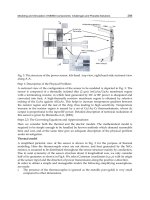
Fig. 13 15-MHz Rayleigh surface wave trans
ducer (90° shear) used for detecting intergranular attack and root
weld cracks. (a) Transducer with radius machined on transducer shoe to allow device to conform to tubing
outside diameter. (b) Transducer positioned on tube outside diameter to couple to tu
be using a lightweight oil
couplant. Source: L.D. Cox, General Dynamics Corporation
Fig. 14 Intergranular attack of 0.51 mm (0.020 in.) wall thickness, Fe-21Cr-6Ni-
9Mn stainless steel tubing
inside diameter. (a) 60×. (b) 85×. Courtesy of L.D. Cox, General Dynamics Corporation
Fig. 15 Mixed-
mode shear wave used to detect intergranular attack showing oscilloscope screen display for (a)
transducer in air, (b) transducer coupled to an acceptable tube having no defects due to intergranular attack,
and (c)
transducer coupled to tube rejected because of intergranular attack. Significant attenuation of the
ultrasonic signal in (c) is due to scatter. Source: L.D. Cox, General Dynamics Corporation
Fig. 16 Cross section of a tube having a crack at the root of the weld seam.
Source: L. D. Cox, General
Dynamics Corporation
Fig. 17
Plots obtained on oscilloscope screen with ultrasonic device set up to monitor discrete echoes from a
root crack: (a) transducer in air; (b) transducer coupled to tube devoid of root
crack defects; and (c)
transducer coupled to tube rejected due to presence of a root crack. Signal A in (b) and (c) is due to reflection
from the transducer/tube OD contact point. Signal B in (c) is the root crack signal [when the transducer is
indexed circumferentially, the A signal will be stationary (no change in time-of-
flight) while the B signal will
shift]. Source: L.D. Cox, General Dynamics Corporation
Example 8: Eddy Current Inspection of Pitting and Stress-Corrosion Cracking of Type
316 Stainless Steel Evaporator Tubes in a Chemical Processing Operation.
Eddy current inspection was performed on a vertical evaporator unit used in a chemical processing plant. The evaporator
contained 180 tubes 25 mm (1 in.) in diameter.
It was advised that the tube material was type 316 stainless steel. The shell side fluid was condensate and gaseous
methylene chloride, while the tube side fluid was contaminated liquid methylene chloride.
Eddy current inspection revealed 101 tubes that exhibited severe outer surface pitting and cracklike indications near each
tube sheet. Several tubes exhibiting strong indications were pulled and examined visually and metallurgically.
It was observed that the indications correlated with rust-stained, pitted, and cracked areas on the outer surfaces. The
observed condition was most severe along the portions of the tubes located between the upper tube support and top tube
sheet. Figures 18(a) and 18(b) show a pitted and cracked area before and after dye-penetration application.
Fig. 18 Pitting and stress corrosion in type 316 stainless steel evaporator tubes. (a) Rust-
stained and pitted
area n
ear the top of the evaporator tube. Not clear in the photograph, but visually discernible, are myriads of
fine, irregular cracks. (b) Same area shown in (a) but after dye-
penetrant application to delineate the extensive
fine cracks associated with the rust-stained, pitted surface. (c) Numerous multibranched, transgranular stress-
corrosion cracks initiating from the outer surface pits. 35×. Courtesy of J.P. Crosson, Lucius Pitkin, Inc.
Metallographic examination revealed that the cracking initiated from the outer surface, frequently at pits, and penetrated
the tube wall in a transgranular, branching fashion. The crack features were characteristic of chloride stress-corrosion
cracking. In many cases, the cracking, rather than penetrating straight through the tube wall, veered off in a tangential
direction at or about mid-wall, suggesting the possibility of a change in the residual stress-field from tube drawing. Figure
18(c) shows stress-corrosion cracking originating from pits on the outer surface of the tube.
The results of the examination indicated that the subject tube failures occurred by way of stress-corrosion cracking as a
result of exposure to a wet-chloride-containing environment. Therefore, a change in tube material was recommended to
avoid future failures and loss of service.
Example 9: Eddy Current Inspection of a Pitted Type 316 Stainless Steel Condenser
Tube.
Eddy current inspection was performed on approximately 200 stainless steel tubes in a main condenser unit aboard a
container ship. The stainless steel tubes comprised the upper two tube rows in the condenser. The tube material was
reported to be type 316 stainless steel; this was confirmed by subsequent chemical analysis. The remaining tubes were
90Cu-10Ni. Recurring leaks had occurred in the stainless steel tubes, but no leaks had occurred in the copper-nickel tubes.
Eddy current indications typical of inner surface pitting were observed in 75% of the stainless steel tubes inspected. A
tube exhibiting a strong indication was pulled from the condenser and examined visually and metallographically.
Visual examination of the outer surface revealed occasional patches of rust-colored deposit at the locations of the eddy
current indications. No apparent defects of any type were observed on the outer surface.
Subsequent splitting of the tube revealed several areas of severe pitting corrosion attack on the inner surface at locations
corresponding to the eddy current indications. The corrosion progressed in such a way as to hollow out the wall thickness,
and at several locations the pits had completely penetrated the wall thickness. The pitting corrosion attack tended to be
close to the bottom of the tube and essentially in line along the tube sample length.
Figure 19(a) shows a severely pitted location. Metallographic examination revealed the attack to be broad and
transgranular in nature without any corrosion product build-up at or around the pits. Figure 19(b) shows the manner in
which the pitting had penetrated into and beneath the inner surface.
Fig. 19
Pitted type 316 stainless steel condenser tube. (a) Inner surface of main condenser tube showing
extensive but localized pitting corrosion attack. 1×. (b) Longitudinal section passing through a pitted area
showing extensive pitting that had progressed beneath the inner surface of the main condenser tube.
55×.
Courtesy of J.P. Crosson, Lucius Pitkin, Inc.
The results of the examination revealed that the subject stainless steel condenser tube had failed as a result of pitting
corrosion attack, which initiated at the inner surface and progressed through the tube wall. That the pitting was essentially
on the bottom of the tubes was strong evidence of deposit-type pitting corrosion attack.
Deposit attack occurs when foreign material carried by the tube side fluid settles or deposits on the inner surface,
generally at the bottom of the tube. The deposit shields the tube surface, creating a stagnant condition in which the fluid
beneath the deposit becomes deficient in oxygen compared to the free-flowing fluid around the deposit. The difference in
oxygen content results in the formation of an oxygen concentration cell in which the smaller, oxygen-deficient sites
become anodic with respect to the larger oxygenated cathodic sites. As a result, pitting corrosion attack occurs at the
anodic sites.
In stainless steel, the condition is further aggravated by the fact that type 316 stainless steel performs best in a service
where the fluid is oxidizing and forms a passive film on the surface of the tube. If there is an interruption in the film, as
may be caused by chemical breakdown through decomposition of organic materials or mechanically by abrasion, and if
the damage film is not reformed, pitting corrosion will initiate and grow at the damaged site. In main condenser service,
certain deposits, such as shells, sand, or decomposing sea life, can initiate breakdown of the passive film.
Example 10: Eddy Current Inspection of a Magnetic Deposit Located on a Steel Tube at
Tube Sheet Joint in a Centrifugal Air-Conditioning Unit.
In this case, defective tubes were not detected. However, the results of the eddy current inspection were directly
influenced by a previous tube failure in the unit.
Eddy current inspection of the condenser bundle of a centrifugal air-conditioning unit revealed several tubes with
indications typical of tube-wall wear at locations corresponding to the tube supports. One of the tubes exhibiting
indications was pulled and visually examined. A tightly adherent magnetic deposit was observed at the area of the tube in
contact with the first tube support. Splitting the tube revealed the deposit to be tightly packed in the fins, as shown in Fig.
20. This tube was of tru-finned rather than skip-finned design; that is, the tube did not have smooth support saddles where
it was in contact with the tube support plate. Instead, the tube was finned from end to end. Therefore, although the test
instrument parameters were selected to phase out the magnetically induced indications from the steel tube supports, the
magnetic deposit, which was tightly embedded between the fins, was closer to the internal test probe and caused an
indication that was interpreted as tube-wall wear.
Fig. 20 Magnetic corrosion product embedded in the tube fin
s at the tube support of a steel tube. The corrosion
product caused by eddy current indication characteristic of tube-wall wear at the support.
Courtesy of J.P.
Crosson, Lucius Pitkin, Inc.
Through further investigation it was determined that a previous tube failure had caused the Freon on the shell side to
become contaminated with water. This condition proved corrosive to the steel supports and shell and subsequently caused
the magnetic corrosion deposit observed at the tube support.
Oil-Country Tubular Products
The application of nondestructive inspection to the tubular products of the oil and gas distribution industry is extensive
and is vital to successful operation. The American Petroleum Institute has, with international cooperation and
international acceptance, developed tubing and pipe specifications that include many rigorous requirements for
nondestructive inspection (Ref 22). Inspection installations range from simple magnetic particle installations to complex
assemblies of machinery whose continuous productivity is completely dependent on the reliability and accuracy of its
nondestructive inspection equipment. The larger installations may use ultrasonic, eddy current, flux leakage, or
radiographic equipment, singly or in combination, and can be supplemented by magnetic particle inspection.
The inspections of pipe or casing can be performed during manufacture, when it is received on site, while it is in service,
or when it must be inspected for reuse or resale. When inspection is included in the manufacturing operation, tests are
usually performed immediately after the pipe is produced and again after processing has been completed.
Industry has promoted the development and use of highly sophisticated equipment for the in-service inspection of pipe in
diameters of 75 mm (3 in.) and larger. In one of several different pipe crawlers available commercially, the probe travels
through the gas lines and, by means of flux leakage measurements, reports on the condition of the pipe. Another type of
in-service inspection unit, which is shown in Fig. 21, includes tight-fitting seals so that it can be propelled through the
pipelines by the oil or gas being carried. The traveling unit includes not only the test instrumentation and a tape recorder
but also a power supply so that it is completely self-sufficient, requiring no connection outside the pipe. The sections of
this unit are connected by universal joints to permit passage around bends. When the unit completes its cycle, total
information on the condition of the pipe is immediately available.
Fig. 21 Self-contained flux leakage inspection unit used in oil and gas pipeline for in-service inspection
One of the most important inspection procedures in this industry involves the inspection of girth welds joining the ends of
pipes to each other or to fittings and bends. Although radiographic tests are widely favored for this application (Ref 23),
supplementary tests are needed to detect the tightly closed flaws not detected by radiography (Ref 12). This industry also
uses automated inspection of small tubular pipe couplings. One machine separates acceptable couplings from rejectable
couplings automatically and requires no operator. The couplings are fed into the machine from a cutoff lathe. After
automatic inspection to API specifications, rejectable couplings are diverted to a reject receptacle.
Nondestructive Inspection of Steel Pipelines (Ref 24)
The nondestructive inspection of welds in steel pipe is used to eliminate discontinuities that could cause failure or
leakage. Most steel pipes for gas transmission are made by the hot rotary forging of pierced billets or by forming plate or
strip and then welding by either the submerged arc or the resistance process. Pipes are usually made to one of the API
specifications, with supplementary requirements if necessary.
Submerged Arc Welded Pipe. The shrinkage of liquid metal upon solidification results in primary piping in the
ingot, which can cause laminations oriented in the plane of the plate or strip rolled from the ingot. Laminations can also
result from secondary piping and from large inclusions. Laminations can nucleate discontinuities during welding or
propagate to form a split in the weld. They cannot be detected by radiography, because of their orientation, but they can
be detected by ultrasonics or can be seen when they occur as skin laminations.
The API specifications do not require nondestructive inspection of the plate or strip before welding, but ultrasonic
inspection is mandatory in some customer requirements. Generally, the periphery of the plates must be examined to
ensure that edges to be welded are free of laminations.
Pulse-echo ultrasonic inspection has been used for most plate-inspection specifications. This method cannot distinguish
laminations near the surface remote from the probe, because the echoes from the laminations cannot be inspected from the
back echo. Some specifications require that the plate be inspected from both surfaces or that transmission methods be
used.
Manual scanning, although time consuming, is feasible because the echo pattern from laminations persists on the
oscilloscope screen and is easy to interpret. However, if laminations are fragmented or at an oblique angle to the surface
of the plate, there is no distinct flaw echo, but merely a loss of back echo. In most pulse-echo equipment, no account is
taken of this loss; therefore, transmission methods are preferable for plate inspection. Such methods normally require
mechanization with automatic recording of the results, and inspection systems based on these methods have been installed
in some plate mills.
In both transmission and pulse-echo inspection, the probe area represents the area of the plate under inspection at any
instant. Shear-wave angle probes are used to detect lamination, but the method is not reliable, particularly for the thin
plates used in pipe manufacture. Laminations can also be detected by ultrasonic Lamb waves, which can inspect a zone
extending across some or all of the plate. Lamb waves have been used on steel sheet, but they cannot be excited in plates
more than 6.4 mm ( in.) thick using standard equipment. Special equipment is now available for plate up to 13 mm (
in.) thick.
The main flaws that occur in submerged arc welds are incomplete fusion and incomplete penetration between the inside
and outside weld beads or between the base metal and the filler metal, cracks, undercut or underfill, and overflow. The
API standards require full-length inspection of welds by radiography or ultrasonics. Fluorescent screens or television
screens are permitted for radiography, and they are often used because they are less expensive than radiographic film,
although less discriminating. Fluoroscopy is inherently less sensitive to the more critical flaws, cracks, incomplete
sidewall fusion, and incomplete penetration. Ultrasonic inspection is more sensitive to serious flaws and can be
automated.
The arrangements of transmitter and receiver probes in ultrasonic inspection of submerged arc welded pipe for detection
of longitudinally and transversely oriented discontinuities are shown in Fig. 22. The region of the oscilloscope time base
corresponding to the weld region is analyzed electronically, and echoes above the amplitude of the reference derived from
the calibration block actuate a relay that can operate visible or audible warnings, paint sprays, or pen recorders. In some
installations, only one probe is used on each side of the weld, and detection of discontinuities that are oriented
transversely to the weld is not possible. To ensure correct lateral positioning of the probes on the weld, they are mounted
on a frame, which is then moved along the weld; alternatively, the pipe can be moved past stationary probes.
Fig. 22 Diagram of arrangements of probe
s in the ultrasonic inspection of submerged arc welded pipe for the
detection of (a) longitudinally oriented and (b) transversely oriented discontinuities
Accurate positioning of the probes over the welds is difficult because the width, shape, and straightness of the weld bead
vary. The inspection area is limited in order to reduce confusion between echoes from flaws within the weld and the
boundaries of the weld reinforcement. Acoustic coupling can be reduced by the probes riding up on weld spatter, by
drifting of the scanning frame, by loss of coupling water, or by loose mill scale.
General practice is to use automatic ultrasonic inspection methods and to radiograph those regions of the pipe suspected
of containing discontinuities. If radiography does not reveal an objectionable flaw, the ultrasonic indication is ignored and
the pipe is accepted. This procedure would accept cracks or laminations parallel to the plate surface that, because of their
orientation, cannot be detected by radiography. As an alternative approach, regions that give an ultrasonic flaw indication
should be inspected radiographically and by manual ultrasonics. If the original ultrasonic indication was from a
discontinuity shown by the radiograph to be acceptable within the specification or if the manual ultrasonic inspection
revealed that the indication was a spurious echo arising from a surface wave or from local weld shape, then the pipe was
accepted; if the radiograph showed an objectionable flaw, then the pipe was rejected. If there was no explanation for the
echo, it was assumed to have arisen from a discontinuity adversely oriented for radiography.
Seamless Pipe. There are two sources of flaws in roll forged seamless pipe: inhomogeneities and the manufacturing
process. Inhomogeneities in the ingot such as primary and secondary ingot pipe can be carried into the roll-forged product
and can cause flaws in a similar manner to the formation of laminations in steel plate. Such flaws are likely to have a
major dimension oriented in the plane of the pipe wall. In manufacturing, the rolls and the mandrel can cause surface
discontinuities such as tears and laps, and such discontinuities will have substantial orientation normal to the pipe wall. In
addition, pipes and tubes produced by working pierced billets are prone to eccentric wall thickness, with the eccentricity
varying along the length of the pipe.
The API specifications that cover seamless line pipe require neither nondestructive inspection nor wall thickness
measurement away from the pipe ends. In some mills, destructive inspections are carried out on samples cut from each
pipe end to determine the presence of primary pipe flaws. In some API standards (casing, tubing, and drill pipe),
nondestructive inspection is optional, but in other standards (high-strength casing and tubing) nondestructive inspection of
the full pipe length is mandatory. Magnetic particle, ultrasonic, or eddy current inspection methods are permitted.
Magnetic particle inspection methods have little or no sensitivity to discontinuities that do not show on the surface
and are likely to detect laminar discontinuities resulting from ingot piping. Although surface laps are amenable to
magnetic crack detection, it would be difficult to apply the inspection method to internal-surface discontinuities.
Eddy current inspection methods can be used to inspect seamless tubing. Very rapid inspection rates are possible
with the encircling-coil system. When pipe is passed through a coil fed with alternating current, the resistive and reactive
components of the coil are modified; the modification depends on dimensions (and therefore indirectly on
discontinuities), electrical conductivity and magnetic permeability, and the annulus between the pipe and the coil (and
therefore the outside diameter of the pipe). The analysis to determine which effect is causing any modification is
complex.
Eddy current methods are extensively used for the inspection of small, nonferrous tubes, but ferrous material causes
complications from magnetic permeability. The initial permeability is affected by residual-stress level. Roll-forged pipe
may have varying amounts of residual cold work, depending on the original soaking conditions and the time taken to
complete forging. The effect can be alleviated by applying a magnetically saturated field; equipment that can produce a
magnetically saturated field has been installed in steel tube mills. However, saturation becomes more difficult as pipe
diameter increases.
Radiographic inspection methods, employing either x-ray or γ-ray transmission, can be used with a scintillation
counter to estimate the wall thickness of pipe. The accuracy of scintillation counters depends on the size of the count for a
given increment of thickness; the count increases with the time the increment is in the beam. As a result, the count, and
therefore the accuracy, increases with decreasing scanning rate. When large-diameter pipes are scanned at realistic rates,
eccentricity is usually averaged out.
Ultrasonic inspection methods can detect discontinuities oriented both in the plane of, and normal to, the pipe wall.
Discontinuities in the plane of the wall can be detected by using a compression-wave probe scanning at normal incidence.
For discontinuities normal to the wall, the beam is converted to shear wave and propagated around or along the tube. The
pipe is rotated and moved longitudinally relative to the probes, thus giving a helical scan.
The reliability of mechanized scanning is a function of acoustic coupling, and optimum results are achieved with
immersion coupling. The efficiency of acoustic coupling through large columns of water is lower but much more
consistent than that through the thin liquid films used in contact scanning. Immersion methods also eliminate probe wear
and the requirement for specially contoured probes to accommodate each pipe size.
Alternatively, immersion coupling by a column of water flowing between the probe and the pipe can be used. With this
method, probe-rotation scanning is possible. Advantage can be taken of the smaller inertia of the probes to increase the
scanning rate, and therefore the speed of inspection, by about an order of magnitude.
When an ultrasonic beam propagates radially through the pipe wall, the time interval between successive back echoes
reflected from the bore surface is directly proportional to the wall thickness. If the first back echo is used to trigger a high-
speed electronic counter whose frequency is such that it will produce a count of 100 during the time taken to receive four
echoes in 25 mm (1 in.) thick plate and if a subsequent back echo is used to stop the counter, a count proportional to the
wall thickness is produced. By changing the frequency of the counter oscillator, it is possible to change the thickness
range inspected or to accommodate different materials. Information from the counter can be fed to a chart recorder, thus
continuously recording the wall thickness. Lamination would be recorded as an abrupt localized reduction in wall
thickness.
For the detection of cracks and laplike discontinuities, the display on the flaw detection oscilloscope is gated. The
discontinuity can then be recorded in its position around the circumference. Chart length can be made proportional to pipe
length, thus facilitating discontinuity location and extent in relation to pipe length and variation in wall thickness around
and along the pipe. Alternatively, information can be monitored in a go/no-go method to provide a paint spray that
identifies the locations of significant discontinuities.
Resistance-Welded Pipe. The type of discontinuity usually responsible for the failure of resistance-welded pipe is
incomplete fusion, with associated oxide film. The nondestructive inspection of larger-diameter resistance-welded pipes is
normally restricted to inspection of the weld region. Systems similar to those used for the inspection of submerged arc
welded seams can be employed, although the arrangements for tracking the probes with respect to the weld
reinforcements are not applicable. Because of problems associated with accurate weld tracking, it is necessary that small
variations in weld-probe separation should only cause acceptably small variations in discontinuity detection sensitivity.
Probe angles of 60 to 65° give satisfactory results, and coverage of the weld depth is achieved by using two probes on
each side of the weld. Such a system is also relevant to the ultrasonic inspection of submerged arc welded pipes.
Nondestructive Inspection of Pipeline Girth Welds
The API specifications do not require that all girth welds be inspected; the use of radiography and the extent of coverage
are optional. Generally, it has been the practice to inspect 10% of the weld length. Where the integrity of a pipeline is
vital, as in high-pressure gas-transmission systems, it is advisable to consider a 100% inspection, especially when
inspection is not a large proportion of the total cost of the pipeline. Where operating conditions are less critical, however,
it may be possible to be less critical regarding the size and type of discontinuity permissible.
Radiographic Inspection. Characteristic discontinuities in pipeline welds are slag, elongated piping in root, scattered
piping and porosity, burn-throughs in the root, incomplete root penetration, incomplete sidewall fusion, and cracks, which
often break the inner surface in the heat-affected zone. Except for cracks and incomplete sidewall fusion, these
discontinuities are amenable to detection by radiography. Open cracks can be detected, but tighter cracks, even though
favorably oriented, are detectable only by optimum practice. Some cracks may not be revealed at all.
Assuming good radiographic techniques, radiographic quality depends on the choice of conditions that control the
contrast and definition of the radiograph; the detection of discontinuities improves with increasing contrast and fine
definition. Contrast can be assessed in terms of the thickness sensitivity, which can be conveniently estimated by image-
quality indicators.
Many factors other than good radiographic techniques influence radiographic contrast. For pipeline radiography, radiation
energy is probably the most important. The absorption of radiation by steel decreases with increasing energy; the
absorption coefficient at 150 kV is about three times that at 700 kV. For optimum detection of small changes in thickness,
the absorption should be as high as possible so that large differences in exposure, consistent with a reasonable amount of
energy being transmitted to provide a realistic overall exposure, result at the film. Gamma radiation from a
192
Ir source is
approximately equivalent to x-rays generated at 700 kV and therefore will not be absorbed sufficiently to give good
contrast sensitivity. For wall thicknesses typical of pipelines, x-rays generated at about 150 to 175 kV have reasonable
absorption.
For the detection and correct identification of discontinuities from the radiographic image, the delineation of the shadow
must be sharp. The principal sources of unsharpness in radiographic images are geometric unsharpness, resulting front the
finite size of radiation sources; unsharpness in the film resulting from the kinetic energy of the radiation, grain size of the
emulsion and degree of development; and unsharpness resulting from the intensifying screen. Radiographs on pipelines
are generally made under less-than-satisfactory conditions; nevertheless, it should be possible to avoid vibration and other
forms of relative movement of the source and film during exposure so that the total geometric unsharpness is the
penumbra effect. With piping, geometric unsharpness is not large.
An important side effect of unsharpness is that when the unsharpness is greater than the width of a flaw, the contrast
resulting from the flaw is reduced from its theoretical value; the greater the unsharpness, the greater the contrast
reduction. For tight cracks, the contrast may be so reduced that the change in tone is below the threshold for detection.
On-site conditions may reduce the capability of radiography to detect flaws. Under some conditions, it is difficult to
maintain correct developer temperature. The operator is often pressured to keep pace with the welding crews; also,
weather and working conditions may be adverse. Suitable equipment and adequate planning should overcome these
problems. The more difficult problem is the repetitiveness of the procedure, which causes the operators to lose
concentration and gradually to devote less attention to detail.
For most pipe sizes it is necessary to make three exposures to cover the circumference of the weld because the length of
weld that can be covered in one exposure (the diagnostic film length) is limited by fade at each end of the film. Panoramic
techniques have been used on some larger-diameter pipes. The source is held in a spider arrangement and positioned on
the pipe axis; the films are placed around the outer surface of the pipe at the weld. In this manner, the entire weld can be
radiographed in one exposure. This exposure is shorter than one of the exposures required in the double-wall, single-
image technique because the radiation has to propagate through only one wall of the pipe. In practice, the radiation source
can be manually positioned only inside pipes having a diameter of 762 mm (30 in.) or more; even then, conditions must
be good. Crawler devices are available that are mechanically propelled through the pipe, with the exposure being operated
from an external control (see the section "In-Motion Radiography" of the article "Radiographic Inspection" in this
Volume).
On pipelines where the rate of welding is low and the investment on crawlers is not justified, x-ray sets can be clamped
onto the outside of the pipe and radiography implemented by the double-wall, single-image technique. Gamma
radiography has been favored for pipeline radiography because of its convenience and lower cost. Source containers are
more compact and portable than x-ray generators and do not require a power supply.
Panoramic x-ray radiography is barely feasible without crawler devices because of the difficulty of manually
maneuvering the cumbersome x-ray sets and control units inside a pipe. Because of the potential for increased use of x-
ray radiography on pipelines, there has been considerable effort applied to development of x-ray crawlers.
Ultrasonic Inspection. Welds are usually ultrasonically inspected by a pulse-echo reflection technique. Before the
inspection of a weld, the pipe should be checked for laminations that may divert the beam from its theoretical path.
Discontinuities can be identified most reliably by accurate positioning of the source of the discontinuity echo, preferably
during scanning from more than one direction. Skilled operators may be able to gain additional information on type of
discontinuity from the shape of the echo on the oscilloscope screen, but the display on battery-operated flaw detectors
used in daylight is not sufficiently distinct for the technique to be employed on pipelines.
The more significant discontinuities occur in the root of the weld, where discrimination between sources of echo
reflection is more difficult. Acceptable features such as full root penetration cause echoes comparable in magnitude to
those from root underbead cracks or incomplete penetration. Accurate positioning of the probe with respect to the weld
centerline is necessary, and it has been suggested that the required accuracy can be achieved only by marking and
machining the pipe ends before welding. Positioning from the center of the weld cap is only approximate because the
weld is not necessarily symmetrical about the centerline through the root. Even with the premarking, it is difficult for an
operator to locate the ultrasonic probe accurately and still be in a position to view the instrument screen. Thinner-wall
pipes reduce the differences in beam path and probe position for discrimination between the various features of the root.
Also, the weld must be examined with the probe-to-weld distance increased to avoid confusion between echoes from the
weld and those from probe noise. This increases the effect of beam spread and may lead to extraneous echoes from the
cap reinforcement.
The skip distance and beam-path length vary as the wall thickness varies. Variations in wall thickness between nominally
the same classes of submerged arc welded pipe range from 10 to 15%, but in seamless pipe a ±10% variation along the
length or around the circumference at a given position along the length is common. Although it is possible to measure
wall thickness accurately by ultrasonics, it is not feasible to measure wall thickness concurrently with scanning the weld.
Surface roughness can cause considerable variations in beam angle. Weld spatter can reduce the effectiveness of the
coupling, and also alter beam angle by lifting part of the probe off the pipe.
Ultrasonic inspection on girth welds was originally used to determine which welds to radiograph. If the radiograph did not
detect anything, it was the practice on most pipelines to accept the radiographic evidence and not that from ultrasonics.
Now that pipelines are being examined 100% by radiography, the role of ultrasonics has changed to that of detecting root
underbead cracks that may escape detection by radiography and of providing supplementary evidence to aid in the
interpretation of radiographic images of weld-root regions.
Surface Crack Detection. Root underbead cracks break the surface of the pipe in the bore and can be detected with
liquid penetrant and magnetic particle inspection. The weld area can be magnetized using a yoke powered by permanent
magnets. Both methods are sensitive under ideal conditions, but liquid penetrants require very clean surfaces. Magnetic
particle crack detection is therefore preferred for pipeline applications. Interpretation of the indications is not a problem,
except for the confusion that may arise from the tendency of sharp changes in root profile to give a slight crack indication.
References cited in this section
12.
R.F. Lumb and G.D. Fearnebaugh, Toward Better Standards for Field Welding of Gas Pipelines, Weld. J.,
Vol 54 (No. 2), Feb 1975, p 63-s to 71-s
19.
F. Förster, Sensitive Eddy-Current Testing of Tubes for Defects on the Inner and Outer Surfaces, Non-
Destr. Test., Vol 7 (No. 1), Feb 1974, p 25-35
21.
V.S. Cecco and C.R. Bax, Eddy Current In-Situ Inspection of Ferromagnetic Monel Tubes, Mater. Eval.,
Vol 33 (No. 1), Jan 1975, p 1-4
22.
"Specification for Line Pipe," API 5L, American Petroleum Institute, 1973
23.
"Standard for Welding Pipe Lines and Related Facilities," API 1104, American Petroleum Institute, 1968
24.
R.F. Lumb, Non-Destructive Testing of High-Pressure Gas Pipelines, Non-Destr. Test., Vol 2 (No. 4),
Nov
1969, p 259-268
Note cited in this section
** Example 7 was prepared by L.D. Cox, General Dynamics Corporation. Examples 8, 9, and 10
were
prepared by J.P. Crosson, Lucius Pitkin, Inc.
Nondestructive Inspection of Tubular Products
References
1. "Nondestructive Testing Terminology," Bulletin 5T1, American Petroleum Institute, 1974
2. H.C. Knerr and C. Farrow, Method and Apparatus for Testing Metal Articles, U.S. Patent 2,065,379, 1932
3. W.C. Harmon, "Automati
c Production Testing of Electric Resistance Welded Steel Pipe," Paper presented
at the ASNT Convention, New York, American Society for Nondestructive Testing, Nov 1962
4. W.C. Harmon and I.G. Orellana, Seam Depth Indicator, U.S. Patent 2,660,704, 1949
5.
J.P. Vild, "A Quadraprobe Eddy Current Tester for Tubing and Pipe," Paper presented at the ASNT
Convention, Cleveland, American Society for Nondestructive Testing, Oct 1970
6. H. Luz, Die Segmentspule ein neuer Geber für die Wirbelstromprüfung von Rohren, BänderBlecheRohre,
Vol 12 (No. 1), Jan 1971
7. W. Stumm, Tube-Testing by Electromagnetic NDT (Non-Destructive Testing) Methods: I, Non-
Destr.
Test., Vol 7 (No. 5), Oct 1974, p 251-258
8. F. Förster, The Nondestructive Inspection of Tubings for Discont
inuities and Wall Thickness Using
Electromagnetic Test Methods: I, Mater. Eval., Vol 28 (No. 4), April 1970, p 21A-25A, 28A-31A
9.
F. Förster, The Nondestructive Inspection of Tubings for Discontinuities and Wall Thickness Using
Electromagnetic Test Methods: II, Mater. Eval., Vol 28 (No. 5), May 1970, p 19A-23A, 26A-28A
10.
P.J. Bebick, "Locating Internal and Inside Diameter Defects in Heavy Wall Ferromagnetic Tubing by the
Leakage Flux Inspection Method," Paper presented at the ASNT Convention, Cleveland
, American
Society for Nondestructive Testing, Oct 1974
11.
H.J. Ridder, "New Nondestructive Technology Applied to the Testing of Pipe Welds," Paper presented at
the ASME Petroleum Conference, New Orleans, American Society of Mechanical Engineers, Sept 1972
12.
R.F. Lumb and G.D. Fearnebaugh, Toward Better Standards for Field Welding of Gas Pipelines, Weld. J.,
Vol 54 (No. 2), Feb 1975, p 63-s to 71-s
13. M.J. May, J.A. Dick, and E.F. Walker, "The Significance and Assessment of Defects in Pipeline Steels
,"
British Steel Corporation, June 1972
14. W.C. Harmon and T.W. Judd, Ultrasonic Test System for Longitudinal Fusion Welds in Pipe,
Mater.
Eval., March 1974, p 45-49
15. "Inspection, Radiographic," Military Standard 453A, May 1962
16. W. Stumm, New Developments in the Eddy Current Testing of Hot Wires and Hot Tubes, Mater. Eval.,
Vol 29 (No. 7), July 1971, p 141-147
17. F.J. Barchfeld, R.S. Spinetti, and J.F. Winston, "Automatic In-
Line Inspection of Seamless Pipe," Paper
presented at the ASNT Convention, Detroit, American Society for Nondestructive Testing, Oct 1974
18. T.W. Judd, Orbitest for Round Tubes, Mater. Eval., Vol 28 (No. 1), Jan 1970, p 8-12
19. F. Förster, Sensitive Eddy-Current Testing of Tubes for Defects on the Inner and Outer Surfaces, Non-
Destr. Test., Vol 7 (No. 1), Feb 1974, p 25-35
20. K.J. Reimann, T.H. Busse, R.B. Massow, and A. Sather, Inspection Feasibility of Duplex Tubes,
Mater.
Eval., Vol 33 (No. 4), April 1975, p 89-95
21. V.S. Cecco and C.R. Bax, Eddy Current In-Situ Inspection of Ferromagnetic Monel Tubes, Mater. Eval.,
Vol 33 (No. 1), Jan 1975, p 1-4
22. "Specification for Line Pipe," API 5L, American Petroleum Institute, 1973
23. "Standard for Welding Pipe Lines and Related Facilities," API 1104, American Petroleum Institute, 1968
24. R.F. Lumb, Non-Destructive Testing of High-Pressure Gas Pipelines, Non-Destr. Test.,
Vol 2 (No. 4), Nov
1969, p 259-268
Nondestructive Inspection of Weldments, Brazed Assemblies, and Soldered Joints
Introduction
THE SELECTION of a method for inspecting weldments, brazed assemblies, and soldered joints for flaws (referred to as
discontinuities in welding terminology) depends on a number of variables, including the nature of the discontinuity, the
accessibility of the joint, the type of materials joined, the number of joints to be inspected, the detection capabilities of the
inspection method, the level of joint quality required, and economic considerations. Regardless of the method selected,
established standards must be followed to obtain valid inspection results.
In general, nondestructive inspection methods (NDI) are preferred over destructive inspection methods. Sections can be
trepanned from a joint to determine its integrity; however, the joint must be refilled, and there is no certainty that
discontinuities would not be introduced during repair. Destructive inspection is usually impractical, because of the high
cost and the inability of such methods to accurately predict the quality of those joints that were not inspected.
This article will review nondestructive methods of inspection for weldments (including diffusion-bonded joints) and
brazed and soldered joints. More detailed information on the techniques discussed can be found in the Sections
"Inspection Equipment and Techniques," and "Methods of Nondestructive Evaluation" in this Volume.
Acknowledgements
The contributions of the following individuals were critical in the preparation of this article: W.H. Kennedy, Canadian
Welding Bureau; Robert S. Gilmore, General Electric Research and Development Center; and John M. St. John,
Caterpillar, Inc. Special thanks are also due to Michael Jenemann, Product Manager, NDT Systems, E.I. Du Pont de
Nemours & Company, Inc., for supplying the reference radiographs of welds shown in Fig. 18 to 37. Finally, the efforts
of the ASM Committee on Weld Discontinuities and the ASM Committee on Soldering from Volume 6 of the 9th Edition
of Metals Handbook are gratefully acknowledged; material from the aforementioned Volume was used in this article.
Nondestructive Inspection of Weldments, Brazed Assemblies, and Soldered Joints
Weldments
Weldments made by the various welding processes may contain discontinuities that are characteristic of that process.
Therefore, each process, as well as the discontinuities typical of that process, are discussed below. Explanations of
welding processes, equipment and filler metals, and welding parameters for specific metals and alloys are available in
Welding, Brazing, and Soldering, Volume 6 of the ASM Handbook.
Discontinuities in Arc Welds
Discontinuities may be divided into three broad classifications: design related, welding process related, and metallurgical.
Design-related discontinuities include problems with design or structural details, choice of the wrong type of weld joint
for a given application, or undesirable changes in cross section. These discontinuities, which are beyond the scope of this
article, are discussed in the Section "Joint Evaluation and Quality Control" in Welding, Brazing, and Soldering, Volume 6
of the ASM Handbook.
Discontinuities resulting from the welding process include:
• Undercut:
A groove melted into the base metal adjacent to the toe or root of a weld and left unfilled by
weld metal
• Slag inclusions: Nonmetallic solid material entrapped in
weld metal or between weld metal and base
metal
• Porosity: Cavity-type discontinuities formed by gas entrapment during solidification
• Overlap: The protrusion of weld metal beyond the toe, face, or root of the weld
• Tungsten inclusions: Particles from tun
gsten electrodes that result from improper gas tungsten arc
welding procedures
• Backing piece left on:
Failure to remove material placed at the root of a weld joint to support molten
weld metal
• Shrinkage voids: Cavity-type discontinuities normally formed by shrinkage during solidification
• Oxide inclusions: Particles of surface oxides that have not melted and are mixed into the weld metal
• Lack of fusion (LOF): A condition in which fusion is less than complete
• Lack of penetration (LOP): A condition in which joint penetration is less than that specified
• Craters: Depressions at the termination of a weld bead or in the molten weld pool
• Melt-through:
A condition resulting when the arc melts through the bottom of a joint welded from one
side
• Spatter: Metal particles expelled during welding that do not form a part of the weld
• Arc strikes (arc burns): Discontinuities consisting of any localized remelted metal, heat-
affected metal,
or change in the surface profile of any part of a weld or base metal resulting from an arc
• Underfill:
A depression on the face of the weld or root surface extending below the surface of the
adjacent base metal
Metallurgical discontinuities include:
• Cracks: Fracture-type discontinuities characterized by a sharp tip and high ratio o
f length and width to
opening displacement
• Fissures:
Small cracklike discontinuities with only a slight separation (opening displacement) of the
fracture surfaces
• Fisheye: A discontinuity found on the fracture surface of a weld in steel that consists of
a small pore or
inclusion surrounded by a bright, round area
• Segregation:
The nonuniform distribution or concentration of impurities or alloying elements that arises
during the solidification of the weld
• Lamellar tearing: A type of cracking that occurs in the base metal or heat-
affected zone (HAZ) of
restrained weld joints that is the result of inadequate ductility in the through-
thickness direction of steel
plate
The observed occurrence of discontinuities and their relative amounts depend largely on the welding process used, the
inspection method applied, the type of weld made, the joint design and fit-up obtained, the material utilized, and the
working and environmental conditions. The most frequent weld discontinuities found during manufacture, ranked in order
of decreasing occurrence on the basis of arc-welding processes, are:
Shielded metal arc welding (SMAW)
Slag inclusions
Porosity
LOF/LOP
Undercut
Submerged arc welding (SAW)
LOF/LOP
Slag inclusions
Porosity
Flux cored arc welding (FCAW)
Slag inclusions
Porosity
LOF/LOP
Gas metal arc welding (GMAW)
Porosity
LOF/LOP
Gas tungsten arc welding (GTAW)
Porosity
The commonly encountered inclusions as well as cracking, the most serious of weld defects will be discussed in this
section.
Gas porosity can occur on or just below the surface of a weld. Pores are characterized by a rounded or elongated
teardrop shape with or without a sharp point. Pores can be uniformly distributed throughout the weld or isolated in small
groups; they can also be concentrated at the root or toe of the weld. Porosity in welds is caused by gas entrapment in the
molten metal, by too much moisture on the base or filler metal, or by improper cleaning of the joint during preparation for
welding.
The type of porosity within a weld is usually designated by the amount and distribution of the pores. Some of the types
are classified as follows:
• Uniformly scattered porosity: Characterized by pores scattered uniformly throughout the weld (Fig. 1a)
• Cluster porosity: Characterized by clusters of pores separated by porosity-free areas (Fig. 1b)
• Linear porosity: Characterized by pores that are linearly distributed (Fig. 1
c). Linear porosity generally
occurs in the root pass and is associated with incomplete joint penetration
• Elongated porosity: Characterized by highly elongated pore
s inclined to the direction of welding.
Elongated porosity occurs in a herringbone pattern (Fig. 1a)
• Wormhole porosity: Characterized by elongated voids with a definite worm-type shape and texture (
Fig.
2)
Fig. 1
Type of gas porosity commonly found in weld metal. (a) Uniformly scattered porosity. (b) Cluster
porosity. (c) Linear porosity. (d) Elongated porosity
Fig. 2 Wormhole porosity in a weld bead. Longitudinal cut. 20×
Radiography is the most widely used nondestructive method for detecting subsurface gas porosity in weldments. The
radiographic image of round porosity appears as round or oval spots with smooth edges, and elongated porosity appears
as oval spots with the major axis sometimes several times longer than the minor axis. The radiographic image of
wormhole porosity depends largely on the orientation of the elongated cavity with respect to the incident x-ray beam. The
presence of top-surface or root reinforcement affects the sensitivity of inspection, and the presence of foreign material,
such as loose scale, flux, or weld spatter, may interfere with the interpretation of results.
Ultrasonic inspection is capable of detecting subsurface porosity. However, it is not extensively used for this purpose
except to inspect thick sections or inaccessible areas where radiographic sensitivity is limited. Surface finish and grain
size affect the validity of the inspection results.
Eddy current inspection, like ultrasonic inspection, can be used for detecting subsurface porosity. Normally, eddy current
inspection is confined to use on thin-wall welded pipe and tubing because eddy currents are relatively insensitive to flaws
that do not extend to the surface or into the near-surface layer.
Magnetic particle inspection and liquid penetrant inspection are not suitable for detecting subsurface gas porosity. These
methods are restricted to the detection of only those pores that are open to the surface.
Slag inclusions may occur when using welding processes that employ a slag covering for shielding purposes. (With
other processes, the oxide present on the metal surface before welding may also become entrapped.) Slag inclusions can
be found near the surface and in the root of a weld (Fig. 3a), between weld beads in multiple-pass welds (Fig. 3b), and at
the side of a weld near the root (Fig. 3c).
Fig. 3
Sections showing locations of slag inclusions in weld metal. (a) Near the surface and in the root of a
single-pass weld. (b) Between weld beads in a multiple-pass weld. (c) At the side of a weld near the root
During welding, slag may spill ahead of the arc and subsequently be covered by the weld pool because of poor joint fit-
up, incorrect electrode manipulation, or forward arc blow. Slag trapped in this manner is generally located near the root.
Radical motions of the electrode, such as wide weaving, may also cause slag entrapment on the sides or near the top of
the weld after the slag spills into a portion of the joint that has not been filled by the molten pool. Incomplete removal of
the slag from the previous pass in multiple-pass welding is another common cause of entrapment. In multiple-pass welds,
slag may be entrapped any number of places in the weld between passes. Slag inclusions are generally oriented along the
direction of welding.
Three methods used for the detection of slag below the surface of single-pass or multiple-pass welds are magnetic
particle, radiographic, and ultrasonic inspection. Depending on their size, shape, orientation, and proximity to the surface,
slag inclusions can be detected by magnetic particle inspection with a dc power source, provided the material is
ferromagnetic. Radiography can be used for any material, but is the most expensive of the three methods. Ultrasonic
inspection can also be used for any material and is the most reliable and least expensive method. If the weld is machined
to a flush contour, flaws as close as 0.8 mm ( in.) to the surface can be detected with the straight-beam technique of
ultrasonic inspection, provided the instrument has sufficient sensitivity and resolution. A 5- or 10-MHz dual-element
transducer is normally used in this application. If the weld cannot be machined, near-surface sensitivity will be low
because the initial pulse is excessively broadened by the rough, as-welded surface. Unmachined welds can be readily
inspected by direct-beam and reflected-beam techniques, using an angle-beam (shear-wave) transducer.
Tungsten inclusions are particles found in the weld metal from the nonconsumable tungsten electrode used in GTAW.
These inclusions are the result of:
• Exceeding the maximum current for a given electrode size or type
• Letting the tip of the electrode make contact with the molten weld pool
• Letting the filler metal come in contact with the hot tip of the electrode
• Using an excessive electrode extension
• Inadequate gas shielding or excessive wind drafts, which result in oxidation
• Using improper shielding gases such as argon-oxygen or argon-CO
2
mixtures, which are used for
GMAW
Tungsten inclusions, which are not acceptable for high-quality work, can only be found by internal inspection techniques,
particularly radiographic testing.
Lack of fusion and lack of penetration result from improper electrode manipulation and the use of incorrect
welding conditions. Fusion refers to the degree to which the original base metal surfaces to be welded have been fused to
the filler metal. On the other hand, penetration refers to the degree to which the base metal has been melted and
resolidified to result in a deeper throat than was present in the joint before welding. In effect, a joint can be completely
fused but have incomplete root penetration to obtain the throat size specified. Based on these definitions, LOF
discontinuities are located on the sidewalls of a joint, and LOP discontinuities are located near the root (Fig. 4). With
some joint configurations, such as butt joints, the two terms can be used interchangeably. The causes of LOF include
excessive travel speed, bridging, excessive electrode size, insufficient current, poor joint preparation, overly acute joint
angle, improper electrode manipulation, and excessive arc blow. Lack of penetration may be the result of low welding
current, excessive travel speed, improper electrode manipulation, or surface contaminants such as oxide, oil, or dirt that
prevent full melting of the underlying metal.
Fig. 4 Lack of fusion in (a) a single-V-groove weld and (b) double-V-
groove weld. Lack of penetration in (c) a
single-V-groove and (d) a double-V-groove weld
Radiographic methods may be unable to detect these discontinuities in certain cases, because of the small effect they have
on x-ray absorption. As will be described later, however, lack of sidewall fusion is readily detected by radiography.
Ultrasonically, both types of discontinuities often appear as severe, almost continuous, linear porosity because of the
nature of the unbonded areas of the joint. Except in thin sheet or plate, these discontinuities may be too deep-lying to be
detected by magnetic particle inspection.
Geometric weld discontinuities are those associated with imperfect shape or unacceptable weld contour. Undercut,
underfill, overlap, excessive reinforcement, fillet shape, and melt-through, all of which were defined earlier, are included
in this grouping. Geometric discontinuities are shown schematically in Fig. 5. Radiography is used most often to detect
these flaws.
Fig. 5
Weld discontinuities affecting weld shape and contour. (a) Undercut and overlapping in a fillet weld. (b)
Undercut and overlapping in a groove weld. (c) and (d) Underfill in groove welds
Cracks can occur in a wide variety of shapes and types and can be located in numerous positions in and around a welded
joint (Fig. 6). Cracks associated with welding can be categorized according to whether they originate in the weld itself or
in the base metal. Four types commonly occur in the weld metal: transverse, longitudinal, crater, and hat cracks. Base
metal cracks can be divided into seven categories: transverse cracks, underbead cracks, toe cracks, root cracks, lamellar
tearing, delaminations, and fusion-line cracks.
Fig. 6 Identification of cr
acks according to location in weld and base metal. 1, crater crack in weld metal; 2,
transverse crack in weld metal; 3, transverse crack in HAZ; 4, longitudinal crack in weld metal; 5, toe crack in
base metal; 6, underbead crack in base metal; 7, fusion-li
ne crack; 8, root crack in weld metal; 9, hat cracks in
weld metal
Weld metal cracks and base metal cracks that extend to the surface can be detected by liquid penetrant and magnetic
particle inspection. Magnetic particle inspection can also detect subsurface cracks, depending on their size, shape, and
proximity to the surface. Although the orientation of a crack with respect to the direction of the radiation beam is the
dominant factor in determining the ability of radiography to detect the crack, differences in composition between the base
metal and the weld metal may create shadows to hide a crack that otherwise might be visible. Ultrasonic inspection is
generally effective in detecting most cracks in the weld zone.
Transverse cracks in weld metal (No. 2, Fig. 6) are formed when the predominant contraction stresses are in the
direction of the weld axis. They can be hot cracks, which separate intergranularly as the result of hot shortness or
localized planar shrinkage, or they can be transgranular separations produced by stresses exceeding the strength of the
material. Transverse cracks lie in a plane normal to the axis of the weld and are usually open to the surface. They usually
extend across the entire face of the weld and sometimes propagate into the base metal.
Transverse cracks in base metal (No. 3, Fig. 6) occur on the surface in or near the HAZ. They are the result of the high
residual stresses induced by thermal cycling during welding. High hardness, excessive restraint, and the presence of
hydrogen promote their formation. Such cracks propagate into the weld or beyond the HAZ into the base metal as far as is
needed to relieve the residual stresses.
Underbead cracks (No. 6, Fig. 6) are similar to transverse cracks in that they form in the HAZ because of high
hardness, excessive restraint, and the presence of hydrogen. Their orientation follows the contour of the HAZ.
Longitudinal cracks (No. 4, Fig. 6) may exist in three forms, depending on their positions in the weld. Check cracks
are open to the surface and extend only partway through the weld. Root cracks extend from the root to some point within
the weld. Full centerline cracks may extend from the root to the face of the weld metal.
Check cracks are caused either by high contraction stresses in the final passes applied to a weld joint or by a hot-cracking
mechanism.
Root cracks are the most common form of longitudinal weld metal crack because of the relatively small size of the root
pass. If such cracks are not removed, they can propagate through the weld as subsequent passes are applied. This is the
usual mechanism by which full centerline cracks are formed.
Centerline cracks may occur at either high or low temperatures. At low temperatures, cracking is generally the result of
poor fit-up, overly rigid fit-up, or a small ratio of weld metal to base metal.
All three types of longitudinal cracks are usually oriented perpendicular to the weld face and run along the plane that
bisects the welded joint. Seldom are they open at the edge of the joint face, because this requires a fillet weld with an
extremely convex bead.
Crater cracks (No. 1, Fig. 6) are related to centerline cracks. As the name implies, crater cracks occur in the weld crater
formed at the end of a welding pass. Generally, this type of crack is caused by failure to fill the crater before breaking the
arc. When this happens, the outer edges of the crater cool rapidly, producing stresses sufficient to crack the interior of the
crater. This type of crack may be oriented longitudinally or transversely or may occur as a number of intersecting cracks
forming the shape of a star. Longitudinal crater cracks can propagate along the axis of the weld to form a centerline crack.
In addition, such cracks may propagate upward through the weld if they are not removed before subsequent passes are
applied.
Hat cracks (No. 9, Fig. 6) derive their name from the shape of the weld cross section with which they are usually
associated. This type of weld flares out near the weld face, resembling an inverted top hat. Hat cracks are the result of
excessive voltage or welding speed. The cracks are located about halfway up through the weld and extend into the weld
metal from the fusion line of the joint.
Toe and root cracks (No. 5 and 8, Fig. 6) can occur at the notches present at notch locations in the weld when high
residual stresses are present. Both toe and root cracks propagate through the brittle HAZ before they are arrested in more
ductile regions of the base metal. Characteristically, they are oriented almost perpendicular to the base metal surface and
run parallel to the weld axis.
Lamellar tearing is the phenomenon that occurs in T-joints that are fillet welded on both sides. This condition, which
occurs in the base metal or HAZ of restrained weld joints, is characterized by a steplike crack parallel to the rolling plane.
The crack originates internally because of tensile strains produced by the contraction of the weld metal and the
surrounding HAZ during cooling. Figure 7 shows a typical condition.
Fig. 7 Lamellar tear caused by thermal contraction strain
Fusion-line cracks (No. 7, Fig. 6) can be classified as either weld metal cracks or base metal cracks because they occur
along the fusion line between the two. There are no limitations as to where along the fusion line these cracks can occur or
how far around the weld they can extend.
Discontinuities Associated With Specialized Welding Processes
The preceding section has dealt mainly with the discontinuities common to conventional arc-welding processes. In
addition, there are certain more specialized welding methods that may have discontinuities unique to them. These
methods include electron beam, plasma arc, electroslag, friction, and resistance welding. In general, the types of
discontinuities associated with these processes are the same as those associated with conventional arc welding; however,
because of the nature of the processes and the joint configurations involved, such discontinuities may be oriented
differently from those previously described, or they may present particular problems of location and evaluation.
Electron Beam Welding
In electron beam welding, as in all other welding processes, weld discontinuities can be divided into two major
categories:
• Those that occur at, or are open to, the surface
• Those that occur below the surface
Surface flaws include undercut, mismatch, underfill, reinforcement, cracks, missed seams, and LOP. Subsurface flaws
include porosity, massive voids, bursts, cracks, missed seams, and LOP. Figure 8 shows poor welds containing these
flaws, and a good weld with none of them.
Fig. 8 Electron beam welds showing flaws that can occur in poor welds and the absence of flaws in a g
ood weld
with reinforcement
Surface discontinuities such as undercut, mismatch, reinforcement, and underfill are macroscopic discontinuities
related to the contour of the weld bead or the joint. As such, they are readily detected visually or dimensionally. Surface
discontinuities such as cracks are usually detected visually using liquid penetrant inspection or using magnetic particle
inspection if the material is ferromagnetic.
When liquid penetrants are used to inspect a weld for surface discontinuities such as cracks, missed seams, and LOP, the
surface to be inspected must be clean and the layers of metal smeared from machining or peened from grit- or
sandblasting must be removed. Generally, some type of etching or pickling treatment works well, but the possibility of
hydrogen pickup from the treatment must be considered.
Occasionally, special inspection procedures must be employed to detect some types of surface discontinuities. Missed
seams and LOP are often difficult to detect because they are frequently associated with complex weld joints that prevent
direct viewing of the affected surface.
Because of this difficulty, missed seams are often detected using a visual witness-line procedure, in which equally spaced
parallel lines are scribed on both sides of the unwelded joint at the crown and root surfaces. Missed seams, which result
from misalignment of the electron beam with the joint such that the fusion zone fails to encompass the entire joint, are
detected by observing the number of witness lines remaining on either side of the weld bead. By establishing the
relationship between the width of the fusion zone and the spacing of the witness lines, reasonably accurate criteria for
determining whether the joint has been contained within the weld path (and therefore whether missed seams are present)
can be developed.
Lack of penetration discontinuities occur when the fusion zone fails to penetrate through the entire joint thickness,
resulting in an unbonded area near the root of the joint. These discontinuities are best detected by etching the root surface
and observing the macroscopic shape and width of the fusion zone for full and even penetration.
An alternative method for inspecting complete weld penetration is that of immersion pulse-echo ultrasonic testing. The
planet gear carrier assembly shown in Fig. 9(a) consists of three decks (plates) and eight curved spacer sections. The
assembly, which is made from SAE 15B22M boron-treated structural steel, is held together by 16 welds. Weld integrity is
monitored by ultrasonic methods.
Fig. 9
Planet gear carrier assembly (a) showing the four welds in one stock that connect the three decks. The
top and top-center welds are tested by the top ultrasonic transducer, and the bottom and bottom-
center welds
are inspected by the bottom transducer. (b) Close-
up of upper transducer in position to test the welds.
Courtesy of John M. St. John, Caterpillar, Inc.
The parts are mounted on a turntable on a locating fixture so that the welds along the outside diameter are accessible. Two
transducers, located above and below the assembly, are used. Figure 9(b) shows the upper transducer in position to test
the welds. An overall view of the tank, turntable, controls, and reject/accept light panel is shown in Fig. 10. The use of
such a system involves little downtime and enables a high quality level to be maintained. More information on ultrasonic
test methods is presented later in this article.
Fig. 10 Overall view of the ultrasonic unit used to test the electron beam welded assembly shown in Fig. 9
.
Courtesy of John M. St. John, Caterpillar, Inc.
Subsurface discontinuities are generally considerably more difficult to detect than surface discontinuities because
observation is indirect. The two most reliable and widely used NDI methods are radiography and ultrasonics.
Volume-type discontinuities such as porosity, voids, and bursts are detected by radiographic inspection, provided their
cross sections presented to the radiating beam exceed 1 to 2% of the beam path in the metal. Discontinuities that present
extremely thin cross sections to the beam path, such as cracks, missed seams, and LOP, are detectable with x-rays only if
they are viewed from the end along their planar dimensions.