Volume 20 - Materials Selection and Design Part 10 pptx
Bạn đang xem bản rút gọn của tài liệu. Xem và tải ngay bản đầy đủ của tài liệu tại đây (2.48 MB, 150 trang )
content or corrosion potential); (b) measuring the reaction rates for the crack-tip alloy/environment system that
corresponds to the "engineering" system; and (c) defining the crack-tip strain rate in terms of continuum parameters such
as stress, stress intensity, and loading frequency. Extensive work has been conducted in these areas, which has been
reviewed elsewhere (Ref 10).
As a result of these examinations of the crack-tip metallurgical, chemical, and stressing conditions, practical crack-
propagation-rate algorithms of the following form have been developed for stainless steels in 288 °C BWR water:
V
t
= 7.8 × 10
-3
n
3.6
(
ct
)
n
(Eq 25)
n = f ( , EPR,
c
)
(Eq 26)
ct
= 6 × 10
-14
K
4
for constant load
(Eq 27)
ct
= 5
app
for monotonically increasing strain
(Eq 28)
ct
= 100 A
R
K
4
for cyclic loading
(Eq 29)
where is the conductivity of coolant ( S · cm
-1
),
c
is the corrosion potential of the steel (mV
SHE
), EPR is the
measurement of grain-boundary chromium depletion due to heat treatment annealing or welding, K is the stress intensity
(ksi ),
app
is the applied strain rate (s
-1
), is the cyclic-loading frequency (s
-1
), K is the stress-intensity amplitude
under cyclic loading, and A
R
is a parameter that is a function of the mean stress under cyclic loading.
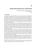
Validation of Life-Prediction Algorithms and Their Application. The overall comparison between the observed
and theoretical crack-propagation rates in type 304/316 stainless steels in 288 °C water is shown in Fig. 41. The
laboratory database upon which this comparison was made was obtained under a wide range of stressing (static,
monotonically increasing, and cyclic load), material (solution annealed vs. various degrees of sensitization) and water
composition (<10 ppb O
2
to >8 ppm O
2
, <0.1 to 10 S · cm
-1
). It is seen that there is a reasonable agreement between
observation and prediction.
Fig. 41 Comparisons between observed and theoretical crack-
propagation rates for type 304/316 stainless
steels in 288 °C water. This database represents a wide combination of stressing material and environmental
conditions. Source: Ref 96
Changes in corrosion potential within the range expected in BWRs can have a significant effect on the cracking
susceptibility of type 304/316 stainless steels, especially under constant-load conditions. This predicted and observed
effect is illustrated in Fig. 42 for furnace-sensitized type 304 stainless steel under constant stress intensity (25 ksi )
in water with the conductivity in the range 0.1 to 0.3 S · cm
-1
. It is seen that over the corrosion potential range -550
mV
SHE
to +250 mV
SHE
(spanning "hydrogen-water" conditions to those under "normal" core conditions) the crack-
propagation rate can change three orders of magnitude. From an operational design viewpoint, therefore, it is seen that
considerable benefit may be predicted by developing actions that lower the corrosion potential of the stainless steel
structures, thereby highlighting remedial actions that lower the effective concentration of oxidants (oxygen, hydrogen
peroxide) in the coolant. Solution conductivity is also predicted to have an effect on the cracking susceptibility, as
indicated by the three theoretical relationships shown in Fig. 42, thereby highlighting the quantitative value of
maintaining water-purity control.
Fig. 42 Observed and predicted sensitivity of stress-corrosion-
cracking sensitivity to corrosion potential for
sensitized type 304 stainless steel in 288 °C water. The data points are measurements made in the laboratory
or in reactors. The curves are the predicted relationships for the indicated
conductivities. The numbered data
points were obtained at the Harwell variable-
energy cyclotron. The circled numbers were with the proton
irradiation turned on, and the uncircled numbers were with the irradiation off. Similarly the data point * was
obtained under fast neutron irradiation in a boiling-water-reactor core.
So far, the comparisons between observation and theory have centered on material/environment systems variables that
affect n in Eq 25 and 26. The effect of stressing/straining conditions on the cracking susceptibility occur primarily
through their effect on the crack-tip strain rate in Eq 27, 28, and 29. It follows that because the crack tip does not
recognize how the strain rate is maintained, the cracking susceptibility for a given material/environment condition should
adhere to the same crack-propagation rate/crack-tip strain-rate relationship, regardless of the stressing/straining mode.
The truth to this statement is illustrated in Fig. 43, which shows the theoretical and observed crack-propagation rate
strain-rate relationship for a severely sensitized type 304 stainless steel in 8 ppm O
2
, 0.5 S · cm
-1
water. Movement along
the strain-rate axis has been achieved by increasing stress intensity under constant-load conditions, increasing applied
strain rate under monotonically increasing strain conditions, or cyclic loading under a variety of stress-intensity
amplitude, mean stress, and loading frequency conditions. The single theoretical relationship line in Fig. 43 adequately
predicts the cracking under this wide range of loading modes, indicating that the prediction method applies to stress-
corrosion cracking (SCC), strain-induced cracking (SIC), and corrosion fatigue (CF).
Fig. 43 Predicted and observed crack-propagation rate/crack-tip strain-
rate relationships for sensitized type
304 stainless steel in 8 ppm oxygenated, 0.5 S · cm
-1
purity water at 288 °C
The old lore that these types of cracking (SCC, SIC, CF) are separate phenomena with, by implication, different
mitigation or design modification needs is probably incorrect. For instance, it follows from Eq 25 that the sensitivity of
the cracking susceptibility to the crack-tip strain rate will be a function of the material/environment conditions that affect
n (Eq 26). Thus, the slope of the crack-propagation-rate/strain-rate relationship will be relatively shallow for severe
environmental and material conditions (e.g., high dissolved oxygen, impure water, and high degrees of grain-boundary
sensitization), and the relationship will be steep for less severe material/environmental conditions. This predicted and
observed (Fig. 44) change in propagation-rate/strain-rate dependency with system conditions is significant when
evaluating the validity of accelerated tests that are often used for development of design codes. For instance, increasing
the crack-tip strain rate, and hence cracking susceptibility, by using the "slow-strain-rate test" is a valid test acceleration
procedure (because it is accelerating one of the rate-determining steps in the cracking mechanism), but the factor of
improvement between a reference condition and a proposed mitigation condition will be less in this test than at the lower
stressing or strain-rate conditions expected in the operating plant. The relationship (i.e., Fig. 44) also gives an explanation
for the lore that the cracking susceptibility is more dependent on the specific environmental conditions under constant-
load stress-corrosion conditions than under corrosion-fatigue conditions.
Fig. 44 Predicted and observed crack-propagation rate/crack-tip strain-
rate relationships for stainless steels in
a variety of material/environment systems
In summary, therefore, it is apparent that the crack-prediction algorithms are able to quantitatively explain the changes in
crack-propagation rates for type 304/316 stainless steel in water at 288 °C for a wide combination of water composition
(corrosion, potential, conductivity), material sensitization, and stressing (constant load/displacement, cyclic load)
conditions. It follows, however, that because the cracking response is so sensitive to changes in combinations of system
conditions, it is necessary to combine the predictive method with system-defining sensors and models (Fig. 45). Provided
this combining is done, it is then possible to make predictions of the extent of cracking in specific plant components (Fig.
46) and the increase in life associated with specific system changes (Fig. 47).
Fig. 45 The integration of system monitors, sensors, and environmental/material models as inputs to a crack-
propagation-rate model
Fig. 46 Theoretical and observed intergranular stress corrosion crackdepth vs. operational-
time relationships
for 28 in. diameter schedule 80 type 304 stainless steel piping for two boiling-
water reactors operating at
different mean coolant conductivities. Note the bracketing of the maximum crack depth in the lower-
purity
plant by the predicted curve, which is based on the maximum residual-
stress profile and the predicted absence
of observable cracking in the higher-purity plant (in 240 operating months).
Fig. 47
Predicted crack depth vs. time response for defected 28 in. diameter schedule 80 recirculation piping in
a given boiling-water reactor to defined changes in water purity. Also shown is the crack-
depth limit that can be
resolved by nondestructive testing (NDT).
References cited in this section
10. M.G. Fontana, Corrosion Engineering, 3rd ed., McGraw-Hill Book Co., 1986
81. R.L. Jones, "Corrosion Experience in U.S. Light Water Reactors NACE
50th Anniversary Perspective,"
Paper 168, presented at Corrosion 93, NACE, 1993
82.
R.L. Jones, "Critical Corrosion Issues and Mitigation Strategies Impacting the Operability of LWRs,"
Paper 103, presented at Corrosion 96, NACE, 1996
83. Conf. Proc., Environmental Degradation of Materials in Nuclear Systems Light Water Reactors,
J.
Roberts and W. Berry, Ed., NACE, 1983
84. Conf. Proc., Environmental Degradation of Materials in Nuclear Systems Light Water Reactors,
J.
Roberts and J. Weeks, Ed., ANS, 1985
85. Conf. Proc., Environmental Degradation of Materials in Nuclear Systems Light Water Reactors,
J. Weeks
and G. Theus, Ed., TMS, 1987
86. Conf. Proc., Environmental Degradation of Materials in Nuclear Systems Light Water Reactors,
G.
Theus and D. Cubicciotti, Ed., NACE, 1989
87. Conf. Proc., Environmental Degradation of Materials in Nuclear Systems Light Water Reactors,
D.
Cubicciotti and E. Simonen, Ed., ANS, 1991
88. Conf. Proc., Environmental Degradation of Materials in Nuclear Systems Light Water Reactors,
R. Gold
and E. Simonen, Ed., TMS, 1993
89. Conf. Proc., Environmental Degradation of Materials in Nuclear Systems Light Water Reactors,
R. Gold
and E. McIlree, Ed., NACE, 1995
90. H. Okada and R. Staehle, Ed., Predictive Methods for Asse
ssing Corrosion Damage to BWR Piping and
PWR Steam Generators, NACE, 1982
91. D.D. MacDonald and G.A. Cragnolino, Corrosion of Steam Cycle Materials,
ASME Handbook on Water
Technology for Thermal Power Systems, P. Cohen, Ed., ASME, 1979
92. J.T.A. Roberts, Structural Materials in Nuclear Power Systems, Plenum Press, 1981
93. J.C. Danko, Corrosion in the Nuclear Power Industry, Corrosion, Vol 13, ASM Handbook,
ASM
International, 1987
94. D.A. Hale, C.W. Jewett, and C.S. O'Toole, "BWR Coolant Impurities P
rogram," First Annual Progress
Report, Report NP2293, EPRI, Nov 1985
95.
W.S. Hazelton, "Technical Report on Materials Selection and Processing Guidelines for BWR Coolant
Pressure Boundary Piping," Draft report NUREG 0313 Rev. 2, U.S. Nuclear Regulatory C
ommission,
1978
96.
F.P. Ford, D.F. Taylor, P.L. Andresen, and R.G. Ballinger, "Corrosion Assisted Cracking of Stainless Steel
and Low Alloy Steels in LWR Environments," Report NP5064S, EPRI, Feb 1987
97. P.L. Andresen, Corrosion 47, NACE, 1991, p 917-938
99. F.P. Ford, P.L. Andresen, M.G. Benz, and D. Weinstein, On-
Line BWR Materials Monitoring and Plant
Component Lifetime Prediction, Proc. Nuclear Power Plant Life Extension,
American Nuclear Society,
Vol 1, June 1988, p 355-366
100.
F.P. Ford, "Mechan
isms of Environmental Cracking Peculiar to the Power Generation Industry," Report
NP2589, EPRI, Sept 1982
101.
F.P. Ford, Stress Corrosion Cracking, Corrosion Processes, R.N. Parkins, Ed., Applied Science, 1982
102.
F.P. Ford, The Crack Tip System and it
s Relevance to the Prediction of Environmentally Assisted
Cracking, Proc. First International Conf. Environment Induced Cracking of Metals,
NACE, Oct 1988, p
139-166
103.
R.N. Parkins, Environment Sensitive Fracture Controlling Parameters, Proc. Third In
ternational Conf.
Mechanical Behavior of Materials, K.J. Miller and R.F. Smith, Ed., Pergamon, Vol 1, 1980, p 139-164
104.
T.R. Beck, Corrosion 30, NACE, 1974, p 408
105.
J. Hickling, "Strain Induced Corrosion Cracking: Relationship to Stress Corrosion C
racking/Corrosion
Fatigue and Importance for Nuclear Plant Service Life, paper presented at Third IAEA Specialists Meeting
on Subcritical Crack Growth, Moscow, May 1990
Design for Corrosion Resistance
F. Peter Ford and Peter L. Andresen, General Electric Corporate Research and Development Center; Peter Elliott, Corrosion and
Materials Consultancy, Inc.
References
1. H. Uhlig, Chemical and Engineering News, Vol 97, 1949, p 2764
2. Editorial, Corrosion Prevention and Control, Vol 27, 1980, p 1
3. T.P. Hoar, Report of the Committee on Corrosion and Protection,
Her Majesty's Stationery Office,
London, 1971
4. Proc. 1986 Joint Chinese-American Corrosion Workshop,
Industrial Technology Research Institute,
Hsinchu, Taiwan, Dec 1986
5. D.A. Jones, Principles and Prevention of Corrosion, 2nd ed., Prentice Hall, 1996
6. K.R. Trethewey and J. Chamberlain, Corrosion for Science and Engineering, 2nd ed., Longman, 1995
7. P. Marcus and J. Oudar, Corrosion Mechanisms in Theory and Practice, Marcel Dekker, Inc., 1995
8. C.P. Dillon, Corrosion Resistance of Stainless Steels, Marcel Dekker, Inc., 1995
9. B.D. Craig, Fundamental Aspects of Corrosion Films in Corrosion Science, Plenum Press, 1991
10. M.G. Fontana, Corrosion Engineering, 3rd ed., McGraw-Hill Book Co., 1986
11. W.W. Kirk and H.H. Lawson, Atmospheric Corrosion, ASTM, 1995
12. J.C. Scully, The Fundamentals of Corrosion, Pergamon Press, 1975
13. H.P. Hack, Galvanic Corrosion, ASTM, 1988
14. S.L. Chawla and R.K. Gupta, Materials Selection for Corrosion Control, ASM International, 1993
15. P.A. Schweitzer, Corrosion and Corrosion Protection Handbook, 2nd ed., Marcel Dekker, 1989
16. G. Moran and P. Labine,
Corrosion Monitoring in Industrial Plants Using Nondestructive Testing and
Electrochemical Methods, ASTM, 1986
17. D.O. Northwood, W.E. White, and G.F. Vander Voort, Corrosion, Microstructure, and Metallography,
American Society for Metals, 1985
18. R.S. Treseder, R. Baboian, and C.G. Munger, Ed., NACE Corrosion Engineer's Reference Book,
2nd ed.,
NACE, 1991
19. R.B. Seymour, Plastics vs. Corrosives, John Wiley & Sons, 1982
20. M. Henthorne, Localized Corrosion Cause of Metal Failure, ASTM, 1972
21. R. Baboian, Electrochemical Techniques for Corrosion Engineering, NACE, 1985
22. Corrosion, Vol 13, ASM Handbook (formerly Metals Handbook, 9th ed.), ASM International, 1987
23. S.K. Coburn, Corrosion Source Book, American Society for Metals, 1984
24. A.J. McEvily, Jr., Atlas of Stress-Corrosion and Corrosion Fatigue Curves, ASM International, 1990
25. L.L. Shreir, R.A. Jaman, and G.T. Burstein, Corrosion Metal/Environment Reactions,
Butterworth
Heinenmann, Ltd., 1994
26. R.F. Steigerwald and N.D. Greene, J. Electrochem. Soc., Vol 109, 1962, p 1026
27. H.H. Uhlig and R.W. Rene, Corrosion and Corrosion Control, 3rd ed., John Wiley & Sons, 1985, p 217
28. Z. Szklarska-Smialawska, Pitting Corrosion of Metals, NACE, 1986
29.
F.P. Ford, "Mechanisms of Environmental Cracking Peculiar to the Power Generation Industry," Report
NP2589, EPRI, 1982
30. F.P. Ford, Stress Corrosion Cracking, Corrosion Processes, R.N. Parkins, Ed., Applied Science, 1982
31. R.N. Parkins, N.J.H. Holroyd, and R.R. Fessler, Corrosion, Vol 34, 1978, p 253
32. B. Poulson and R. Robinson, Corr. Sci., Vol 20, 1980, p 707
33. J. Congl
eton, "Some Aspects of Crack Initiation in Stress Corrosion and Corrosion Fatigue," paper
presented at Corrosion 88, NACE, St. Louis, 21-25 March 1988
34. Conf. Proc., Environmental-Sensitive Mechanical Behavior
(Baltimore, MD, June 1965), A.R.C.
Westwood and N.S. Stoloff, Ed., Gordon and Breach, 1966
35. R.W. Staehle, A.J. Forty, and D. Van Rooyen, Ed., The Fundamental Aspects of Stress-
Corrosion
Cracking, Ohio State University, Sept 1967
36. J.C. Scully, Ed., Theory of Stress Corrosion Cracking, NATO, Brussels, March 1971
37. O. Devereaux, A.J. McEvily, and R.W. Staehle, Ed.,
Corrosion Fatigue Chemistry, Mechanics and
Microstructure, University of Connecticut, Storrs, June 1971
38. M.P. Bastein, Ed., L'Hydrogene dans les Metaux, Science et Industrie, Paris, 1972
39. L.M. Bernstein and A.W. Thompson, Ed., Hydrogen in Metals, L, American Society for Metals, 1973
40. R.W. Staehle, J. Hochmann, R.D. McCright, and J.E. Slater, Ed., Stress-
Corrosion Cracking and Hydrogen
Embrittlement of Iron-Base Alloys, NACE, 1977
41. A.W. Thompson and I.M. Bernstein, Ed., Proc. Effect of Hydrogen on Behavior of Materials
(Jackson
Lake, WY, Sept 1975), TMS, 1976
42. R.M. Latanision and J.T. Fourie, Ed., Surface Effects on Crystal Plasticity
(Hohegeiss, Germany, 1975),
Noordhof-Leyden, 1977
43. P.R. Swann, F.P. Ford, and A.R.C. Westwood, Ed.,
Mechanisms of Environment Sensitive Cracking of
Materials, The Metals Society, April 1977
44. Corrosion Fatigue, Met. Sci., Vol 13, 1979
45. T.R. Beck, Corrosion, Vol 30, 1974, p 408
46. R.W. Staehle, in Theory of Stress Corrosion Cracking, J.C. Scully, Ed., NATO, Brussels, March 1971
47. J.C. Scully, Corros. Sci., Vol 8, 1968, p 771
48. D.J. Lees, F.P. Ford, and T.P. Hoar, Met. Mater., Vol 7, 1973, p 5
49. J.R. Ambrose and J. Kruger, J. Electrochem. Soc., Vol 121, p 1974, p 599
50. F.P. Ford and M. Silverman, Corrosion, Vol 36, 1980, p 558
51. V.R. Pludek, Design and Corrosion Control, MacMillan, 1977
52. R.J. Landrum, Fundamentals of Designing for Corrosion Control, NACE International, 1989
53. R.N. Parkins and K.A. Chandler, Corrosion Control in Engineering Design,
Department of Industry, Her
Majesty's Stationery Office, London, 1978
54. L.D. Perrigo and G.A. Jensen, Fundamentals of Corrosion Control Design, The Northern Engineer,
Vol 13
(No. 4), 1982, p 16
55. Designer Handbooks,
Specialty Steel Industry of North America, Washington, D.C.; also publications
relative to design, Nickel Development Institute, Toronto, Canada
56. Guides to Practice in Corrosion Control, Dep
artment of Industry, Her Majesty's Stationery Office,
London, 1979-1986
57. Engineering Design Guides,
Design Council, British Standards Institute, Council of Engineering
Institutions, Oxford University Press, 1975-1979
58. P. Elliott and J.S. Llewyn-Leach, Corrosion Control Checklist for Design Offices,
Department of Industry,
Her Majesty's Stationery Office, London, 1981
59. P. Elliott, Corrosion Control in Engineering Design,
audiovisual for Department of Industry, United
Kingdom, 1981
60. O.W. Siebert, Classic Blunders in Corrosion Protection, Mater. Perform.,
Vol 17 (No. 4), 1978, p 33 and
Vol 22 (No. 10), 1983
61. T.F. Degnan, Mater. Perform. Vol 26 (No. 1), 1987, p 11
62. P. Elliott, Why Must History Repeat Itself?, Ind. Corros., Feb/March 1991, p 8
63. P. Elliott, Process Plant Corrosion Recognizing the Threat, Process Eng., Vol 65 (No. 11), 1984, p 43
64. P. Elliott, Understanding Corrosion Attack, Plant Eng., Oct 1993, p 68
65. P. Elliott, Corrosion Survey, Supplement to Chem. Eng., Sept 1973
66. P. Elliott, Catch 22 and the UCS Factor Why Must History Repeat Itself?, Mater. Perform.,
Vol 28 (No.
7), 1989, p 70 and Vol 28 (No. 8), 1989, p 75
67. Standards for Corrosion Testing of Metals, ASTM, 1990
68. R. Baboian, Ed., Corrosion Tests and Standards: Applications and Interpretation,
ASTM Manual Series,
MNL-20, 1995
69. H.J.H. Wassell, Reliability of Engineered Products,
Engineering Design Guide, Design Council, Oxford
University, 1980
70. P. Elliott, We Never get Corrosion Problems, Super News, 1974, p 70
71. A. Sparks, Steel Carriage by Sea, 2nd ed., Lloyd's of London Press, 1995
72. G. Kobrin, Ed., Microbiologically Influenced Corrosion, NACE International, 1993
73. P. Elliott, Practical Guide to High Temperature Alloys, Mater. Perform., Vol 28, 1989, p 57
74. G.Y. Lai, High Temperature Corrosion of Engineering Alloys, ASM International, 1990
75. W. Pollock, Corrosion under Wet Insulation, NACE International, 1988
76. "Specification for Wicking-Type Thermal Insulation for Use Ove
r Austenitic Stainless Steel," C 795,
Annual Book of ASTM Standards, ASTM
77.
"Codes of Practice for Drinking Water Installations (TRWI)," 628.1.033:696.11:620.193, DIN, Teil 7,
1988
78. H.H. Uhlig, Corrosion and Corrosion Control, 2nd ed., John Wiley & Sons, 1971, p 314
79. C.G. Munger, Corrosion Prevention by Protective Coatings, NACE International, 1984
80. P.E. Weaver, "Industrial Maintenance Painting," RP0178, NACE International, 1973, p 2
81. R.L. Jones, "Corrosion Experience in U.S. Light Water Reactors
NACE 50th Anniversary Perspective,"
Paper 168, presented at Corrosion 93, NACE, 1993
82.
R.L. Jones, "Critical Corrosion Issues and Mitigation Strategies Impacting the Operability of LWRs,"
Paper 103, presented at Corrosion 96, NACE, 1996
83. Conf. Proc., Environmental Degradation of Materials in Nuclear Systems Light Water Reactors,
J.
Roberts and W. Berry, Ed., NACE, 1983
84. Conf. Proc., Environmental Degradation of Materials in Nuclear Systems Light Water Reactors,
J.
Roberts and J. Weeks, Ed., ANS, 1985
85. Conf. Proc., Environmental Degradation of Materials in Nuclear Systems Light Water Reactors,
J. Weeks
and G. Theus, Ed., TMS, 1987
86. Conf. Proc., Environmental Degradation of Materials in Nuclear Systems Light Water Reactors,
G.
Theus and D. Cubicciotti, Ed., NACE, 1989
87. Conf. Proc., Environmental Degradation of Materials in Nuclear Systems Light Water Reactors,
D.
Cubicciotti and E. Simonen, Ed., ANS, 1991
88. Conf. Proc., Environmental Degradation of Materials in Nuclear Systems Light Water Reactors,
R. Gold
and E. Simonen, Ed., TMS, 1993
89. Conf. Proc., Environmental Degradation of Materials in Nuclear Systems Light Water Reactors,
R. Gold
and E. McIlree, Ed., NACE, 1995
90. H. Okada and R. Staehle, Ed., Predictive Me
thods for Assessing Corrosion Damage to BWR Piping and
PWR Steam Generators, NACE, 1982
91. D.D. MacDonald and G.A. Cragnolino, Corrosion of Steam Cycle Materials,
ASME Handbook on Water
Technology for Thermal Power Systems, P. Cohen, Ed., ASME, 1979
92. J.T.A. Roberts, Structural Materials in Nuclear Power Systems, Plenum Press, 1981
93. J.C. Danko, Corrosion in the Nuclear Power Industry, Corrosion, Vol 13, ASM Handbook,
ASM
International, 1987
94. D.A. Hale, C.W. Jewett, and C.S. O'Toole, "BWR Coolan
t Impurities Program," First Annual Progress
Report, Report NP2293, EPRI, Nov 1985
95.
W.S. Hazelton, "Technical Report on Materials Selection and Processing Guidelines for BWR Coolant
Pressure Boundary Piping," Draft report NUREG 0313 Rev. 2, U.S. Nuclea
r Regulatory Commission,
1978
96.
F.P. Ford, D.F. Taylor, P.L. Andresen, and R.G. Ballinger, "Corrosion Assisted Cracking of Stainless Steel
and Low Alloy Steels in LWR Environments," Report NP5064S, EPRI, Feb 1987
97. P.L. Andresen, Corrosion 47, NACE, 1991, p 917-938
98. F.P. Ford, "Environmentally Assisted Cracking of Low Alloy Steels," Final Report of Contract C102-
1,
Report NP7473-L, EPRI, Jan 1992
99. F.P. Ford, P.L. Andresen, M.G. Benz, and D. Weinstein, On-Line BWR Materials Monitoring and Plant
Component Lifetime Prediction, Proc. Nuclear Power Plant Life Extension,
American Nuclear Society,
Vol 1, June 1988, p 355-366
100.
F.P. Ford, "Mechanisms of Environmental Cracking Peculiar to the Power Generation Industry," Report
NP2589, EPRI, Sept 1982
101.
F.P. Ford, Stress Corrosion Cracking, Corrosion Processes, R.N. Parkins, Ed., Applied Science, 1982
102.
F.P. Ford, The Crack Tip System and its Relevance to the Prediction of Environmentally Assisted
Cracking, Proc. First International Conf. Environment Induced Cracking of Metals,
NACE, Oct 1988, p
139-166
103.
R.N. Parkins, Environment Sensitive Fracture Controlling Parameters,
Proc. Third International Conf.
Mechanical Behavior of Materials, K.J. Miller and R.F. Smith, Ed., Pergamon, Vol 1, 1980, p 139-164
104.
T.R. Beck, Corrosion 30, NACE, 1974, p 408
105.
J. Hickling, "Strain Induced Corrosion Cracking: Relationship to Stress Corrosion Cracking/Corrosion
Fatigue and Importance for Nuclear Plant Service Life, paper presented at Third IAEA S
pecialists Meeting
on Subcritical Crack Growth, Moscow, May 1990
106.
K. Osozaawa and H.J. Engell, Corros. Sci., Vol 6, 1966, p 389
Design for Corrosion Resistance
F. Peter Ford and Peter L. Andresen, General Electric Corporate Research and Development Center; Peter Elliott, Corrosion and
Materials Consultancy, Inc.
Selected References
*
• V.A. Ashworth and P. Elliot, Guide to the Corrosion Resistance of Metals, Metals Reference Book,
5th ed., C.J. Smithells and E.A. Brandes, Ed., Butterworths, 1976, p 1460
• B.D. Craig and D. Anderson, Ed., Handbook of Corrosion Data, 2nd ed., ASM International, 1995
• Corrosion Data Survey: Metals Section, 6th ed., NACE, 1985
• Corrosion Data Survey: Nonmetals Section, 5th ed., NACE, 1975
• D.J. De Renzo, Ed., Corrosion-Resistant Materials Handbook, 4th ed., Noyes, 1985
• DECHEMA Corrosion Handbook: Corrosive Agents and Their Interaction with Materials,
D.
Behrens (Vol 1-9) and G. Kreysa and R. Eckermann (Vol 10-12), Ed., VCH, 1987-1993
• NACE/NIST Corrosion Performance Databases,
Corrosion Data Center, National Institute of
Standards and Technology, Gaithersburg, MD
• P.A. Schweitzer, Ed., Corrosion Resistance Tables, 3 vol, 4th ed., Marcel Dekker, 1995
• H.H. Uhlig, Corrosion Handbook, John Wiley & Sons, 1948
• H.H. Uhlig and R.W. Revie,
Corrosion and Corrosion Control: An Introduction to Corrosion
Science and Engineering, 3rd ed., Wiley, 1985
References cited in this section
5. D.A. Jones, Principles and Prevention of Corrosion, 2nd ed., Prentice Hall, 1996
6. K.R. Trethewey and J. Chamberlain, Corrosion for Science and Engineering, 2nd ed., Longman, 1995
7. P. Marcus and J. Oudar, Corrosion Mechanisms in Theory and Practice, Marcel Dekker, Inc., 1995
8. C.P. Dillon, Corrosion Resistance of Stainless Steels, Marcel Dekker, Inc., 1995
9. B.D. Craig, Fundamental Aspects of Corrosion Films in Corrosion Science, Plenum Press, 1991
10.
M.G. Fontana, Corrosion Engineering, 3rd ed., McGraw-Hill Book Co., 1986
11.
W.W. Kirk and H.H. Lawson, Atmospheric Corrosion, ASTM, 1995
12.
J.C. Scully, The Fundamentals of Corrosion, Pergamon Press, 1975
13.
H.P. Hack, Galvanic Corrosion, ASTM, 1988
14.
S.L. Chawla and R.K. Gupta, Materials Selection for Corrosion Control, ASM International, 1993
15.
P.A. Schweitzer, Corrosion and Corrosion Protection Handbook, 2nd ed., Marcel Dekker, 1989
16.
G. Moran and P. Labine, Corrosion Monitorin
g in Industrial Plants Using Nondestructive Testing and
Electrochemical Methods, ASTM, 1986
17.
D.O. Northwood, W.E. White, and G.F. Vander Voort, Corrosion, Microstructure, and Metallography,
American Society for Metals, 1985
18.
R.S. Treseder, R. Baboian, and C.G. Munger, Ed., NACE Corrosion Engineer's Reference Book,
2nd ed.,
NACE, 1991
19.
R.B. Seymour, Plastics vs. Corrosives, John Wiley & Sons, 1982
20.
M. Henthorne, Localized Corrosion Cause of Metal Failure, ASTM, 1972
21.
R. Baboian, Electrochemical Techniques for Corrosion Engineering, NACE, 1985
22.
Corrosion, Vol 13, ASM Handbook (formerly Metals Handbook, 9th ed.), ASM International, 1987
23.
S.K. Coburn, Corrosion Source Book, American Society for Metals, 1984
24.
A.J. McEvily, Jr., Atlas of Stress-Corrosion and Corrosion Fatigue Curves, ASM International, 1990
25.
L.L. Shreir, R.A. Jaman, and G.T. Burstein, Corrosion Metal/Environment Reactions,
Butterworth
Heinenmann, Ltd., 1994
26.
R.F. Steigerwald and N.D. Greene, J. Electrochem. Soc., Vol 109, 1962, p 1026
27.
H.H. Uhlig and R.W. Rene, Corrosion and Corrosion Control, 3rd ed., John Wiley & Sons, 1985, p 217
28.
Z. Szklarska-Smialawska, Pitting Corrosion of Metals, NACE, 1986
68.
R. Baboian, Ed., Corrosion Tests and Standards: Applications and Interpretation,
ASTM Manual Series,
MNL-20, 1995
79.
C.G. Munger, Corrosion Prevention by Protective Coatings, NACE International, 1984
Note cited in this section
* See also Ref 5, 6, 7, 8, 9, 10, 11, 12, 13, 14, 15, 16, 17, 18, 19, 20, 21, 22, 23, 24, 25, 26, 27, 28
,
68, and 79 in the list of numbered references.
Design for High-Temperature
Applications
David A. Woodford, Materials Performance Analysis, Inc.
Introduction
APART FROM nineteenth-century steam boilers, machines and equipment for high-temperature operation have been
developed principally in the present century. Energy conversion systems based on steam turbines, gas turbines, high-
performance automobile engines, and jet engines provide the technological foundation for modern society. All of these
machines have in common the use of metallic materials at temperatures where time-dependent deformation and fracture
processes must be considered in their design. The single valued time-invariant strain associated with elastic or plastic
design analysis in low-temperature applications is not applicable, nor is there in most situations a unique value of fracture
toughness that may be used as a limiting condition for part failure. In addition to the phenomenological complexities of
time-dependent behavior, there is now convincing evidence that the synergism associated with gaseous environmental
interactions may have a major effect, in particular on high-temperature fracture.
This article reviews the basic mechanisms of elevated-temperature behavior and associated design considerations with
emphasis on metals. Subsequently, the engineering analysis will be confined to presenting data in the form that a designer
might use, with emphasis on design principles rather than detailed design analysis. Thus, multiaxial stresses, part analysis,
and creep-fatigue interaction are not formally treated. However, remaining life assessment and the effect of nonsteady
stresses are covered. A broader treatment of most of these aspects can be found in other articles that appear in the ASM
Specialty Handbook: Heat-Resistant Materials and in Mechanical Testing, Volume 8 of the ASM Handbook. Emphasis
here is placed on developing an appreciation of the uses (and abuses) of creep and rupture testing, data presentation, data
analysis, limitations of long-time tests, and alternative approaches to high-temperature design. The objective is to provide
a solid foundation for design principles from a materials performance perspective.
Acknowledgements
Of all the people who have influenced his thinking over the years, the author would like to give special thanks to the late
Robert Goldhoff, who directed him into this field of study and research; Louis Coffin, who has provided direct and
indirect influence over the years; Edward Hart, a rigorous thinker and writer; Roger Bricknell, an intellectual partner;
Michael Henry, a creative materials engineer; the late Chester Sims, a force in superalloys; Joanne Beckman, his first
Ph.D. student; Donald Van Steele, an outstanding experimentalist; and David Stiles, a supporter of new ideas.
Design for High-Temperature Applications
David A. Woodford, Materials Performance Analysis, Inc.
Historical Development of Creep Deformation Analysis
The phenomenon of time-dependent deformation was referred to as slow stretch by Philips (Ref 1) and as viscous flow by
Andrade (Ref 2) at the beginning of this century and subsequently became known as creep. There were several seminal
ideas in the Andrade work that have had a lasting impact on scientific studies and engineering dogma. The initial work
was primarily on lead wires at room temperature (a high temperature relative to the melting point for lead) with some
additional experiments on a 78.5% Sn 21.5% Pb alloy and copper. Andrade noted that after applying a fixed load the rate
of extension initially decreased then became constant for a time, but finally increased and continued increasing until
failure. He recognized that as the wire stretched, the load per unit area increased. Subsequently, he devised a scheme to
compensate for this and maintain a constant stress on the wire. As a result of this, the extent of viscous flow, that is,
extension linearly dependent on time, increased as shown in Fig. 1. Andrade also recognized that the length of wire being
experimented on at any time is increasing and thus used the concept of true strain. He derived a formula to describe the
observed deformation:
1 = l
o
(1 + t
1/3
)e
kt
(Eq 1)
where l and l
o
are the current and initial specimen lengths, t is the time, and and k are constants. The initial transient
strain (later to be called primary creep) was referred to as beta creep and followed a time to the one-third law, the viscous
region (later to be called steady-state creep) was proportional to time, and the accelerating strain region leading to
fracture, which was not specifically treated by Andrade, later became known as tertiary creep. Much later, in a
comprehensive study of creep in copper and aluminum, Wyatt (Ref 3) concluded that there are two types of transient
creep in metals:
• At higher temperatures, beta creep predominates as in Andrade's experiments.
• At lower temperatures, the strain is proportional to log(time), and the flow is referred to as alpha creep.
Fig. 1 Creep tests on lead wire. In both tests, initial lengths and initial loads were the same. Source: Ref 2
From this early work, subsequent studies diverged into two investigative paths. The first sought understanding of creep
deformation micromechanisms in pure metals and solid-solution alloys in relatively short-term tests, accepted the concept
of steady-state creep (although testing was more often conducted at constant load rather than constant stress), and often
assumed implicitly that viscous flow was history independent. This means that not only is there a steady creep rate
associated with a given applied stress, but that this rate is obtained despite previous deformation at different stresses and
temperatures. Although this might be a reasonable approximation for pure metals, it is manifestly wrong for most
engineering alloys.
The second investigative path concentrated on generating long-time creep data on engineering materials. The testing was
invariably at constant load, and data extracted included times for specific creep strains, minimum creep rates (although
the term steady state was often used despite the fact that constant rates cannot be expected when the stress is changing),
and time to failure (often referred to as rupture life). This latter measurement was of special significance because it
became a basis for design against part failure, and later as a basis for estimating remaining life of operating components.
There thus emerged a framework for design against both creep deformation and fracture using a single testing procedure.
It formed a basis for what might be called an uncracked body analysis and comprises the major part of this article.
Analysis of cracked bodies involving fracture mechanics concepts as applied to creeping structures is not covered
although some reference is made as appropriate. In particular, the importance of fatigue loading is emphasized in the
article "Creep-Fatigue Interaction" in the ASM Specialty Handbook: Heat-Resistant Materials.
Until the last quarter century, virtually all creep and creep fracture studies were on metallic materials. However, as early
as 1903, Philips (Ref 1) recognized that the phenomenon was not unique to the metallic bond and that materials with
covalent and ionic bonds showed similar effects. In fact, creep of polymers is now of considerable importance in plastic
automobile components and gas lines, and creep of ceramics is of interest in aerospace applications.
References cited in this section
1.
F. Philips, The Slow Stretch in India Rubber, Glass and Metal Wire When Subjected to a Constant Pull,
Philos. Mag., Vol 9, 1905, p 513
2.
E.N. da C. Andrade, The Viscous Flow in Metals and Allied Phenomena, Proc. R. Soc., Vol A84, 1910, p 1-
13
3.
O.H. Wyatt, Transient Creep in Pure Metals, Proc. Phys. Soc., Vol 66B, 1953, p 459-480
Design for High-Temperature Applications
David A. Woodford, Materials Performance Analysis, Inc.
Basic Concepts of Elevated-Temperature Design
Time-dependent deformation and fracture of structural materials at elevated temperatures are among the most challenging
engineering problems faced by materials engineers. In order to develop an improved design methodology for machines
and equipment operating at high temperatures, several key concepts and their synergism must be understood. As is
described in this section, these include:
• Plastic instability at elevated temperatures
• Deformation mechanisms and strain components associated with creep processes
• Stress and temperature dependence
• Fracture at elevated temperatures
• Environmental effects
Design Phenomenology
The issues of interest from a design basis are the nature of primary creep, the validity of the concept of viscous steady-
state creep, and the dependence of deformation on both temperature and stress. The simplest and most pervasive idea in
creep of metals is an approach to an equilibrium microstructural and mechanical state. Thus a hardening associated with
dislocation generation and interaction is countered by a dynamic microstructural recovery or softening. This process
proceeds during primary creep and culminates in a steady-state situation. The idea was first presented by Bailey (Ref 4)
and subsequently in the following mathematical form by Orowan (Ref 5):
(Eq 2)
where d represents the change in flow stress, / represents the hardening that results from an increment of plastic
strain d , and / t represents the softening due to recovery in a time increment dt.
At constant stress (and temperature), the steady-state creep rate is given by:
(Eq 3)
The numerator is frequently given the symbol r as the recovery rate associated with thermal softening, and the
denominator is referred to as the strain-hardening coefficient, h. Although there is evidence that both hardening and
softening processes occur during creep, and despite the fact that numerous studies have attempted to quantify Eq 2, it is in
fact incorrect. As pointed out by McCartney (Ref 6), Eq 2 implies that an equation of state exists of the form:
= ( ,t)
(Eq 4)
Equation 2 is the differential form of Eq 4, which assumes that the variables and t are independent. Since measured
strain is in fact a function of elapsed time t, it follows that the partial derivatives have no meaning. Lloyd and McElroy
(Ref 7) also concluded that the concept required a history-dependent term and the idea had serious deficiencies. They
further concluded that the related concept of the applied stress being the sum of an internal stress opposing dislocation
motion and an effective stress as the driving force for motion was inconsistent with real behavior. Their alternative theory
draws on the observation of anelastic phenomena, which is considered in a subsequent section.
The concept of steady-state creep has been addressed rigorously in very few publications (Ref 8). From these limited
studies, however, it can be stated that a constant creep rate cannot occur during the changing stress conditions of the
common constant load test (or, if the creep rate appears constant, it cannot be steady state). Further, it can be said that
most engineering alloys undergo purely time-dependent changes at temperature associated with an approach to
thermodynamic equilibrium, such as precipitate coarsening. With the additional complication of strain-induced changes, it
is unlikely that a steady state could be established. It is especially improbable that such a state could be history
independent. Any search for a true steady state should, therefore, be limited to pure metals or solid-solution alloys and
would require constant stress testing and true-strain plotting.
Plastic Instability
A major issue in the tensile creep test is the role of plastic instability in leading to tertiary creep. Understanding of the
nature of plastic instability for time-dependent flow has depended on the theory of Hart (Ref 9). He showed that the
condition for stable deformation is:
+ m 1
(Eq 5)
where m, which equals [( ln )/( ln )] , is the strain-rate sensitivity, and , which equals [( ln )/( )] , is a
measure of the strain-hardening rate. For steady-state flow, is equal to 0. For constant stress tests, Burke and Nix (Ref
10) concluded that flow must be unstable when steady state is reached according to Hart's criterion but that macroscopic
necking is insignificant and that the flow remains essentially homogeneous. They concluded that a true steady state does
exist. Hart himself questioned the conclusions based on their analysis but did not rule out the possibility of a steady state
for pure metals (Ref 8). In a very careful experimental analysis, Wray and Richmond (Ref 11) concluded that the concept
of a family of steady states is valid. They advocated tests in which two of the basic parameters (stress, strain rate, and
temperature) are held constant. However, they reported the intrusion of nonuniform deformation before the steady state
was reached. They also pointed out the complexities associated with uncontrolled and often unmeasured loading paths,
which produce different structures at the beginning of the constant stress or constant strain rate portions of the test. For
constant stress tests in pure metals, although the concept of steady state (viscous flow in Andrade's terminology) is
appealing, it appears not yet to have been rigorously demonstrated.
In constant load tests, steady-state behavior would of course result in an increasing creep rate after the minimum, as the
true stress increases. As such, the test is inappropriate to evaluate the concept. However, it is by far the most common
type of creep test and can be analyzed for instability (Ref 12). The condition for instability may be stated:
Ä 0
(Eq 6)
where Ä is the second derivative of specimen cross-sectional area with respect to time. This in turn leads to a point of
instability expressed in terms of gage length:
(Eq 7)
This criterion is shown in Fig. 2 for constant load tests on nickel. The instability criterion is fulfilled at a strain very close
to that of the minimum creep rate. However, the value of this criterion remains low up to 20 to 25% strain, at which
separate measurements of specimen profiles indicate that macroscopic necking occurs. In this respect, the results are
similar to constant stress results (Ref 10) in that although deformation is potentially unstable at the end of the primary
stage, it is not grossly so.
Fig. 2 Change in the parameter Ä/ with creep strain in nickel at
525 °C (980 °F) and 138 MPa (20 ksi).
Source: Ref 12
Creep Processes
Creep behavior can be characterized either in terms of deformation mechanisms or in terms of strain constituents.
Deformation Mechanisms. Creep of metals is primarily a result of the motion of dislocations, but is distinct from
time-independent behavior in that flow continues as obstacles, which may be dislocation tangles or precipitate particles,
are progressively overcome. The rate-controlling step involves diffusion to allow climb of edge dislocations or cross slip
of screw dislocations around obstacles. In steady-state theory, there is a balance between the hardening associated with
this dislocation motion and interaction, and a dynamic recovery associated with the development of a dislocation
substructure. Theory for such a process predicts a power-law dependence of creep rate on applied stress. For example,
climb-controlled dislocation creep gives an exponent n = 4 in the following equation (Ref 13):
= C
n
(Eq 8)
where C is a constant. Nothing in this or similar theories allows for history effects, and although the power function
connection may be applicable, the value of n is not only invariably higher, but strongly history dependent in structural
alloys (see the following section).
At very high homologous temperatures (T/T
m
) and low stresses, creep may occur in both metals and ceramics by mass
transport involving stress-directed flow of atoms from regions under compression to regions under tension. In this case,
theory indicates that there is a stress dependence of unity and that the process is controlled either by bulk diffusion (Ref
14, 15) or by grain-boundary diffusion (Ref 16). These various processes of creep (dislocation controlled as well as
diffusion controlled) may be represented on a deformation mechanism map to highlight regimes of stress and temperature
where each mechanism, based on current theories, may be operating (Ref 17). However, such maps are only as good as
the theories on which they are based and give no guidance on deformation path dependence.
Another important deformation process in metallic and ionic polycrystals at high temperature and low stresses is grain-
boundary sliding (Ref 18). The resistance to sliding is determined by the mobility of grain-boundary dislocations and by
the presence of hard particles at the boundary. This sliding leads to stress concentrations at grain junctions, which are
important in nucleating cracks. In ductile materials, these stress concentrations may be relieved by creep and stress
relaxation in the matrix or by grain-boundary migration (Ref 19).
Strain Components. There are several different sources of strain at high temperature in response to an applied stress.
The elastic strain is directly proportional to stress, and a modulus that is temperature dependent can be determined. For
metallic materials and ceramics, although there is a strain-rate dependence of elastic modulus, it is small and often
ignored. For polymers, by contrast, the elastic modulus is ill defined because of viscoelasticity.
Plastic strain for all materials may be treated as three separate constituents:
• Time-independent nonrecoverable, which may be thought of as an instantaneous deformation
• Time-de
pendent nonrecoverable, which may involve any or all of the micromechanisms described
above
• Time-dependent recoverable
The first of these is unlikely to be significant in practical applications except in the region of stress concentrations since
loading is normally well below the macroscopic yield stress. The second is the major source of creep in normal laboratory
testing. The third constituent is not widely studied or analyzed, but may become very important at low stresses and under
nonsteady conditions, that is, high-temperature service. It leads to what has been termed creep recovery and anelasticity.
At high temperatures, the application of a stress leads to creep deformation resulting from the motion of dislocations,
mass transport by diffusion, or grain-boundary sliding. These processes in turn lead to a distribution of internal stresses
that may relax on removal of the stress. This relaxation leads to a time-dependent contraction in addition to the elastic
contraction and results in the phenomenon of creep recovery illustrated in Fig. 3. In polymers this phenomenon, which
may account for nearly all the nonelastic strain, is termed viscoelastic recovery and is associated with the viscous sliding
and unkinking of long molecular chains (Ref 21). In metals it is associated with the unbowing of pinned dislocations (Ref
7), rearrangement of dislocation networks (Ref 22), and local grain-boundary motion (Ref 23). In ceramics it appears to
be primarily a grain-boundary phenomenon (Ref 24).
Fig. 3 Stress-time step applied to a material exhibiting strain response that includes time-
independent elastic,
time-independent plastic, time-dependent creep, and time-dependent anelastic (creep-
recovery) components.
Source: Ref 20
Whereas the importance of creep recovery is well recognized in polymer design, it has often been ignored in design of
metallic and ceramic materials. A few extensive studies have been reported on metals (Ref 25, 26, 27) that have led to
several broad conclusions:
• Creep-recovery strain increases linearly with stress for
a fixed time at a given temperature, but is
dependent on prestrain.
• The rate of creep recovery increases with increasing temperature.
• When the stress is low enough, essentially all transient creep is linear with stress and recoverable.
• Mathematically, t
he recovery may be described by a spectrum of spring dashpot combinations with a
wide range of relaxation times.
Assuming that the measured recovery strain after unloading had made an equivalent contribution to forward creep (Ref
28), it was possible in these studies to separate the anelastic and plastic creep components as shown in Fig. 4. Because the
anelastic component is linear with stress and the plastic component is a power function of stress (for the same time), at
very low stresses the strain is entirely anelastic. This observation led to the definition of a plastic creep limit that was time
dependent. For times up to 100 h in a low-alloy steel tested at 425 °C (800 °F), Lubahn (Ref 26) found this limit to be 140
MPa (20 ksi) (Ref 5); all creep below this stress was fully recoverable. In tests on a similar alloy at 538 °C (1000 °F),
Goldhoff (Ref 27) found that the creep limit ranged from 150 MPa (22 ksi) for 1 h to zero at 5000 h. By plotting the ratio
of anelastic to plastic strain for a fixed time (1000 h) as a function of stress (Fig. 5), Goldhoff (Ref 27) showed how the
former became dominant at low stresses. Figure 5 also shows that a heat treatment that produces low ductility leads to
higher ratios, suggesting a link between anelastic deformation and intergranular fracture, which was consistent with
microstructural observations of fracture in this alloy.
Fig. 4 The separation of strain components for a creep test on Cr-Mo-
V steel at 538 °C (1000 °F) and 35 MPa
(5 ksi). Source: Ref 27
Fig. 5 Effect of ductility on recoverable creep strain for Cr-Mo-V steel after 1000 h creep exposure. Source:
Ref
27
There have been even fewer systematic studies of creep recovery in ceramics, but silicon carbide fibers have been shown
to recover fully their creep strain between 1000 and 1400 °C (1830 and 2550 °F) (Ref 24). Additionally, provided an
appropriate period was allowed for recovery after each stress cycle, tension-tension fatigue resulted in zero cumulative
creep strain. This indicates the potential importance of anelastic phenomena in damage accumulation for nonsteady
conditions. Very recent work on large specimens of silicon nitride have shown recovery of most of the accumulated strain
after unloading from stress-relaxation tests (Fig. 6).
Fig. 6 Recovery of creep strain in silicon nitride at 1200 °C (2190 °F) after unloading from a stress-
relaxation
test started at 300 MPa (43.5 ksi), showing a time to the one-third dependence
There are strong indications that anelastic phenomena should be included in design considerations. Anelastic contraction
as well as extension can occur depending on whether the stress is decreased or increased, whereas plastic shortening never
occurs. Although several authors have pointed out that, because of the linear stress dependence the analysis should be
much simpler than for plastic creep analysis (Ref 7, 27), accurate measurements at the low stresses of interest for service
applications are difficult. The possible link with fracture processes is also of great interest, but neither consideration has
influenced design practice.
Stress and Temperature Dependence
The minimum creep rate in both constant load and constant stress tests is normally represented by a power function of
stress (Eq 8), and the temperature by an Arrhenius expression including an activation energy term (Q) derived from
chemical reaction rate theory (Ref 29):
= S
n
e
-Q/RT
(Eq 9)
where S, which is a constant, depends on structure. Although an exponential or hyperbolic sine stress function may
provide a better fit in some cases, the power function has generally prevailed and has become strongly linked with
mechanistic treatments. In pure metals, early studies indicated a stress exponent on the order of four and an activation
energy close to that for self-diffusion (Ref 13, 29, 30). For engineering alloys, the stress exponents are generally higher
and may not be constant (Ref 31), and the value of the activation energy may be much higher than that for the alloy
matrix self-diffusion and may be sensitive to test temperature.
Because the basic formulation of Eq 9 is used to correlate much engineering data and is used in creep analysis of
components, it is useful to examine critically some of the limitations in this analysis as they apply to engineering alloys. It
was first shown by Lubahn (Ref 32) that, because of the rapidly decreasing creep rate in the primary stage, a strain-time
plot of a portion of this stage always appears to show approximately constant rates at the longest times. This has led to
many errors in the literature with false minimum creep rates. Some of these errors may lead to apparent n values close to
one and consequent speculations about Newtonian viscous creep (Ref 33). Figure 7 shows results for minimum creep
rates in a Cr-Mo-V steel in tests lasting up to 50,000 h. Also included are plots where time restrictions on the
measurements were imposed to illustrate this potential for error. Nevertheless, the true minimum data points indicate n
values ranging from 3.3 to 12.
Fig. 7 Effect of test time restrictions on the apparent stress sensitivity of creep rate for a chromium-
molybdenum steel at temperatures of (a) 510 °C (950 °F), (b) 565 °C (1050 °F), and (c) 593 °C (1100 °F).
Source: Ref 33
As pointed out by Woodford (Ref 33), the curvature indicates that Eq 9 with S as a constant does not apply over the stress
range, and it is meaningless to consider both n and S changing. In fact, the slope at any point has no clear physical
significance because the structural state at the minimum creep rate is different for each test because of the different
deformation history. To approximate a constant structure determination, creep rates have been measured under decreasing
stress either by discrete stress drops (Ref 34) or during stress relaxation (Ref 35). The stress exponents measured from
these data are much higher than those obtained from the minimum creep-rate data, but have clear physical significance
because they relate to an approximately constant structure. An alternative approach for measuring stress dependence at
close to constant structure is to monitor the creep rate and corresponding stress increase in constant load tests at strains
beyond those corresponding to the minimum creep rates (Ref 33, 36). In this method n = d log /d log
o
(1 + ) where
o
is the initial stress and the nominal strain. Results for the steel data are shown in Fig. 8 giving n values for individual
tests between 30 and 100, which are much higher than values estimated from the slopes of the lines drawn through the
minimum creep rates. It has been shown that, as in the stress-decrement measurements, the values of n may be related to a
particular structural state. The reciprocal of these values gives a measure of strain-rate sensitivity and correlates well with
elongation at fracture (Ref 33, 36, 37).
Fig. 8 Creep rate for a chromium-molybdenum stee
l as a function of the true stress showing that the stress
sensitivity measured in a single test is different from that measured in separate tests. Source: Ref 33
Although the representation of creep data in the engineering literature has been strongly influenced by the simple
correlations reported for short-time tests for pure metals, it is clear that any physical significance is lost for most structural
materials. The stress dependence of creep determined from the slope of a line drawn through minimum creep-rate data is
expected to be quite different from that determined for a stress change on an individual specimen. The importance of
deformation history is again apparent. Likewise, an exponential temperature dependence of minimum creep rates should
be viewed as an empirical correlation. Temperature change experiments on a single specimen usually do not give the
same activation energy, and because the structural state changes with temperature, a temperature change sequence effect
on the apparent activation energy is also to be expected.
Fracture at Elevated Temperatures
As indicated previously, the constant load creep rupture test is the basis for design data for both creep strength (minimum
creep rate or time to a specific creep strain) and failure (time to rupture). The various ways in which such data are
presented, correlated, and extrapolated are addressed in subsequent sections. However, it is useful to note here that the
well-known Monkman-Grant relationship (Ref 38) shown in Fig. 9 indicates that the time to rupture is reciprocally related
to the minimum creep rate. This relationship is commonly observed in ductile materials and has been used to predict one
property from the other. However, the true significance of the correlation is that the rupture life is principally a measure
of creep strength rather than fracture resistance. This leads to a number of inconsistencies in design procedures that are
discussed later in this article.
Fig. 9 Monkman-Grant relationship between minimum creep rate and time to rupture for a 2 Cr-
1Mo steel.
Source: Ref 39
At this point, it is appropriate to consider the processes leading to fracture. Plastic instability in ductile materials has
already been reviewed. This process may lead directly to fracture in pure metals and contribute significantly to fracture in
engineering materials at moderately high stresses. However, of much greater concern are the processes leading to
intergranular fracture with reduced ductility at low stresses and high temperatures. Here again, many of the basic studies
have been conducted on pure metals and solid-solution alloys.
Crack Nucleation and Morphology. Two types of cracking have been identified: wedge-shaped cracks emanating
from grain-boundary triple points and the formation of cavities or voids on grain-boundary facets often oriented
perpendicular to the applied tensile stress (Ref 40). An example of creep cracks in nickel that appears to show both forms
is given in Fig. 10. A fractographic study of creep cavities in tungsten concluded that the different crack morphologies
actually reflected differences in growth rate. At low growth rates, surface diffusion allowed the cavities to reduce their
surface tension by assuming nearly equiaxed polyhedral shapes. At higher growth rates, irregular two-dimensional cracks
developed that on sectioning appeared as wedge cracks (Ref 42).
Fig. 10
Unetched microstructure of nickel samples after air testing at 15.8 MPa (2.3 ksi) and 800 °C (1470 °F).
(a) Low-
carbon Ni270 unloaded after 500 h slight cavitation. (b) Standard Ni270 after failure in 23 h. Source:
Ref 41
Although much work continues to model the nucleation and growth of these cracks and cavities (Ref 43), there are
uncertainties in the mechanism of nucleation and in the identification of a failure criterion. For example, McLean has
shown that a stress concentration up to 1000 is needed to nucleate a hole unless it is stabilized by internal pressure (Ref
44). As a consequence, the nucleation stage has been treated with less enthusiasm than has the modeling of growth. This
issue may well be resolved on the basis of environmental interaction (see the section "Environmental Effects" in this
article). Another major problem is the effect of temperature and stress on the extent of cracking at failure. Most theories
assume that failure occurs at some critical cavity distribution or crack size. However, it has been shown that the extent of
cavitation at failure or at any given fraction of the failure life is very sensitive to the test conditions (Ref 45, 46). Thus
cavitation damage at failure at a high stress may be comparable to damage in the very early stage of a test at low stress.
For stress-change experiments, there is therefore a loading sequence effect on rupture life, which is discussed later in this
article, for engineering alloys.
Embrittlement Phenomena. As pointed out previously, rupture life is primarily a measure of creep strength; fracture
resistance would be identified better with a separate measure that reflects the concern with embrittlement phenomena that
may lead to component failure. Most engineering alloys lose ductility during high-temperature service. This has been
shown to be a function of temperature and strain rate (Ref 47) so that there is a critical regime for maximum
embrittlement. At a fixed strain rate, for example, ductility first decreases with increasing temperature. This is believed to
be caused by grain boundaries playing an increasing role in the deformation process leading to the nucleation of
intergranular cracks. At still higher temperatures, processes of recovery and relaxation at local stress concentrations lead
to an improvement in ductility. Figure 11 is an example of a ductility contour map for a low-alloy steel based on
measurements of reduction of area (RA) of long-term rupture tests (Ref 48). Maximum embrittlement occurred in a
critical range of temperature and stress (or strain rate). This type of embrittlement generally coincides with a sensitivity to
notches, which emphasizes its practical significance. For example, Fig. 12 shows that the ratio of notch strength to
smooth strength for various test times passes through minima corresponding to ductility minima (Ref 49) based on
reduction in area at failure in the notch. This tendency to develop so-called notch weakening at temperature is of great
concern in selecting alloys and monitoring their service performance.