sybex ccna fast pass 3rd edition 2007 phần 4 ppsx
Bạn đang xem bản rút gọn của tài liệu. Xem và tải ngay bản đầy đủ của tài liệu tại đây (3.09 MB, 51 trang )
2.12 Configure, verify, and troubleshoot interVLAN routing
119
The configuration of the switch would look something like this:
2960#config t
2960(config)#int f0/1
2960(config-if)#switchport mode trunk
2960(config-if)#int f0/2
2960(config-if)#switchport access vlan 1
2960(config-if)#int f0/3
2960(config-if)#switchport access vlan 1
2960(config-if)#int f0/4
2960(config-if)#switchport access vlan 3
2960(config-if)#int f0/5
2960(config-if)#switchport access vlan 3
2960(config-if)#int f0/6
2960(config-if)#switchport access vlan 2
Before we configure the router, we need to design our logical network:
VLAN 1: 192.168.10.16/28
VLAN 2: 192.168.10.32/28
VLAN 3: 192.168.10.48/28
The configuration of the router would then look like this:
ISR#config t
ISR(config)#int f0/0
ISR(config-if)#no ip address
ISR(config-if)#no shutdown
ISR(config-if)#int f0/0.1
ISR(config-subif)#encapsulation dot1q 1
ISR(config-subif)#ip address 192.168.10.17 255.255.255.240
ISR(config-subif)#int f0/0.2
ISR(config-subif)#encapsulation dot1q 2
ISR(config-subif)#ip address 192.168.10.33 255.255.255.240
ISR(config-subif)#int f0/0.3
ISR(config-subif)#encapsulation dot1q 3
ISR(config-subif)#ip address 192.168.10.49 255.255.255.240
The hosts in each VLAN would be assigned an address from their subnet range, and the
default gateway would be the IP address assigned to the router’s subinterface in that VLAN.
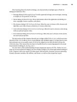
Now, let’s take a look at another figure and see if you can determine the switch and router
configurations without looking at the answer—no cheating! Figure 2.25 shows a router con-
nected to a 2960 switch with two VLANs. One host in each VLAN is assigned an IP address.
What are your router and switch configurations based on these IP addresses?
85711.book Page 119 Thursday, September 27, 2007 10:35 AM
120
Chapter 2
Configure, verify, and troubleshoot a switch with VLANs
FIGURE 2.25 Inter-VLAN example 3
Since the hosts don’t list a subnet mask, you have to look for the number of hosts used in
each VLAN to figure out the block size. VLAN 1 has 85 hosts and VLAN 2 has 115 hosts.
Each of these will fit in a block size of 128, which is a /25 mask, or 255.255.255.128.
You should know by now that the subnets are 0 and 128; the 0 subnet (VLAN 1) has a host
range of 1–126, and the 128 subnet (VLAN 2) has a range of 129–254. You can almost be fooled
since HostA has an IP address of 126, which makes it almost seem that HostA and B are in the
same subnet. But they’re not, and you’re way too smart by now to be fooled by this one!
Here is the switch configuration:
2960#config t
2960(config)#int f0/1
2960(config-if)#switchport mode trunk
2960(config-if)#int f0/2
2960(config-if)#switchport access vlan 1
2960(config-if)#int f0/3
2960(config-if)#switchport access vlan 2
Here is the router configuration:
ISR#config t
ISR(config)#int f0/0
ISR(config-if)#no ip address
ISR(config-if)#no shutdown
VLAN 1
85 Hosts
HostA
F0/1
172.16.10.129
F0/2
F0/3
172.16.10.126
VLAN 2
115 Hosts
HostB
85711.book Page 120 Thursday, September 27, 2007 10:35 AM
2.12 Configure, verify, and troubleshoot interVLAN routing
121
ISR(config-if)#int f0/0.1
ISR(config-subif)#encapsulation dot1q 1
ISR(config-subif)#ip address 172.16.10.1 255.255.255.128
ISR(config-subif)#int f0/0.2
ISR(config-subif)#encapsulation dot1q 2
ISR(config-subif)#ip address 172.16.10.254 255.255.255.128
I used the first address in the host range for VLAN 1 and the last address in the range for
VLAN 2, but any address in the range would work. You just have to configure the host’s
default gateway to whatever you make the router’s address.
Now, before we go on to the next example, I need to make sure that you know how to set
the IP address on the switch. Since VLAN 1 is typically the administrative VLAN, we’ll use an
IP address from that pool of addresses. Here’s how to set the IP address of the switch (I’m not
nagging, but you really should already know this!):
2960#config t
2960(config)#int vlan 1
2960(config-if)#ip address 172.16.10.2 255.255.255.128
2960(config-if)#no shutdown
Yes, you have to do a no shutdown on the VLAN interface.
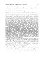
One more example, and then we’ll move on to VTP—another important subject that you
definitely don’t want to miss! In Figure 2.26 there are two VLANs. By looking at the router
configuration, what’s the IP address, mask, and default gateway of HostA? Use the last IP
address in the range for HostA’s address:
If you really look carefully at the router configuration (the hostname in this figure is just
Router), there is a simple and quick answer. Both subnets are using a /28, or 255.255.255.240
mask, which is a block size of 16. The router’s address for VLAN 1 is in subnet 128. The next
subnet is 144, so the broadcast address of VLAN 1 is 143 and the valid host range is 129–142.
So, the host address would be this:
IP Address: 192.168.10.142
Mask: 255.255.255.240
Default Gateway: 192.168.10.129
Exam Objectives
Remember that hosts in a VLAN can only communicate with hosts in the same VLAN. If
you have multiple VLANs and need inter-VLAN communication, you must configure a router
or buy a more expensive layer 3 switch to provide the routing on the backplane of the switch.
Remember how to create a Cisco “router on a stick” to provide inter-VLAN communication.
You can use a Cisco FastEthernet of Gigabit Ethernet interface to provide inter-VLAN routing.
The switch port connected to the router must be a trunk port, then you must create virtual inter-
faces (subinterfaces) on the router port for each VLAN connecting. The hosts in each VLAN will
use this subinterface address as their default gateway address.
85711.book Page 121 Thursday, September 27, 2007 10:35 AM
122
Chapter 2
Configure, verify, and troubleshoot a switch with VLANs
FIGURE 2.26 Inter-VLAN example 4
Remember how to create a subinterface on a router port. By creating a subinterface on a
router, you can use one router port to allow inter-VLAN communication. You must create a
subinterface for each VLAN. Here is an example on how to create a subinterface on a router
port for VLAN 2:
Router#config t
Rotuer(config)#int f0/0.1
Router(config-subif)#encapsulation dot1Q 2
Remember how to configure a trunk port on a 2960 switch. The 2960 switch only runs the
802.1q trunking method, so the command to trunk a port is simple:
Switch(config-if)#switchport mode trunk
VLAN 1
HostA
F0/1
192.168.10.17
VLAN 2
F0/2
F0/3
HostB
Router#config t
Router(config)#int f0/0
Router(config-if)#no ip address
Router(config-if)#no shutdown
Router(config-if)#int f0/0.1
Router(config-subif)# encapsulation dot1q 1
Router(config-subif)# ip address 192.168.10.129 255.255.255.240
Router(config-subif)# int f0/0.2
Router(config-subif)# encapsulation dot1q 2
Router(config-subif)# ip address 192.168.10.46 255.255.255.240
85711.book Page 122 Thursday, September 27, 2007 10:35 AM
2.13 Configure, verify, and troubleshoot VTP
123
2.13 Configure, verify, and
troubleshoot VTP
All Cisco switches are configured to be VTP servers by default. To configure VTP, first you
have to configure the domain name you want to use. And of course, once you configure the
VTP information on a switch, you need to verify it.
When you create the VTP domain, you have a bunch of options, including setting the
domain name, password, operating mode, and pruning capabilities of the switch. Use the vtp
global configuration mode command to set all this information. In the following example, I’ll
set the S1 switch to vtp server, the VTP domain to Lammle, and the VTP password to todd:
S1#config t
S1#(config)#vtp mode server
Device mode already VTP SERVER.
S1(config)#vtp domain Lammle
Changing VTP domain name from null to Lammle
S1(config)#vtp password todd
Setting device VLAN database password to todd
S1(config)#do show vtp password
VTP Password: todd
S1(config)#do show vtp status
VTP Version : 2
Configuration Revision : 0
Maximum VLANs supported locally : 255
Number of existing VLANs : 8
VTP Operating Mode : Server
VTP Domain Name : Lammle
VTP Pruning Mode : Disabled
VTP V2 Mode : Disabled
VTP Traps Generation : Disabled
MD5 digest : 0x15 0x54 0x88 0xF2 0x50 0xD9 0x03 0x07
Configuration last modified by 192.168.24.6 at 3-14-93 15:47:32
Local updater ID is 192.168.24.6 on interface Vl1 (lowest numbered VLAN
interface found)
Please make sure that you remember that all switches are set to VTP server mode by default,
and if you want to change any VLAN information on a switch, you absolutely must be in VTP
server mode. After you configure the VTP information, you can verify it with the show vtp
command as shown in the preceding output. The preceding switch output shows the VTP
domain, the VTP password, and the switch’s mode.
85711.book Page 123 Thursday, September 27, 2007 10:35 AM
124
Chapter 2
Configure, verify, and troubleshoot a switch with VLANs
Before we move onward to configuring the Core and the S2 switch with VTP information,
take a minute to reflect on the fact that the show vtp status output shows that the maximum
number of VLANs supported locally is only 255. Since you can create more than 1,000 VLANs
on a switch, this seems like it would definitely be a problem if you have more then 255 switches
and you’re using VTP. And, well, yes, it is problem—if you are trying to configure the 256th
VLAN on a switch, you’ll get a nice little error message stating that there are not enough hard-
ware resources available, and then it will shut down the VLAN and the 256th VLAN will show
up in suspended state in the output of the show vlan command. Not so good!
Let’s go to the Core and S2 switches and set them into the Lammle VTP domain. It is very
important to remember that the VTP domain name is case sensitive! VTP is not forgiving—one
teeny small mistake and it just won’t work.
Core#config t
Core(config)#vtp mode client
Setting device to VTP CLIENT mode.
Core(config)#vtp domain Lammle
Changing VTP domain name from null to Lammle
Core(config)#vtp password todd
Setting device VLAN database password to todd
Core(config)#do show vtp status
VTP Version : 2
Configuration Revision : 0
Maximum VLANs supported locally : 1005
Number of existing VLANs : 5
VTP Operating Mode : Server
VTP Domain Name : Lammle
VTP Pruning Mode : Disabled
VTP V2 Mode : Disabled
VTP Traps Generation : Disabled
MD5 digest : 0x2A 0x6B 0x22 0x17 0x04 0x4F 0xB8 0xC2
Configuration last modified by 192.168.10.19 at 3-1-93 03:13:16
Local updater ID is 192.168.24.7 on interface Vl1 (first interface found)
S2#config t
S2(config)#vtp mode client
Setting device to VTP CLIENT mode.
S2(config)#vtp domain Lammle
Changing VTP domain name from null to Lammle
S2(config)#vtp password todd
Setting device VLAN database password to todd
S2(config)#do show vtp status
VTP Version : 2
Configuration Revision : 0
85711.book Page 124 Thursday, September 27, 2007 10:35 AM
2.13 Configure, verify, and troubleshoot VTP
125
Maximum VLANs supported locally : 1005
Number of existing VLANs : 5
VTP Operating Mode : Client
VTP Domain Name : Lammle
VTP Pruning Mode : Disabled
VTP V2 Mode : Disabled
VTP Traps Generation : Disabled
MD5 digest : 0x02 0x11 0x18 0x4B 0x36 0xC5 0xF4 0x1F
Configuration last modified by 0.0.0.0 at 0-0-00 00:00:00
Nice—now that all our switches are set to the same VTP domain and password, the VLANs
I created earlier on the S1 switch should be advertised to the Core and S2 VTP client switches.
Let’s take a look using the show vlan brief command on the Core and S2 switch:
Core#sh vlan brief
VLAN Name Status Ports
1 default active Fa0/1,Fa0/2,Fa0/3,Fa0/4
Fa0/9,Fa0/10,Fa0/11,Fa0/12
Fa0/13,Fa0/14,Fa0/15,
Fa0/16,Fa0/17, Fa0/18, Fa0/19,
Fa0/20,Fa0/21, Fa0/22, Fa0/23,
Fa0/24, Gi0/1, Gi0/2
2 Sales active
3 Marketing active
4 Accounting active
[output cut]
S2#sh vlan bri
VLAN Name Status Ports
1 default active Fa0/3, Fa0/4, Fa0/5, Fa0/6
Fa0/7, Fa0/8, Gi0/1
2 Sales active
3 Marketing active
4 Accounting active
[output cut]
The VLAN database that I created on the S1 (2960) switch earlier in this chapter was
uploaded to the Core and S2 switch via VTP advertisements. VTP is a great way to keep VLAN
naming consistent across the switched network. We can now assign VLANs to the ports on the
Core and S1 switches, and they’ll communicate with the hosts in the same VLANs on the S1
switch across the trunked ports between switches.
85711.book Page 125 Thursday, September 27, 2007 10:35 AM
126
Chapter 2
Configure, verify, and troubleshoot a switch with VLANs
It’s imperative that you can assign a VTP domain name, set the switch to VTP
server mode, and create a VLAN!
Troubleshooting VTP
You connect your switches with crossover cables, the lights go green on both ends, and you’re
up and running! Yeah—in a perfect world, right? Don’t you wish it was that easy? Well, actu-
ally, it pretty much is—without VLANs, of course. But if you’re using VLANs—and you def-
initely should be—then you need to use VTP if you have multiple VLANs configured in your
switched network.
But here there be monsters: If VTP is not configured correctly, it (surprise!) will not work,
so you absolutely must be capable of troubleshooting VTP. Let’s take a look at a couple of
configurations and solve the problems. Study the output from the two following switches:
SwitchA#sh vtp status
VTP Version : 2
Configuration Revision : 0
Maximum VLANs supported locally : 64
Number of existing VLANs : 7
VTP Operating Mode : Server
VTP Domain Name : RouterSim
VTP Pruning Mode : Disabled
VTP V2 Mode : Disabled
VTP Traps Generation : Disabled
SwitchB#sh vtp status
VTP Version : 2
Configuration Revision : 1
Maximum VLANs supported locally : 64
Number of existing VLANs : 7
VTP Operating Mode : Server
VTP Domain Name : GlobalNet
VTP Pruning Mode : Disabled
VTP V2 Mode : Disabled
VTP Traps Generation : Disabled
So, what’s happening with these two switches? Why won’t they share VLAN information?
At first glance, it seems that both servers are in VTP server mode, but that’s not the problem.
Servers in VTP server mode will share VLAN information using VTP. The problem is that
they’re in two different VTP domains. SwitchA is in VTP domain RouterSim and SwitchB
85711.book Page 126 Thursday, September 27, 2007 10:35 AM
2.13 Configure, verify, and troubleshoot VTP
127
is in VTP domain GlobalNet. They will never share VTP information because the VTP domain
names are configured differently.
Now that you know how to look for common VTP domain configuration errors in your
switches, let’s take a look at another switch configuration:
SwitchC#sh vtp status
VTP Version : 2
Configuration Revision : 1
Maximum VLANs supported locally : 64
Number of existing VLANs : 7
VTP Operating Mode : Client
VTP Domain Name : Todd
VTP Pruning Mode : Disabled
VTP V2 Mode : Disabled
VTP Traps Generation : Disabled
There you are just trying to create a new VLAN on SwitchC, and what do you get for your trou-
ble? A loathsome error! Why can’t you create a VLAN on SwitchC? Well, the VTP domain name
isn’t the important thing in this example. What is critical here is the VTP mode. The VTP mode is
client, and a VTP client cannot create, delete, add, or change VLANs, remember? VTP clients only
keep the VTP database in RAM, and that’s not saved to NVRAM. So, in order to create a VLAN
on this switch, you’ve got to make the switch a VTP server first.
Here’s what will happen when you have the preceding VTP configuration:
SwitchC(config)#vlan 50
VTP VLAN configuration not allowed when device is in CLIENT mode.
So, to fix this problem, here’s what you need to do:
SwitchC(config)#vtp mode server
Setting device to VTP SERVER mode
SwitchC(config)#vlan 50
SwitchC(config-vlan)#
Wait, we’re not done. Now take a look at the output from these two switches and determine
why SwitchB is not receiving VLAN information from SwitchA:
SwitchA#sh vtp status
VTP Version : 2
Configuration Revision : 4
Maximum VLANs supported locally : 64
Number of existing VLANs : 7
VTP Operating Mode : Server
VTP Domain Name : GlobalNet
85711.book Page 127 Thursday, September 27, 2007 10:35 AM
128
Chapter 2
Configure, verify, and troubleshoot a switch with VLANs
VTP Pruning Mode : Disabled
VTP V2 Mode : Disabled
VTP Traps Generation : Disabled
SwitchB#sh vtp status
VTP Version : 2
Configuration Revision : 14
Maximum VLANs supported locally : 64
Number of existing VLANs : 7
VTP Operating Mode : Server
VTP Domain Name : GlobalNet
VTP Pruning Mode : Disabled
VTP V2 Mode : Disabled
VTP Traps Generation : Disabled
You may be tempted to say it’s because they’re both VTP servers, but that is not the prob-
lem. All your switches can be servers and they can still share VLAN information. As a matter
of fact, Cisco actually suggests that all switches stay VTP servers and that you just make sure
the switch you want to advertise VTP VLAN information has the highest revision number. If
all switches are VTP servers, then all of the switches will save the VLAN database. But SwitchB
isn’t receiving VLAN information from SwitchA because SwitchB has a higher revision num-
ber than SwitchA. It’s very important that you can recognize this problem.
There are a couple ways to go about resolving this issue. The first thing you could do is to
change the VTP domain name on SwitchB to another name, then set it back to GlobalNet,
which will reset the revision number to zero (0) on SwitchB. The second approach would be
to create or delete VLANs on SwitchA until the revision number passes the revision number
on SwitchB. I didn’t say the second way was better; I just said it’s another way to fix it!
Exam Objectives
Understand the purpose and configuration of VTP. VTP provides propagation of the VLAN
database throughout your switched network. All switches must be in the same VTP domain.
Remember the command to verify VTP. Unfortunately, there are not a lot of ways to verify
your VTP configuration. The best way is by using the command show vtp status. This
shows you your domain name, password, and revision number.
2.14 Configure, verify, and troubleshoot
RSTP operation
Configuring RSTP actually is as easy as configuring any of our other 802.1d extensions.
Considering how much better it is than 802.1d, you’d think the configuration would be
85711.book Page 128 Thursday, September 27, 2007 10:35 AM
2.14 Configure, verify, and troubleshoot RSTP operation
129
more complex, but we’re in luck—it’s not. So, let’s turn it on in the Core switch now and
see what happens:
Core#config t
Core(config)#spanning-tree mode ?
mst Multiple spanning tree mode
pvst Per-Vlan spanning tree mode
rapid-pvst Per-Vlan rapid spanning tree mode
Core(config)#spanning-tree mode rapid-pvst
Core(config)#
1d02h: %LINEPROTO-5-UPDOWN: Line protocol on Interface Vlan1,
changed state to down
1d02h: %LINEPROTO-5-UPDOWN: Line protocol on Interface Vlan1,
changed state to up
Sweet! The Core switch is now running the 802.1w STP. Let’s verify that:
Core(config)#do show spanning-tree
VLAN0001
Spanning tree enabled protocol rstp
Root ID Priority 32769
Address 000d.29bd.4b80
This bridge is the root
Hello Time 2 sec Max Age 20 sec Forward Delay 15 sec
Bridge ID Priority 32769 (priority 32768 sys-id-ext 1)
Address 000d.29bd.4b80
Hello Time 2 sec Max Age 20 sec Forward Delay 15 sec
Aging Time 300
Interface Role Sts Cost Prio.Nbr Type
Fa0/5 Desg FWD 19 128.5 P2p Peer(STP)
Fa0/6 Desg FWD 19 128.6 P2p Peer(STP)
Fa0/7 Desg FWD 19 128.7 P2p Peer(STP)
Fa0/8 Desg FWD 19 128.8 P2p Peer(STP)
Interesting . . . it looks like nothing really happened. I can see on my two other switches that
all ports have converged. Once everything was up, everything looked the same. 802.1d and
802.1w seem to be cohabiting with no problem.
But, if we were to look under the hood more closely, we’d see that the 802.1w switch has
changed from 802.1w BPDUs to 802.1d BPDUs on the ports connecting to the other switches
running 802.1d (which is all of them).
85711.book Page 129 Thursday, September 27, 2007 10:35 AM
130
Chapter 2
Configure, verify, and troubleshoot a switch with VLANs
The S1 and S2 switches believe that the Core switch is actually running 802.1d because the
Core reverted to 802.1d BPDUs just for them. And even though the S1 and S2 switches receive
the 802.1w BPDUs, they don’t understand them, so they simply drop them. However, the
Core does receive the 802.1d BPDUs and accepts them from the S1 and S2 switches, now
knowing which ports to run 802.1d on. In other words, turning 802.1w on for just one switch
didn’t really help our network at all!
One small annoying issue is that once the Core switch knows to send 802.1d BPDUs out
the ports connected to S1 and S2, it won’t change this automatically if the S1 and S2 switches
were later configured with 802.1w—we’d still need to reboot the Core switch to stop the
802.1d BPDUs.
Exam Objectives
Remember how to enable RSVP. To enable RSVP, use the following command:
Router(config)#spanning-tree mode rapid-pvst
Remember to reboot the switch when changing to RSVP. If you have a switch in your net-
work that is not running 802.1w, then you need to reboot your switches when enabling RSTP
to stop the 802.1d BPDU’s from being sent out the switch port.
2.15 Interpret the output of various
show and debug commands to verify
the operational status of a Cisco
switched network
For information on this objective, please review objective 2.6.
2.16 Implement basic switch security
(including: port security, trunk access,
management vlan other than vlan1, etc.)
So, just how do you stop someone from simply plugging a host into one of your switch ports—
or worse, adding a hub, switch, or access point into the Ethernet jack in their office? By
85711.book Page 130 Thursday, September 27, 2007 10:35 AM
131
default, MAC addresses will just dynamically appear in your MAC forward/filter database.
You can stop them in their tracks by using port security. Here are your options:
Switch#config t
Switch(config)#int f0/1
Switch(config-if)#switchport port-security ?
aging Port-security aging commands
mac-address Secure mac address
maximum Max secure addresses
violation Security violation mode
<cr>
You can see clearly in the preceding output that the switchport port-security
command can be used with four options. Personally, I like the port-security command
because it allows me to easily control users on my network. You can use the switchport
port-security mac-address mac-address command to assign individual MAC
addresses to each switch port, but if you choose to go there, you’d better have a lot of
time on your hands!
If you want to set up a switch port to allow only one host per port, and to shut down the
port if this rule is violated, use the following commands:
Switch#config t
Switch(config)#int f0/1
Switch(config-if)#switchport port-security maximum 1
Switch(config-if)#switchport port-security violation shutdown
These commands are probably the most popular because they prevent users from connect-
ing to a switch or access point that’s in their office. The maximum setting of 1 means that only
one MAC address can be used on that port; if the user tries to add another host on that seg-
ment, the switch port will shut down. If that happens, you’d have to manually go into the
switch and enable the port with a no shutdown command.
Probably one of my favorite commands is the sticky command. Not only does it perform a
cool function; it’s got a cool name! You can find this command under the mac-address command:
Switch(config-if)#switchport port-security mac-address sticky
Switch(config-if)#switchport port-security maximum 2
Switch(config-if)#switchport port-security violation shutdown
Basically, what this does is provide static MAC address security without having to type in
everyone’s MAC address on the network. As I said—cool!
In the preceding example, the first two MAC addresses into the port “stick” as static
addresses and will stay that way for however long you set the aging command for. Why did
I set it to 2? Well, I needed one for the PC/data and one for telephony/phone.
2.16 Implement basic switch security
85711.book Page 131 Thursday, September 27, 2007 10:35 AM
132
Chapter 2
Configure, verify, and troubleshoot a switch with VLANs
Configuring Trunk Ports
The 2960 switch only runs the IEEE 802.1Q encapsulation method. To configure trunking on
a Fast Ethernet port, use the interface command trunk [parameter]. It’s a tad different on
the 3560 switch, and I’ll show you that in the next section.
The following switch output shows the trunk configuration on interface fa0/8 as set to
trunk on:
S1#config t
S1(config)#int fa0/8
S1(config-if)#switchport mode trunk
The following list describes the different options available when configuring a switch interface:
switchport mode access I discussed this in the previous section, but this puts the inter-
face (access port) into permanent nontrunking mode and negotiates to convert the link into a
nontrunk link. The interface becomes a nontrunk interface regardless of whether the neigh-
boring interface is a trunk interface. The port would be a dedicated layer 2 port.
switchport mode dynamic auto This mode makes the interface able to convert the link
to a trunk link. The interface becomes a trunk interface if the neighboring interface is set to
trunk or desirable mode. This is now the default switchport mode for all Ethernet interfaces
on all new Cisco switches.
switchport mode dynamic desirable This one makes the interface actively attempt to
convert the link to a trunk link. The interface becomes a trunk interface if the neighboring
interface is set to trunk, desirable, or auto mode. I used to see this mode as the default on some
older switches, but not any longer. The default is dynamic auto now.
switchport mode trunk Puts the interface into permanent trunking mode and negotiates
to convert the neighboring link into a trunk link. The interface becomes a trunk interface even
if the neighboring interface isn’t a trunk interface.
switchport nonegotiate Prevents the interface from generating DTP frames. You can
use this command only when the interface switchport mode is access or trunk. You must man-
ually configure the neighboring interface as a trunk interface to establish a trunk link.
Dynamic Trunking Protocol (DTP) is used for negotiating trunking on a link
between two devices, as well as negotiating the encapsulation type of either
802.1Q or ISL. I use the nonegotiate command when I want dedicated trunk
ports no questions asked.
To disable trunking on an interface, use the switchport mode access command, which
sets the port back to a dedicated layer 2 switch port.
85711.book Page 132 Thursday, September 27, 2007 10:35 AM
133
Trunking with the Cisco Catalyst 3560 Switch
Okay, let’s take a look at one more switch—the Cisco Catalyst 3560. The configuration is
pretty much the same as it is for a 2960, with the exception that the 3560 can provide layer 3
services and the 2960 can’t. Plus, the 3560 can run both the ISL and the IEEE 802.1Q trunking
encapsulation methods—the 2960 can only run 802.1Q. With all this in mind, let’s take a
quick look at the VLAN encapsulation difference regarding the 3560 switch.
The 3560 has the encapsulation command, which the 2960 switch doesn’t:
Core(config-if)#switchport trunk encapsulation ?
dot1q Interface uses only 802.1q trunking encapsulation
when trunking
isl Interface uses only ISL trunking encapsulation
when trunking
negotiate Device will negotiate trunking encapsulation with peer on
interface
Core(config-if)#switchport trunk encapsulation dot1q
Core(config-if)#switchport mode trunk
As you can see, we’ve got the option to add either the IEEE 802.1Q (dot1q) encapsulation
or the ISL encapsulation to the 3560 switch. After you set the encapsulation, you still have to
set the interface mode to trunk. Honestly, it’s pretty rare that you’d continue to use the ISL
encapsulation method. Cisco is moving away from ISL—its new routers don’t even support it.
Defining the Allowed VLANs on a Trunk
As I’ve mentioned, trunk ports send and receive information from all VLANs by default, and
if a frame is untagged, it’s sent to the management VLAN. This applies to the extended range
VLANs as well.
But we can remove VLANs from the allowed list to prevent traffic from certain VLANs
from traversing a trunked link. Here’s how you’d do that:
S1#config t
S1(config)#int f0/1
S1(config-if)#switchport trunk allowed vlan ?
WORD VLAN IDs of the allowed VLANs when this port is in
trunking mode
add add VLANs to the current list
all all VLANs
except all VLANs except the following
none no VLANs
remove remove VLANs from the current list
S1(config-if)#switchport trunk allowed vlan remove ?
WORD VLAN IDs of disallowed VLANS when this port is in trunking mode
S1(config-if)#switchport trunk allowed vlan remove 4
16 Implement basic switch security
85711.book Page 133 Thursday, September 27, 2007 10:35 AM
134
Chapter 2
Configure, verify, and troubleshoot a switch with VLANs
The preceding command stopped the trunk link configured on S1 port f0/1, causing it to
drop all traffic sent and received for VLAN 4. You can try to remove VLAN 1 on a trunk link,
but it will still send and receive management like CDP, PAgP, LACP, DTP, and VTP, so what’s
the point?
To remove a range of VLANs, just use a hyphen:
S1(config-if)#switchport trunk allowed vlan remove 4-8
If by chance someone has removed some VLANs from a trunk link and you want to set the
trunk back to default, just use this command:
S1(config-if)#switchport trunk allowed vlan all
Or this command to accomplish the same thing:
S1(config-if)#no switchport trunk allowed vlan
Next, I want to show you how to configure pruning for VLANs before we start routing
between VLANs.
Changing or Modifying the Trunk Native VLAN
You really don’t want to change the trunk port native VLAN from VLAN 1, but you can, and
some people do it for security reasons. To change the native VLAN, use the following command:
S1#config t
S1(config)#int f0/1
S1(config-if)#switchport trunk ?
allowed Set allowed VLAN characteristics when interface is
in trunking mode
native Set trunking native characteristics when interface
is in trunking mode
pruning Set pruning VLAN characteristics when interface is
in trunking mode
S1(config-if)#switchport trunk native ?
vlan Set native VLAN when interface is in trunking mode
S1(config-if)#switchport trunk native vlan ?
<1-4094> VLAN ID of the native VLAN when this port is in
trunking mode
S1(config-if)#switchport trunk native vlan 40
S1(config-if)#^Z
So we’ve changed our native VLAN on our trunk link to 40, and by using the show
running-config command, I can see the configuration under the trunk link:
!
interface FastEthernet0/1
85711.book Page 134 Thursday, September 27, 2007 10:35 AM
135
switchport trunk native vlan 40
switchport trunk allowed vlan 1-3,9-4094
switchport trunk pruning vlan 3,4
!
Hold on there, partner! You didn’t think it would be this easy and would just start working,
did you? Sure you didn’t. Here’s the rub: If all switches don’t have the same native VLAN con-
figured on the trunk links, then we’ll start to receive this error:
19:23:29: %CDP-4-NATIVE_VLAN_MISMATCH: Native VLAN mismatch
discovered on FastEthernet0/1 (40), with Core FastEthernet0/7 (1).
19:24:29: %CDP-4-NATIVE_VLAN_MISMATCH: Native VLAN mismatch
discovered on FastEthernet0/1 (40), with Core FastEthernet0/7 (1).
Actually, this is a good, noncryptic error, so either we go to the other end of our trunk
link(s) and change the native VLAN or we set the native VLAN back to the default. Here’s
how we’d do that:
S1(config-if)#no switchport trunk native vlan
Now our trunk link is using the default VLAN 1 as the native VLAN. Just remember that
all switches must use the same native VLAN or you’ll have some serious problems. Now,
let’s mix it up by connecting a router into our switched network and configuring inter-
VLAN communication.
Port Security
As I said earlier in the chapter, it’s usually not a good thing to have your switches available for
anyone to just plug into and play around with. I mean, you demand wireless security, so why
wouldn’t you want switch security just as much?
The answer is, you do, and by using port security, you can limit the number of MAC
addresses that can be assigned dynamically to a port, set a static MAC address, and—here’s
my favorite part—set penalties for users who abuse your policy. Personally, I like to have the
port shut down when the security policy is violated and then make the abusers bring me a
memo from their boss explaining to me why they violated the security policy before I’ll enable
their port again. That usually really helps them remember to behave!
A secured switch port can associate anywhere from 1 to 8,192 MAC addresses, but the
’50 series can support only 192, which seems like enough to me. You can choose to allow the
switch to learn these values dynamically, or you can set a static address for each port using
the switchport port-security mac-address mac-address command.
So, let’s set port security on our S1 switch now. Ports fa0/3 and fa0/4 have only one device con-
nected in our lab. By using port security, we can know for certain that no other device can connect
once our host in port fa0/2 and the phone in fa0/3 are connected. Here’s how we’ll do that:
S1#config t
Enter configuration commands, one per line. End with CNTL/Z.
16 Implement basic switch security
85711.book Page 135 Thursday, September 27, 2007 10:35 AM
136
Chapter 2
Configure, verify, and troubleshoot a switch with VLANs
S1(config)#int range fa0/3 - 4
S1(config-if-range)#switchport port-security maximum ?
<1-8192> Maximum addresses
S1(config-if-range)#switchport port-security maximum 1
S1(config-if-range)#switchport port-security mac-address sticky
S1(config-if-range)#switchport port-security violation ?
protect Security violation protect mode
restrict Security violation restrict mode
shutdown Security violation shutdown mode
S1(config-if-range)#switchport port-security violation shutdown
S1(config-if-range)#exit
The preceding command set port security on port fa0/3 and fa0/4 to allow a maximum
association of one MAC address, and only the first MAC address associated to the port will
be able to send frames through the switch. If a second device with a different MAC address
were to try and send a frame into the switch, the port would be shut down because of our
violation command. I use the sticky command because I am way too lazy to type in all the
MAC addresses of each device by hand!
There are two other modes you can use instead of just shutting down the port. The protect
mode means that another host can connect, but its frames will just be dropped. Restrict mode
is also pretty cool—it alerts you via SNMP that a violation has occurred on a port. You can
then call the abuser and tell them they’re so busted—you can see them, you know what they
did, and they’re in big-time trouble!
In our connection between switches we have redundant links, so it’s best to let STP run on
those links (for now). But on our R1 and R2 switches, we also have hosts connected to port
fa0/3 and fa0/4 (not the Core). So let’s turn STP off on those ports.
Exam Objectives
Remember how to set port security on a switch port. If you want to set up a switch port to
allow only one host per port, and to shut down the port if this rule is violated, use the follow-
ing commands:
Switch#config t
Switch(config)#int f0/1
Switch(config-if)#switchport port-security maximum 1
Switch(config-if)#switchport port-security violation shutdown
Remember how to configure a trunk port on a 2960 switch. The 2960 switch only runs the
802.1q trunking method, so the command to trunk a port is simple:
Switch(config-if)#switchport mode trunk
85711.book Page 136 Thursday, September 27, 2007 10:35 AM
Review Questions
137
Review Questions
1. You need to configure a Catalyst switch so that it can be managed remotely. Which of the
following would you use to accomplish this task?
A. Switch(configs)#int fa0/1
B. Switch(configs-if)#ip address 192.168.10.252 255.255.255.0
C. Switch(configs-if)#no shut
D. Switch(configs)#int vlan 1
E. Switch(configs-if)#ip address 192.168.10.252 255.255.255.0
F. Switch(configs-if)#ip default-gateway 192.168.10.254 255.255.255.0
G. Switch(configs)#ip default-gateway 192.168.10.254
H. Switch(configs)#int vlan 1
I. Switch(configs-if)#ip address 192.168.10.252 255.255.255.0
J. Switch(configs-if)#no shut
K. Switch(configs)#ip default-network 192.168.10.254
L. Switch(configs)#int vlan 1
M. Switch(configs-if)#ip address 192.168.10.252 255.255.255.0
N. Switch(configs-if)#no shut
2. What does a switch do when a frame is received on an interface and the destination hardware
address is unknown or not in the filter table?
A. Forwards the switch to the first available link
B. Drops the frame
C. Floods the network with the frame looking for the device
D. Sends back a message to the originating station asking for a name resolution
3. If a switch receives a frame and the source MAC address is not in the MAC address table but
the destination address is, what will the switch do with the frame?
A. Discard it and send an error message back to the originating host
B. Flood the network with the frame
C. Add the source address and port to the MAC address table and forward the frame out the
destination port
D. Add the destination to the MAC address table and then forward the frame
85711.book Page 137 Thursday, September 27, 2007 10:35 AM
138
Chapter 2
Configure, verify, and troubleshoot a switch with VLANs
4. You want to run the new 802.1w on your switches. Which of the following would enable
this protocol?
A. Switch(config)#spanning-tree mode rapid-pvst
B. Switch#spanning-tree mode rapid-pvst
C. Switch(config)#spanning-tree mode 802.1w
D. Switch#spanning-tree mode 802.1w
5. In which circumstance are multiple copies of the same unicast frame likely to be transmitted
in a switched LAN?
A. During high-traffic periods
B. After broken links are reestablished
C. When upper-layer protocols require high reliability
D. In an improperly implemented redundant topology
6. Which command was used to produce the following output:
Vlan Mac Address Type Ports
1 0005.dccb.d74b DYNAMIC Fa0/1
1 000a.f467.9e80 DYNAMIC Fa0/3
1 000a.f467.9e8b DYNAMIC Fa0/4
1 000a.f467.9e8c DYNAMIC Fa0/3
1 0010.7b7f.c2b0 DYNAMIC Fa0/3
1 0030.80dc.460b DYNAMIC Fa0/3
A. show vlan
B. show ip route
C. show mac address-table
D. D. show mac address-filter
7. If you want to disable STP on a port connected to a server, which command would you use?
A. disable spanning-tree
B. spanning-tree off
C. spanning-tree security
D. spanning-tree portfast
85711.book Page 138 Thursday, September 27, 2007 10:35 AM
Review Questions
139
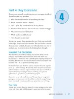
8. Refer to the graphic. Why does the switch have two MAC addresses assigned to the FastEth-
ernet 0/1 port in the switch address table?
A. Data from HostC and HostD have been received by the switch port FastEthernet 0/1.
B. Data from two of the devices connected to the switch have been forwarded out to HostD.
C. HostC and HostD had their NIC replaced.
D. HostC and HostD are on different VLANs.
9. Layer 2 switching provides which of the following? (Choose four.)
A. Hardware-based bridging (ASIC)
B. B. Wire speed
C. C. Low latency
D. D. Low cost
E. E. Routing
F. WAN services
85711.book Page 139 Thursday, September 27, 2007 10:35 AM
140
Chapter 2
Configure, verify, and troubleshoot a switch with VLANs
10. You type show mac address-table and receive the following output:
Switch#sh mac address-table
Vlan Mac Address Type Ports
1 0005.dccb.d74b DYNAMIC Fa0/1
1 000a.f467.9e80 DYNAMIC Fa0/3
1 000a.f467.9e8b DYNAMIC Fa0/4
1 000a.f467.9e8c DYNAMIC Fa0/3
1 0010.7b7f.c2b0 DYNAMIC Fa0/3
1 0030.80dc.460b DYNAMIC Fa0/3
Suppose that the above switch received a frame with the following MAC addresses:
Source MAC: 0005.dccb.d74b
Destination MAC: 000a.f467.9e8c
What will it do?
A. It will discard the frame.
B. It will forward the frame out port Fa0/3 only.
C. It will forward it out Fa0/1 only.
D. It will send it out all ports except Fa0/1.
85711.book Page 140 Thursday, September 27, 2007 10:35 AM
Answers to Review Questions
141
Answers to Review Questions
1. Answer:C. Explanation:To manage a switch remotely, you must set an IP address under the
management VLAN, which is, by default, interface vlan 1. Then, from global configura-
tion mode, you set the default gateway with the ip default-gateway command.
2. Answer:C. Explanation:Switches flood all frames that have an unknown destination address.
If a device answers the frame, the switch will update the MAC address table to reflect the loca-
tion of the device.
3. Answer:C. Explanation:Since the source MAC address is not in the MAC address table, the
switch will add the source address and the port it is connected to into the MAC address table
and then forward the frame to the outgoing port.
4. Answer:A. Explanation:802.1w is the also called Rapid Spanning-Tree Protocol. It is not
enabled by default on Cisco switches, but it is a better STP to run since it has all the fixes that
the Cisco extensions provide with 802.1d.
5. Answer:D. Explanation:If the Spanning-Tree Protocol is not running on your switches and you
connect them together with redundant links, you will have broadcast storms and multiple
frame copies
6. Answer:C. Explanation:The command show mac address-table will display the forward/
filter table, also called a CAM table on a switch.
7. Answer:D. Explanation:If you have a server or other devices connected into your switch that
you’re totally sure won’t create a switching loop if STP is disabled, you can use something
called portfast on these ports. Using it means that the port won’t spend the usual 50 seconds
to come up while STP is converging.
8. Answer:A. Explanation:A switch can have multiple MAC addresses associated with a port. In
the graphic, a hub is connected to port Fa0/1, which has two hosts connected.
9. Answer:A, B, C, D. Explanation:Switches, unlike bridges, are hardware based. Cisco says its
switches are wire speed and provide low latency, and I guess they are low cost compared to
their prices in the 1990s.
10. Answer:B. Explanation:Since the destination MAC address is in the MAC address table
(forward/filter table), it will send it out port Fa0/3 only.
85711.book Page 141 Thursday, September 27, 2007 10:35 AM
85711.book Page 142 Thursday, September 27, 2007 10:35 AM
Chapter
3
Implement an IP
addressing scheme
and IP Services to
meet network
requirements in a
medium-size
Enterprise branch
office network.
THE CISCO CCNA EXAM OBJECTIVES
COVERED IN THIS CHAPTER INCLUDE:
3.1 Describe the operation and benefits of using private
and public IP addressing
3.2 Explain the operation and benefits of using DHCP
and DNS
3.3 Configure, verify, and troubleshoot DHCP and DNS
operation on a router (including CLI/SDM)
3.4 Implement static and dynamic addressing services
for hosts in a LAN environment
3.5 Calculate and apply an addressing scheme, including
VLSM IP addressing design, to a network
3.6 Determine the appropriate classless addressing
scheme using VLSM and summarization to satisfy
addressing requirements in a LAN/WAN environment
85711.book Page 143 Thursday, September 27, 2007 10:35 AM