Practical Design Calculations for Groundwater and Soil Remediation - Chapter 7 potx
Bạn đang xem bản rút gọn của tài liệu. Xem và tải ngay bản đầy đủ của tài liệu tại đây (404.69 KB, 26 trang )
Kuo, Jeff "VOC-laden air treatment"
Practical Design Calculations for Groundwater and Soil Remedition
Boca Raton: CRC Press LLC,1999
©1999 CRC Press LLC
chapter seven
VOC-laden air treatment
Remediation of contaminated soil and groundwater often results in trans-
ferring organic contaminants into the air phase. Development and imple-
mentation of an air emission control strategy should be an integral part of
the overall remediation program. Air emission control may affect the cost-
effectiveness of a specific remedial alternative.
Common sources of VOC-laden off-gas from soil/groundwater remedi-
ation activities include soil vapor extraction, air sparging, air stripping,
solidification/stabilization, and bioremediation. This chapter illustrates the
design calculations for commonly used treatment technologies: activated
carbon adsorption, direct incineration, catalytic incineration, IC engines, and
biofiltration.
VII.1 Activated carbon adsorption
Process description
Activated carbon adsorption is one of the most commonly used air pollution
control processes for reducing VOC emission from soil/groundwater reme-
diation. The process is very effective in removing a wide range of VOCs.
The most common form of activated carbon for this type of application is
granular activated carbon (GAC).
Activated carbon has a fixed capacity or a limited number of active
adsorption sites. Once the adsorbing contaminants occupy most of the avail-
able sites, the adsorption efficiency will drop significantly. If the operation
is continued beyond this point, the breakthrough point will be reached and
the effluent concentration will increase sharply. Eventually, carbon would
be “saturated,” “exhausted,” or “spent” when all sites are occupied. The
spent carbon needs to be regenerated or disposed of.
Two pretreatment processes are often required to optimize the perfor-
mance of GAC systems. The first is cooling, and the other is dehumidifica-
©1999 CRC Press LLC
tion. Adsorption of VOCs is generally exothermic, which is favored by lower
temperatures. As a rule of thumb, the waste air stream needs to be cooled
down below 130°F. Water vapor will compete with VOCs in the waste air
stream for available adsorption sites. The relative humidity of the waste air
stream generally should be reduced to 50% or less.
GAC sizing criteria
Various GAC adsorber designs are commercially available. Two of the most
common ones are (1) canister systems with off-site regeneration and (2)
multiple-bed systems with on-site batch regeneration (while some of the
adsorbers are in adsorption cycle, the others are in regeneration cycle).
Sizing of the GAC systems depends primarily on the following parameters:
1. Volumetric flow rate of VOC-laden gas stream
2. Concentration or mass loading of VOCs
3. Adsorption capacity of GAC
4. Desired GAC regeneration frequency
The flow rate determines the size or cross-sectional area of the GAC bed,
the size of the fan and motor, and the duct diameter. The other three, mass
loading, GAC adsorption capacity, and regeneration frequency, determine
the amount of GAC required for a specific project. Design of vapor-phase
activated carbon systems is basically the same as that for liquid-phase acti-
vated carbon systems, as described in Section VI.2.
VII.1.1 Adsorption isotherm and adsorption capacity
The adsorption capacity of GAC depends on the type of GAC and the type
of VOC compounds and their concentration, temperature, and presence of
other species competing for adsorption. At a given temperature, a relation-
ship exists between the mass of the VOC adsorbed per unit mass GAC and
the concentration (or partial pressure) of VOC in the waste air stream. For
most of the VOCs, the adsorption isotherms can be fitted well by a power
curve, also known as the Freundlich isotherms (also see Eq. VI.2.2):
[Eq. VII.1.1]
where
q
= equilibrium adsorption capacity, lb VOC/lb GAC,
P
VOC
= partial
pressure of VOC in the waste air stream, psi, and
a, m
= empirical constants.
The empirical constants of the Freundlich Isotherms for selected VOCs
are listed in Table VII.1.A. It should be noted that the values of these empir-
ical constants are for a specific type of GAC only and should not be used
outside the specified range.
The actual adsorption capacity in the field applications should be lower
than the equilibrium adsorption capacity. Normally, design engineers take
qaP
VOC
m
= ()
©1999 CRC Press LLC
25 to 50% of the equilibrium value as the design adsorption capacity as a
factor of safety. Therefore,
[Eq. VII.1.2]
The maximum amount of contaminants that can be removed or held
(
M
removal
) by a given amount of GAC can be determined as
[Eq. VII.1.3]
where
M
GAC
is the mass,
V
GAC
is the volume, and
ρ
b
is the bulk density of
the GAC, respectively.
The following procedure can be used to determine the adsorption capac-
ity of a GAC adsorber:
Step 1: Determine the theoretical adsorption capacity by using Eq.
VII.1.1.
Step 2: Determine the actual adsorption capacity by using Eq. VII.1.2.
Step 3: Determine the amount of activated carbon in the adsorber.
Step 4: Determine the maximum amount of contaminants that can be
held by the adsorber using Eq. VII.1.3.
Information needed for this calculation
• Adsorption isotherm
• Contaminant concentration of the influent waste air stream,
P
VOC
Table VII.1.A
Empirical Constants for Selected
Adsorption Isotherms
Compounds
Adsorption
Temperature (°F)
am
Range of
P
VOC
(psi)
Benzene 77 0.597 0.176 0.0001–0.05
Toluene 77 0.551 0.110 0.0001–0.05
m
-Xylene 77 0.708 0.113 0.0001–0.001
77 0.527 0.0703 0.001–0.05
Phenol 104 0.855 0.153 0.0001–0.03
Chlorobenzene 77 1.05 0.188 0.0001–0.01
Cyclohexane 100 0.508 0.210 0.0001–0.05
Dichloroethane 77 0.976 0.281 0.0001–0.04
Trichloroethane 77 1.06 0.161 0.0001–0.04
Vinyl chloride 100 0.20 0.477 0.0001–0.05
Acrylonitrile 100 0.935 0.424 0.0001–0.05
Acetone 100 0.412 0.389 0.0001–0.05
From U.S. EPA, Control Technologies for Hazardous Air Pollutants,
EPA/625/6-91/014, U.S. EPA, Washington, DC, 1991.
actual theoretical
= ( %)( )50
MqM
qV
removal actual
GAC
actual
GAC
b
=
=
()( )
( )[( )( )]ρ
©1999 CRC Press LLC
• Volume of the GAC,
V
GAC
• Bulk density of the GAC,
ρ
b
Example VII.1.1 Determine the capacity of a GAC adsorber
The off-gas from a soil venting project is to be treated by GAC adsorbers.
The
m
-xylene concentration in the off-gas is 800 ppmV. The air flow rate out
of the extraction blower is 200 cfm, and the temperature of the air is ambient.
Two 1000-lb activated carbon adsorbers are proposed. Determine the maxi-
mum amount of
m
-xylene that can be held by each GAC adsorber before
regeneration. Use the isotherm data in Table VII.1.A.
Solution:
a. Convert the xylene concentration from ppmV to psi as
P
VOC
= 800 ppmV = 800
×
10
–6
atm = 8.0
×
10
–4
atm
= (8.0
×
10
–4
atm)(14.7 psi/atm) = 0.0118 psi
Obtain the empirical constants for the adsorption isotherm from Table
VII.1.A and then apply Eq. VII.1.1 to determine the equilibrium ad-
sorption capacity as
q
=
a
(
P
VOC
)
m
= (0.527)(0.0118)
0.0703
= 0.386 lb/lb
b. The actual adsorption capacity can be found by using Eq. VII.1.2 as
q
actual
= (50%)
q
theoretical
= (50%)(0.386) = 0.193 lb/lb
c. Amount of xylene that can be retained by an adsorber before the GAC
becomes exhausted = (amount of the GAC)(actual adsorption capac-
ity) = (1000 lbs/unit)(0.193 lb xylene/lb GAC) = 193 lb xylene/unit.
Discussion
1. The adsorption capacity of vapor-phase GAC is typically in the neigh-
borhood of 0.1 lb/lb (or 0.1 kg/kg), which is much higher than the
adsorption capacity of liquid-phase GAC, typically in the neighbor-
hood of 0.01 lb/lb.
2. Care should be taken to use matching units for
P
VOC
and
q
in the
isotherm equations.
3. The influent contaminant concentration in the air stream, not the
effluent concentration, should be used in the isotherm equations to
determine the adsorption capacity.
4. There are two sets of empirical constants for
m
-xylene; one should
always check the applicable range for the empirical constants.
©1999 CRC Press LLC
VII.1.2 Cross-sectional area and height of GAC adsorbers
To achieve efficient adsorption, the air flow rate through the activated carbon
should be kept as low as possible. The practical design air flow velocity is
often selected to be 60 ft/min or less, and 100 ft/min is considered as the
maximum value. This design parameter is often used to determine the
required cross-sectional area of the GAC adsorbers (
A
GAC
):
[Eq. VII.1.4]
where
Q
is the air flow velocity. The design height of the adsorber is normally
2 ft or greater to provide a sufficiently large adsorption zone.
Example VII.1.2 Required cross-sectional area of GAC adsorbers
Referring to the remediation project described in Example VII.1.1, the 1000-
lb GAC units are out of stock. To avoid delay of remediation, off-the-shelf
55-gal activated carbon units are proposed on an interim basis. The type of
carbon in the 55-gal units is the same as that in the 1000-lb units. The vendor
also provided the following information regarding the units:
Diameter of carbon packing bed in each 55-gal drum = 1.5 ft
Height of carbon packing bed in each 55-gal drum = 3 ft
Bulk density of the activated carbon = 28 lb/ft
3
Determine (a) the amount of activated carbon in each 55-gal unit, (b) the
amount of xylene that each unit can remove before being exhausted, and (c)
the minimum number of the 55-gal units needed.
Solution:
a. Volume of the activated carbon inside a 55-gal drum = (
π
r
2
)(
h
)
= (
π
)[(1.5/2)
2
](3) = 5.3 ft
3
Amount of the activated carbon inside a 55-gal drum = (
V
)(
ρ
b
)
= (5.3 ft
3
)(28 lb/ft
3
) = 148 lbs
b. Amount of xylene that can be retained by a drum before the GAC
becomes exhausted
= (amount of the GAC)(actual adsorption capacity)
= (148 lbs/drum)(0.193 lb xylene/lb GAC) = 28.6 lb xylene/drum
A
Q
Air FlowVelocity
GAC
=
©1999 CRC Press LLC
c. Assuming a design air flow velocity of 60 ft/min, the required cross-
sectional area for the GAC adsorption can be found by using Eq.
VII.1.4 as
If the adsorption system is tailor made, then a system with a cross-
sectional area of 3.33 ft
2
will do the job. However, the off-the-shelf 55-
gal drums are to be used, so we need to determine the number of
drums that will provide the required cross-sectional area.
Area of the activated carbon inside a 55-gal drum = (
π
r
2
) = (
π
)[(1.5/2)
2
]
= 1.77 ft
2
/drum.
Number of drums in-parallel to meet the required hydraulic loading
rate = (3.33 ft
2
) ÷ (1.77 ft
2
/drum) = 1.88 drums.
So, use two drums in parallel to provide the required cross-sectional
area. The total cross-sectional area of two drums is equal to 3.54 ft
2
(= 1.77
×
2).
Discussion
1. The bulk density of vapor-phase GAC is typically in the neighborhood
of 30 lb/ft
3
. The amount of activated carbon in a 55-gal drum is
approximately 150 pounds.
2. The minimum number of 55-gal drums for this project is two to meet
the air flow velocity requirement. The actual number of drums should
be more to meet the monitoring requirements or the desirable fre-
quency of change-out. If multiple GAC adsorbers are used, the ad-
sorbers are often arranged in series and/or in parallel. If two adsorb-
ers are arranged in series, the monitoring point can be located at the
effluent of the first adsorber. A high effluent concentration from the
first adsorber indicates that this adsorber is reaching its capacity. The
first adsorber is then taken off-line, and the second adsorber is shifted
to be the first adsorber. Consequently, the capacity of both adsorbers
can be fully utilized and the compliance requirements can also be met.
If there are two parallel streams of adsorbers, one stream can always
be taken off-line for regeneration or maintenance, and the continuous
operation of the system is secured.
VII.1.3 Contaminant removal rate by the activated carbon
adsorber
The removal rate by a GAC adsorber (
R
removal
) can be calculated by using the
following formula:
[Eq. VII.1.5]
A
Q
Air FlowVelocity
GAC
===
200
60
333.ft
2
RGGQ
removal
in out
=−()
©1999 CRC Press LLC
In practical applications, the effluent concentration (
G
out
) is kept below
the discharge limit, which is often very low. Therefore, for a factor of safety,
the term of
G
out
can be deleted from Eq. VII.1.5 in design. The mass removal
rate is then the same as the mass loading rate (
R
loading
):
[Eq. VII.1.6]
The mass loading rate is nothing but the multiplication product of the
air flow rate and the contaminant concentration. As mentioned earlier, the
contaminant concentration in the air is often expressed in ppmV or ppbV.
In the mass loading rate calculation, the concentration has to be converted
to mass concentration units as
[Eq. VII.1.7]
or
[Eq. VII.1.8]
where MW is the molecular weight of the compound.
Example VII.1.3 Determine the mass removal rate by the GAC
adsorbers
Referring to the remediation project described in Example VII.1.2, the dis-
charge limit for xylene is 100 ppbV. Determine the mass removal rate by the
two 55-gal GAC units.
Solution:
a. Use Eq. VII.1.8 to convert the ppmV concentration to lb/ft
3
. Molecular
weight of xylene (C
6
H
4
(CH
3
)
2
) = 12
×
8 + 1
×
10 = 106.
RR GQ
removal loading
in
~()=
1ppmV
MW
22.4
[mg/m ] at 0 C
MW
24.05
[mg/m ] at 20 C
MW
24.5
[mg/m ] at 25 C
3
3
3
=°
=°
=°
1ppmV
MW
359
10 [lb/ft ] at 32 C
MW
385
10 [lb/ft ] at 68 C
MW
392
10 [lb/ft ] at77 C
-6 3
-6 3
-6 3
=× °
=× °
=× °
©1999 CRC Press LLC
800 ppmV = (800)(0.27
×
10
–6
) = 2.16
×
10
–4
lb/ft
3
.
b. Use Eq. VII.1.6 to determine the mass removal rate:
R
removal
~ (
G
in
)
Q
=
(2.16
×
10
–4
lb/ft
3
)(200 ft
3
/min) = 0.65 lb/min = 93 lb/d
VII.1.4 Change-out (or regeneration) frequency
Once the activated carbon reaches its capacity, it should be regenerated or
disposed of. The time interval between two regenerations or the expected
service life of a fresh batch of activated carbon can be found by dividing the
capacity of activated carbon with the contaminant removal rate (
R
removal
) as
[Eq. VII.1.9]
Example VII.1.4 Determine the change-out (or regeneration)
frequency of the GAC adsorbers
Referring to the remediation project described in Example VII.1.3, the dis-
charge limit for xylene is 100 ppbV. Determine the service life of the two 55-
gal GAC units.
Solution:
As shown in Example VII.1.2, the amount of xylene that each drum can
retain before being exhausted is 28.6 lbs. Use Eq. VII.1.9 to determine the
service life of two drums:
Discussion
1. Although two drums in parallel can provide a sufficient cross-section-
al area for adequate air flow velocity, the relatively high contaminant
concentration makes the service life of the two 55-gal drums unac-
ceptably short.
2. A 55-gal activated carbon drum normally costs several hundred dol-
lars. In this example, two drums last less than 90 minutes. The labor
and disposal costs should also be added, and it makes this option
prohibitive. A GAC system with on-site regeneration or other treat-
ment alternatives should be considered.
1
106
392
10 0 27 10 77
663
ppmV lb ft at F=×=× °
−−
./
T
M
R
removal
removal
=
T
M
R
removal
removal
== =<
(2)(28.6 lb)
0.65 lb/min
88 min 1.5 hrs
©1999 CRC Press LLC
VII.1.5 Amount of carbon required (on-site regeneration)
If the concentration of the waste air stream is high, a GAC system with on-
site regeneration capability would become an attractive option. The amount
of GAC required for on-site regeneration depends on the mass loading, the
adsorption capacity of GAC, the adsorption time between two regenerations,
and the ratio between the number of GAC beds in regeneration cycle and
the number of GAC beds in adsorption cycle. It can be determined by using
the following formula:
[Eq. VII.1.10]
where
M
GAC
= total amount of GAC required,
T
ad
= adsorption time between
two regeneration (desorption),
N
ads
= number of GAC beds in adsorption
phase, and
N
des
= number of GAC beds in desorption (regeneration) phase.
Example VII.1.5 Determine the amount of GAC required for
on-site regeneration
Referring to the remediation project described in Example VII.1.3, an on-site
regeneration GAC is proposed to deal with the high contaminant loading. The
system consists of three adsorbers. Two of the three adsorbers are in adsorption
cycle and the other one is in regeneration cycle. The adsorption cycle time is
two hours. Determine the amount of GAC required for this system.
Solution:
The total amount of GAC required in all three adsorbers can be determined
by using Eq. VII.1.10 as
So, 202 pounds of GAC in each bed are required.
VII.2 Thermal oxidation
Thermal processes are commonly used to treat VOC-laden air. Thermal
oxidation, catalytic oxidation, and internal combustion (IC) engines are pop-
ular thermal processes. The key components of thermal treatment system
design are referred to as the “three T’s,” which are combustion temperature,
M
RT
q
N
N
GAC
removal ad des
ad
=+
1
M
RT
q
N
N
GAC
removal ad des
ad
=+
=+
=
1
(0.65 lb/min)(120 min)
(0.193 lb/lb)
1
1
2
606 lbs
©1999 CRC Press LLC
residence time (also called “retention time” or “dwell time”), and turbulence.
They basically determine a reactor’s size and its destruction efficiency. For
example, to achieve good thermal destruction, the VOC-laden gas should
be held in a thermal oxidizer for a sufficient residence time (normally 0.3 to
1.0 seconds) at a temperature at least 100°F above the autoignition temper-
atures of the compounds in the VOC-laden gas stream. In addition, sufficient
turbulence must be maintained in the oxidizer to assure good mixing and
complete combustion of the contaminants. Other important parameters to
be considered include influent concentration (heating value) and auxiliary
fuel and supplementary air requirements.
Discussions on the combustion basics for thermal oxidation will be pre-
sented here and they are applicable to other thermal processes with little
modification needed.
VII.2.1 Air flow rate vs. temperature
The volumetric air flow rate is commonly expressed in ft
3
/min, i.e., cubic
feet per minute (cfm). Since the volumetric flow rate of an air stream is a
function of temperature and the air stream undergoes zones of different
temperatures in a thermal process, the air flow rate is further shown as actual
cfm (acfm) or standard cfm (scfm). The unit of acfm refers to the volumetric
flow rate under the actual temperature, while scfm is the flow rate at stan-
dard conditions. The standard conditions are the basis for comparison.
Unfortunately, the definition of the standard conditions is not universal. For
U.S. EPA the standard conditions are at 77°F (25°C) and 1 atmospheric
pressure; however, it is 68°F (20°C) and 1 atm for the South Coast Air Quality
Management Districts in southern California. In addition, 60°F is also com-
monly used in the literature or in books as the temperature for the standard
conditions. One should follow the regulatory requirements and use the
appropriate reference temperature for a specific project. A standard temper-
ature of 77°F is used in this chapter, unless otherwise specified.
Conversions between acfm and scfm for a given air stream can be easily
made using the following formula which assumes that the ideal gas law is valid:
[Eq. VII.2.1]
where T is the actual temperature in °F and the addition of 460 is to convert
the temperature from °F to degree Rankine.
Example VII.2.1 Conversion between the actual and standard air
flow rates
A thermal oxidizer was used to treat the off-gas from a soil venting process.
To achieve the required removal efficiency the oxidizer was operated at
Q
Q
T
actual temperatureT inacfm@,
standard,inscfm
=
+
+
460
460 77
©1999 CRC Press LLC
1400°F. The flow rate at the exit of the oxidizer was 550 ft
3
/min. What would
be the exit flow rate expressed in scfm? The temperature of the effluent air
from the final discharge stack was 200°F. If the diameter of the final stack
was 4 in, determine the air flow velocity from the discharge stack.
Solution:
a. Use Eq. VII.2.1 to convert acfm to scfm as
So,
Q = 158.8 scfm.
b. Use Eq. VII.2.1 to determine the flow rate from the stack:
So, Q = 195.2 acfm @ 200°F.
The discharge velocity, v = Q/A = Q ÷ (πr
2
) = 195.2 ft
3
/min ÷ [π(2/12)
2
ft
2
] = 2240 ft/min.
Discussion. If the actual flow rate at one temperature is known, it can
be used to determine the flow rate at another temperature by using the
following formula:
[Eq. VII.2.2]
The stack flow rate in this example can be directly determined from the
exit flow rate from the oxidizer as
Thus, Q
actual
@ 200°F = 195.2 acfm.
VII.2.2 Heating values of an air stream
Organic compounds generally contain high heating values. These organic
compounds can also serve as energy sources for combustion. The higher the
organic concentration in a waste stream, the higher the heat content is and
Q
Q
T
Q
actual temperatureT inacfm@,
standard,inscfm standard,inscfm
=
+
+
=
+
+
=
460
460 77
460 1400
460 77
550
Q
Q
T
Q
actual temperatureT inacfm actual temperatureT inacfm@, @,
.
standard,inscfm
=
+
+
=
+
+
=
460
460 77
460 200
460 77 158 8
QT
QT
T
T
actual
actual
@
@
1
2
1
2
460
460
=
+
+
QT
QT
T
TQ
actual
actual actual
@
@@
1
2
1
2
460
460
550
200
460 1400
460 200
=
+
+
=
°
=
+
+F
©1999 CRC Press LLC
the lower the requirement for auxiliary fuel would be. If the heating value
of a compound is not available, the following Dulong’s formula can be used:
[Eq. VII.2.3]
where C, H, O, and S are the percentages by weight of these elements in the
compound. Eq. VII.2.3 can also be used to estimate the heating value of a
solid waste. The heating value of an air stream containing organics can be
determined by
Heating value of an air stream containing
VOCs (in Btu/scf) = VOCs heating [Eq. VII.2.4]
value (in Btu/lb) × mass concentration of the VOC (lb/scf)
We can divide the heating value of a waste air stream in Btu/scf by the
density of the air to obtain the heating value in Btu/lb.
Heating value of an air stream containing
VOCs (in Btu/lb) = heating value (in Btu/scf) [Eq. VII.2.5]
÷ density of the air stream (lb/scf)
The density of an air stream under standard conditions can be found as
[Eq. VII.2.6]
Since the air consists mainly of 21% oxygen (molecular weight = 32) and
79% nitrogen (molecular weight = 28), people normally use 29 as the molec-
ular weight of the air. Consequently, the density of the air is 0.0739 lb/scf
(= 29/392). This value can also be used for VOC-laden air, provided the VOC
concentrations are not extremely high.
Example VII.2.2 Estimate the heating value of an air stream
Referring to the remediation project described in Example VII.1.3, a thermal
oxidizer is also considered to treat the off-gas. Estimate the heating value of
the air stream that contains 800 ppmV of xylene.
Solution:
a. Use Dulong’s formula (Eq. VII.2.3) to estimate the heating value of
pure xylene.
Molecular weight of xylene (C
6
H
4
(CH
3
)
2
) = 12 × 8 + 1 × 10 = 106.
Weight percentage of C = (12 × 8) ÷ 106 = 90.57%.
Heating value inBtu lb C H
O
(/).=+−
+145 4 620
8
41S
Density of an air stream (in lb/scf) =
Molecular Weight
392
©1999 CRC Press LLC
Weight percentage of H = (1 × 10) ÷ 106 = 9.43%.
Heating value (in Btu/lb) = 145.4C + + 41S = 145.4(90.57)
+ + 41(0) = 19,015.
b. To determine the heat content of the air containing 800 ppmV xylene,
we have to determine the mass concentration of xylene in the air first
(which has been previously determined in Example VII.1.3):
800 ppmV of xylene = (800)(0.27 × 10
–6
)
= 2.16 × 10
–4
lb of xylene/ft
3
of air.
Use Eq. VII.2.4 to determine the heating value of the off-gas:
Heating value (in Btu/scf) = 19,015 Btu/lb × (2.16 × 10
–4
lb/scf)
= 4.11 Btu/scf.
c. Use Eq. VII.2.5 to convert the heating value into Btu/lb: Heating value
of an air stream containing VOCs (in Btu/lb) = 4.11 Btu/scf ÷ 0.0739
lb/scf = 55.6 Btu/lb.
Discussion
1. The heating value of xylene calculated from the Dulong’s formula,
19,015 Btu/lb, is essentially the same as that listed in the literature,
18,650 Btu/lb.
2. The weight percentage of C is 90.57%, and a value of 90.57, not 0.9057,
should be used in the Dulong’s formula.
VII.2.3 Dilution air
Some waste air streams contain enough organic compounds to sustain
burning (e.g., no auxiliary fuel is required, which means cost saving). That
is why direct incineration is favorable for treating air with high organic
concentrations. However, for hazardous air pollutant streams, the concen-
tration of flammable vapors to a thermal incinerator is generally limited to
25% of the lower explosive limit (LEL), imposed by insurance companies for
safety concerns. Vapor concentrations up to 40 to 50% of the LEL may be
permissible, if on-line monitoring of VOC concentrations and automatic
process control and shutdown are employed. Table VII.2.A lists the LELs
and upper explosive limits (UELs) of some combustible compounds in air.
When the off-gas has a VOC content greater than 25% percent of its LEL
(i.e., in most of the initial stages of the SVE-based cleanups), dilution air
must be used to lower the contaminant concentration to below 25% of its
LEL prior to incineration. The 25% LEL corresponds to a heat content of 176
Btu/lb or 13 Btu/scf in most cases.
620
0
8
H −
620 9 43
0
8
. −
©1999 CRC Press LLC
Example VII.2.3A Determine the heating value of an air stream at
25% of its LEL
An off-gas contains a high level of benzene. The heating value of benzene
is 18,210 Btu/lb. Determine the heating value of the off-gas corresponding
to 25% of its LEL.
Solution:
a.From Table VII.2.A, the 100% LEL of benzene in air is 1.3% by volume.
The 25% LEL = (25%)(1.3%) = 0.325% by volume = 3250 ppmV. Mo-
lecular weight of benzene (C
6
H
6
) = 12 × 6 + 1 × 6 = 78. Use Eq. VII.1.8
to convert ppmV to lb/ft
3
:
3250 ppmV = (3250)(0.199 × 10
–6
) = 6.47 × 10
–4
lb/ft
3
.
b. Use Eq. VII.2.4 to determine the heating value of the off-gas:
Heating value (in Btu/scf) = 18,210 Btu/lb × (6.47 × 10
–4
lb/scf)
= 11.8 Btu/scf
Table VII.2.A The LEL and UEL of Some Organic
Compounds in Air
Compounds LEL, % Volume UEL, % Volume
Methane 5.0 15.0
Ethane 3.0 3.0
Propane 2.1 9.5
n-Butane 1.8 8.4
n-Pentane 1.4 7.8
n-Hexane 1.2 7.4
n-Heptane 1.05 6.7
n-Octane 0.95 3.2
Ethylene 2.7 36
Propylene 2.4 11
1,3-Butadiene 2.0 12
Benzene 1.3 7.0
Toluene 1.2 7.1
Ethylbenzene 1.0 6.7
Xylenes 1.1 6.4
Methyl alcohol 6.7 36
Dimethyl ether 3.4 27
Acetaldehyde 4.0 36
Methyl ethyl ketone 1.9 10
From U.S. EPA, Control Technologies for Hazardous Air Pollut-
ants, EPA/6254/6-91/014, U.S. EPA, Washington, DC, 1991.
1ppmV
78
392
10 0.199 10 lb/ft at 77 F
663
=×= × °
−−
©1999 CRC Press LLC
c. Use Eq. VII.2.5 to convert the heating value into Btu/lb:
Heating value of an air stream containing benzene (in Btu/lb)
= 11.8 Btu/scf ÷ 0.0739 lb/scf = 160 Btu/lb
Discussion. The calculated heating value, 11.8 Btu/scf or 160 Btu/lb,
is very close to the general value of 13 Btu/scf or 176 Btu/lb corresponding
to the 25% LEL of VOC concentration.
When dilution is required, the volumetric flow rate of the dilution air
can be found as
[Eq. VII.2.7]
where Q
dilution
= required dilution air, scfm, Q
w
= waste air stream to be treated,
scfm, H
w
= heat content of the waste air stream, Btu/scf (or Btu/lb), and H
i
= heat content of the desired influent entering the treatment system, Btu/scf
(or Btu/lb).
Example VII.2.3B Determine the dilution air requirement
An off-gas stream (Q = 200 scfm) is to be treated by direct incineration. The
heating value of the off-gas is 300 Btu/lb. The insurance policy limits the
contaminant concentration in the influent air to the thermal oxidizer to 25%
of its LEL. Determine the required dilution air flow rate.
Solution:
Use 176 Btu/lb as the heating value that corresponds to 25% LEL. The
dilution air flow rate can be determined by using Eq. VII.2.7 as
VII.2.4 Auxiliary air to supply oxygen
If the waste air stream has a low oxygen content (below 13 to 16%), then
auxiliary air would also be used to raise the oxygen level to ensure flame
stability of the burner. If the exact composition of the waste air stream is
known, one can determine the stiochiometric amount of air (oxygen) for
complete combustion. In general practices, excess air is added to ensure
complete combustion. The following example illustrates how to determine
the stiochiometric amount of air and excess air for combusting a landfill gas.
Q
H
H
Q
dilution
w
i
w
=−
1
Q
H
H
Q scfm
dilution
w
i
w
=−
=−
=1
300
176
1 200 141()
©1999 CRC Press LLC
Example VII.2.4 Determine the stoichiometric air and excess air
for combusting landfill gas
A landfill gas stream (60% by volume CH
4
and 40% CO
2
; Q = 200 scfm) is
to be treated by an incinerator. The gas is to be burned with 20% excess air
at 1800°F. Determine (a) the stoichiometric amount of air required, (b) the
total auxiliary air required, (c) the total influent flow rate to the incinerator,
and (d) the total effluent flow rate from the incinerator.
Solution:
a. The influent flow rate of methane = (60%)(200 scfm) = 120 cfm.
The influent flow rate of carbon dioxide = (40%)(200 scfm) = 80 cfm.
The reaction for complete combustion of methane is
CH
4
+ 2O
2
→ CO
2
+ 2H
2
O
The stoichiometric requirement of oxygen = (120 scfm)(2 moles of
oxygen/one mole methane) = 240 scfm.
The stoichiometric requirement of air = (oxygen flow rate) ÷ (oxygen
content in air) = (240 scfm) ÷ (21%) = 1140 scfm.
b. The total auxiliary air = (1 + 20%)(1140 scfm) = 1368 cfm.
The flow rate of nitrogen in the auxiliary air = (79%)(1370) = 1080 scfm.
c. The total influent flow rate = 120 (methane) + 80 (carbon dioxide) +
1368 (air) = 1568 scfm.
d. The flow rate of oxygen in the effluent = (20%)(240) = 48 scfm.
The flow rate of nitrogen in the effluent = the flow rate of nitrogen in
the influent = 1080 scfm.
The flow rate of carbon dioxide in the effluent = carbon dioxide in
the landfill gas + carbon dioxide produced from combustion = 80 +
120 (methane:carbon dioxide = 1:1) = 200 scfm.
The flow rate of water vapor in the effluent = water vapor produced
from combustion (methane:water = 1:2) = (2)(120) = 240 scfm. The
total effluent flow rate = 48 + 1080 + 200 + 240 = 1568 scfm.
Discussion
1. The following table summarizes the flow rate of each component in
this process:
2. The flow rates of the total influent and total effluent are equal at
1568 scfm.
CH
4
O
2
N
2
CO
2
H
2
O
Influent (scfm) 120 2(120)(1.2) = 288 1080 80 0
Effluent (scfm) 0 288 – 240 = 48 1080 80 + 120 = 200 240
©1999 CRC Press LLC
VII.2.5 Supplementary fuel requirements
The VOC concentration of the off-gas from soil or groundwater remediation
can be very low and insufficient to support combustion. In this case auxiliary
fuel is needed. The following equation can be used to determine the supple-
mentary fuel requirement (based on natural gas):
[Eq. VII.2.8]
where Q
sf
= flow rate of supplementary fuel, scfm, D
w
= density of waste air
stream, lb/scf (usually 0.0739 lb/scf), D
sf
= density of supplementary fuel,
lb/scf (0.0408 lb/scf for methane), T
c
= combustion temperature,°F, T
he
=
temperature of waste air stream after heat exchanger,°F, T
r
= reference tem-
perature, 77°F, C
p
= mean heat capacity of air between T
c
and T
r
, H
w
= heat
content of waste air stream, Btu/lb, and H
sf
= heating value of supplementary
fuel, Btu/lb (21,600 Btu/lb for methane).
If the value of T
he
is not specified, use the following equation to calculate
T
he
:
[Eq. VII.2.9]
where HR = heat recovery in the heat exchanger, % (If no other information
is available, a value of 70% may be assumed) and T
w
= temperature of the
waste air stream before entering the heat exchanger,°F.
In the above equation, T
he
is the temperature of waste air stream after
heat exchanger (if no heat exchangers are employed to recuperate the heat,
then T
he
= T
w
). The C
p
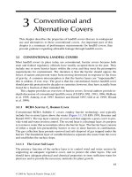
value can be obtained from Figure VII.2.A.
Figure VII.2.A Average specific heats of air.
Q
DQ C T T T H
DH CT T
sf
ww p c
he
rw
sf sf
pc r
=
−− −
−−
[(. . ) ]
[.()
11 01
11
T
HR
T
HR
T
he
cw
=
+−
100
1
100
©1999 CRC Press LLC
Example VII.2.5 Determine the supplementary fuel requirements
Referring to the remediation project described in Example VII.2.2, an off-gas
stream (Q = 200 scfm) containing 800 ppmV of xylene is to be treated by a
thermal oxidizer with a recuperative heat exchanger. The combustion tem-
perature is set at 1800°F. Determine the flow rate of methane as the supple-
mentary fuel, if required.
Solution:
a. Assuming that the heat recovery is 70% and the temperature of the
waste air from the venting well is 65°F, the temperature of the waste
air after the heat exchanger, T
he
, can be found from Eq. VII.2.9 as
b.The average specific heat can be read from Figure VII.2.A as 0.266
Btu/lb-°F at 1800°F.
c. The heat content of the waste gas is 55.6 Btu/lb, as determined in
Example VII.2.2.
d. The flow rate of the supplementary fuel can be estimated by using
Eq. VII.2.8 as
VII.2.6 Volume of combustion chamber
The total influent flow to an incinerator is the sum of the waste air, dilution
air (and/or the auxiliary air), and the supplementary fuel, and it can be
determined by the following equation:
[Eq. VII.2.10]
where Q
inf
= the total influent flow rate, scfm.
In most cases, one can assume that the flow rate of the combined gas
stream, Q
inf
, entering the combustion chamber is approximately equal to the
flue gas leaving the combustion chamber at standard conditions, Q
fg
. The
volume change across the incineration chamber, due to combustion of VOC
T
HR
T
HR
T
he
cw
=
+−
=
+−
=°
100
1
100
70
100
1800 1
70
100
65 1280() () F
Q
DQ C T T T H
DH CT T
sf
ww p c
he
rw
sf sf
pc r
=
−− −
−−
=
−− −
−−
=
[(. . ) ]
[.()]
( . )( ){( . )[ . ( ) . ( ) . )}
( . )[ , ( . )[( . )( )]
.
11 01
11
0 0739 200 0 266 1 1 1800 1280 0 1 77 55 6
0 0408 21 600 1 1 0 266 1800 77
2 21scfm
QQQQ
w
d
sfinf
=++
©1999 CRC Press LLC
and supplementary fuel, is assumed to be small. This is especially true for
dilute VOC streams from soil or groundwater remediation.
The flue gas flow rate of actual conditions can be determined from Eq.
VII.2.1 or from the following equation:
[Eq. VII.2.11]
where Q
fg,a
is the actual flue gas flow rate in acfm.
The volume of the combustion chamber, V
c
, is determined from the
residence time, τ (in sec), and Q
fg,a
by using the following equation:
[Eq. VII.2.12]
The equation is nothing but “residence time = volume ÷ flow rate.” The
factor of 1.05 is a safety factor, which is an industrial practice to account for
minor fluctuations in the flow rate. Table VII.2.B lists the typical thermal
incinerator system design values.
Example VII.2.6 Determine the size of the thermal incinerator
Referring to the remediation project described in Example VII.2.5, an off-gas
stream (Q = 200 scfm) containing 800 ppmV of xylene is to be treated by a
thermal oxidizer with a recuperative heat exchanger. The combustion tem-
perature is set at 1800°F to achieve a destruction efficiency of 99% or higher.
Determine the size of the thermal incinerator.
Solution:
a. Use Eq. VII.2.10 to determine the flue gas flow rate at standard con-
ditions:
Table VII.2.B Typical Thermal Incinerator System Design Values
Required
destruction
efficiency (%)
Non-halogenated compounds Halogenated compounds
Combustion
temperature
(°F)
Residence
time
(sec)
Combustion
temperature
(°F)
Residence
time
(sec)
98 1600 0.75 1800 1.0
99 1800 0.75 2000 1.0
From U.S. EPA, Control Technologies for Hazardous Air Pollutants, EPA/625/6-
91/014, U.S. EPA, Washington, DC, 1991.
T
Q
T
fg a fg
c
fg
c
,
=
+
+
=
+
460
77 460
460
537
V
Q
c
fg a
=
×
,
.
60
105τ
©1999 CRC Press LLC
Q
fg
~ Q
inf
= Q
w
+ Q
d
+ Q
sf
= 200 + 0 + 2.21 = 202.2 scfm
b. Use Eq. VII.2.11 to determine the flue gas flow rate at actual conditions
c.From Table VII.2.B, the required residence time is one second. Use Eq.
VII.2.12 to determine the size of the combustion chamber as
VII.3 Catalytic incineration
Catalytic incineration, also known as catalytic oxidation, is another com-
monly applied combustion technology for treating VOC-laden air. With pres-
ence of a precious or base metal catalyst, the combustion temperature is
normally between 600 and 1200°F, much lower than that of a direct thermal
incineration system.
For catalytic oxidation, the “three T’s” (temperature, residence time, and
turbulence) are still the important design parameters. In addition, the type
of catalyst has a significant effect on the system performance and cost.
VII.3.1 Dilution air
The concentration of flammable vapors to a catalytic incinerator is gen-
erally limited to 10 Btu/scf or 135 Btu/lb (equivalent to 20% LEL for most
VOCs), which is lower than that for direct incineration. It is due to the fact
that higher VOC concentrations may generate too much heat upon combus-
tion to deactivate the catalyst. Therefore, dilution air must be used to lower
the contaminant concentration to below 20% of its LEL.
When dilution is required, the volumetric flow rate of the dilution air
can be found as
[Eq. VII.3.1]
where Q
dilution
= required dilution air, scfm, Q
w
= waste air stream to be treated,
scfm, H
w
= heat content of the waste air stream, Btu/scf (or Btu/lb), and H
i
= heat content of the desired influent entering the treatment system, Btu/scf
(or Btu/lb).
T
acfm
fg a fg
c
,
(.)=
+
=
+
=
460
537
202 2
1800 460
537
851
V
Q
c
fg a
=
×=
×=
,
.
.
() . .
60
105
202 2
60
110535τ ft
3
Q
H
H
Q
dilution
w
i
w
=−
1
©1999 CRC Press LLC
Example VII.3.1 Determine the dilution air requirement
Referring to the remediation project described in Example VII.2.3, an off-gas
stream (Q = 200 scfm) containing 800 ppmV of xylene is to be treated by a
catalytic incinerator with a recuperative heat exchanger. Determine the
required dilution air flow rate, if needed.
Solution:
The heating value of the off-gas has been determined as 11.6 Btu/scf or 160
Btu/lb in Example VII.2.3A, which exceeds the 10 Btu/scf or 135 Btu/lb
limit. Thus, air dilution is required, and the dilution air flow rate can be
determined by using Eq. VII.3.1 as
Discussion. For the same off-gas, 800 ppmV of xylene, air dilution is
required for catalytic incineration but not required for direct incineration.
VII.3.2 Supplementary heat requirements
For catalytic incineration of off-gases from soil/groundwater remediation,
supplementary heat is often provided by electrical heaters. If natural gas is
used, one can use Eq. VII.2.8 to determine the supplementary fuel flow rate.
The following two equations should be applied first to estimate the temper-
ature of the flue gas, T
out
, which would achieve the desired destruction effi-
ciency without damaging the catalyst. It can be estimated from the temper-
ature of the waste gas leaving the heat exchanger (and before entering the
catalyst bed), T
in
, and the heat content of the gas:
[Eq. VII.3.2]
On the other hand, the equation can be used to determine the required
influent temperature to achieve a desired temperature in the catalyst bed:
[Eq. VII.3.3]
where H
w
is the heat content of the waste air stream in Btu/scf. These two
equations assume a 50°F temperature increase for every 1 Btu/scf of heat
content in the influent air to the catalyst bed.
Example VII.3.2 Estimate the temperature of the catalyst bed
Referring to the remediation project described in Example VII.3.1, an off-gas
stream (Q = 200 scfm) containing 800 ppmV of xylene is to be treated by a
Q
H
H
Q
dilution
w
i
w
=−
=−
=1
160
135
1 200 37( ) scf
m
TT H
out in w
=+50
TT H
in out w
=−50
©1999 CRC Press LLC
catalytic incinerator with a recuperative heat exchanger. After the heat
exchanger, the temperature of the diluted waste gas is 550°F. Estimate the
temperature of the catalyst bed.
Solution:
After air dilution, heat content of the diluted waste gas is 10 Btu/scf. Use
Eq. VII.3.2 to estimate the temperature of the catalyst bed:
T
out
= T
in
+ 50H
w
= 550 + (50)(10) = 1050°F
Discussion. The calculated temperature, 1050°F, falls in the typical
temperature range for catalyst beds, i.e., 900 to 1200°F.
VII.3.3 Volume of the catalyst bed
The total influent flow to a catalyst bed is the sum of the waste air, dilution
air (and/or the auxiliary air), and the supplementary fuel, and it can be
determined by the following equation:
[Eq. VII.3.4]
where Q
inf
= the total influent flow rate, scfm.
In most of the cases, one can assume that the flow rate of the combined
gas stream, Q
inf
, entering the catalyst is approximately equal to the flue gas
leaving the catalyst at standard conditions, Q
fg
. The flue gas flow rate of
actual conditions can be determined from Eq. VII.2.1 or from the equation
below:
[Eq. VII.3.5]
where Q
fg,a
is the actual flue gas flow rate in acfm.
Because of the short residence time in the catalyst bed, space velocity is
commonly used to relate the volumetric air flow rate and the volume of the
catalyst bed. The space velocity is defined as the volumetric flow rate of the
VOC-laden air entering the catalyst bed divided by the volume of the catalyst
bed. It is the inverse of residence time. Table VII.3.A provides the typical
design parameters for catalytic incinerators. It should be noted here that the
flow rate used in the space velocity calculation is based on the influent gas
flow rate at standard conditions, not that of the catalyst bed or the bed
effluent.
The size of the catalyst can be determined by
QQQQ
w
d
sf
inf
=++
T
Q
T
fg a fg
c
fg
c
,
=
+
+
=
+
460
77 460
460
537
©1999 CRC Press LLC
[Eq. VII.3.6]
where V
cat
= volume of the catalyst bed, ft
3
, Q
inf
= the total influent flow rate
to the catalyst bed, in scfm, and SV = space velocity, hr
–1
.
Example VII.3.3 Determine the size of the catalyst bed
Referring to the remediation project described in Example VII.3.1, an off-gas
stream (Q = 200 scfm) containing 800 ppmV of xylene is to be treated by a
catalytic incinerator with a recuperative heat exchanger. The design space
velocity is 12,000 hr
–1
. Determine the size of the catalyst bed.
Solution:
a. Use Eq. VII.3.4 to determine the flue gas flow rate at standard condi-
tions:
Q
fg
~ Q
inf
= Q
w
+ Q
d
+ Q
sf
= 200 + 37 + 0 = 237 scfm
b. With a space velocity of 12,000 hr
–1
, use Eq. VII.2.12 to determine the
size of the catalyst bed:
Discussion. The size of the catalyst, 1.2 ft
3
, is smaller than the volume
of the combustion chamber for direct incineration, 3.5 ft
3
.
VII.4 Internal combustion engines
The internal combustion (IC) engine of a conventional automobile or truck
can be modified and incorporated in a control system to treat VOC-laden
air. The IC engine is used as a thermal incinerator, and the physical difference
between the IC engine units and the thermal incinerators is mainly in the
geometry of the combustion chamber.
Table VII.3.A Typical Design Parameters for Catalytic Incineration
Desired
destruction
efficiency (%)
Temperature
at catalyst
bed inlet (°F)
Temperature
at catalyst
bed outlet (°F)
Space Velocity (hr
–1
)
Base metal Precious metal
95 600 1000–1200 10,000–15,000 30,000–40,000
From U.S. EPA, Control Technologies for Hazardous Air Pollutants, EPA/625/6-91/014, U.S.
EPA, Washington, DC, 1991.
V
Q
SV
cat
=
60
inf
V
Q
SV
cat
== =
60
60 237
12 000
12
inf
()( )
,
.ft
3
©1999 CRC Press LLC
VII.4.1 Sizing criteria/application rates
The sizing of an IC engine device is based on the volumetric flow rate of the
VOC-laden air to be treated. One vendor reports that their IC engine unit
can handle up to 80 cfm of VOC-laden air, while the other reports that their
unit can accommodate 100 to 200 scfm of influent gas (depending on the
VOC concentrations) for every 300 in
3
of engine capacity.
2
Conservatively
speaking, a typical IC engine should not handle more than 100 cfm of VOC-
laden air. For a higher flow rate, a treatment system with a few IC engines
in parallel would be needed.
Example VII.4.1 Determine the number of IC engines needed
Referring to the remediation project described in Example VII.3.1, an off-gas
stream (Q = 200 scfm) containing 800 ppmV of xylene is to be treated by IC
engines. Determine the number of IC engines needed for this project.
Solution:
The average off-gas flow rate is 200 scfm, and a typical IC engine can only
handle 100 scfm as the maximum. Therefore, a minimum of two IC engines
in parallel should be used in this project.
VII.5 Soil beds/biofilters
Biofiltration is an emerging technology for treating VOC-laden air. In biofil-
tration, the VOC-laden air is vented through a biologically active soil
medium where VOCs are biodegraded. The temperature and moisture of
the air stream and biofilter bed are critical in design considerations.
VII.5.1 Design criteria
Biofiltration is cost effective for large volume air streams with relatively low
concentrations (<1000 ppmV as methane). Maximum influent VOC concen-
trations have been found to be 3000 to 5000 mg/m
3
. For optimum efficiency,
the waste air stream should at 20 to 40°C and 95% relative humidity. The
filter material should be maintained at 40 to 60% moisture by weight and a
pH between 7 and 8. Typical biofilter systems have been designed to treat
1000 to 150,000 m
3
/hr waste air with a cross-sectional area of 10 to 2000 m
2
.
The typical depth of biofilter media is three to four feet.
2
The typical surface
loading rate is 100 m
3
/hr of waste air stream per m
2
filter cross-sectional
area. The required cross-sectional area of the biofilter (A
filter
) can be deter-
mined as
[Eq. VII.5.1]A
biofilter
=
air flow rate
surface loading rate