Engineering - Materials Selection in Mechanical Design Part 8 pps
Bạn đang xem bản rút gọn của tài liệu. Xem và tải ngay bản đầy đủ của tài liệu tại đây (753.07 KB, 16 trang )
8.1 Introduction and synopsis
This chapter, like Chapter 6, is a collection of case studies. They illustrate the use of material indices
which include shape. Remember: they are only necessary for the restricted class of problems in
which ~ection shape directly influences performance, thatis, when the prime function of a component
is to carry loads which cause it to bend, twist or buckle. And even then they are needed only when
the shape is itself a variable, that is, when different materials come in different shapes. When all
candidate-materials can be made to the same shapes, the indices reduce to those of Chapter 6.
Indices which include shape provide a tool for optimizing the co-selection of material-and-shape.
The important ones are summarized in Table 8.1. Many were derived in Chapter 7; the others are
derived here. Minimizing cost instead of weight is achieved by replacing density p by CmP, where
C m is the cost per kilogram.
The selection procedure is, first, to identify candidate-materials and the section shapes in which
each is available, or could be made. The relevant material properties* and shape factors for each are
tabulated. The best material-and-shape combination is that with the greatest value of the appropriate
index. The same information can be plotted onto Materials Selection Charts, allowing a graphical
solution to the problem -one which often suggests further possibilities.
The method has other uses. It gives insight into the way in which natural materials -many of
which are very efficient -have evolved. Bamboo is an example: it has both internal or microscopic
shape and a tubular, macroscopic shape, giving it very attractive properties. This and other aspects
are brought out in the case studies which now follow.
8.2 Spars for man-powered planes
Most engineering dasign is a difficult compromise: it must meet, as best it can, the conflicting
demands of multiple objectives and constraints. But in designing a spar for a man-powered plane
the objective is simple: the spar must be as light as possible, and still be stiff enough to maintain
the aerodynamic efficiency of the wings (Table 8.2). Strength, safety, even cost, hardly matter when
records are to be broken. The plane (Figure 8.1) has two main spars: the transverse spar supporting
the wings, and the longitudinal spar carrying the tail assembly. Both are loaded primarily in bending
(torsion cannot, in reality, be neglected, although we shall do so here).
Some 60 man-powered planes have flown successfully. Planes of the first generation were built
of balsa wood and spruce. The second generation relied on aluminium tubing for the load-bearing
* The material properties used in this chapter are taken from the CMS compilation published by Granta Design, Trump-
ington Mews, 40B High Street, Trumpington CB2 2LS, UK.
Shape
-
case studies
195
Table
8.1
Examples
of
indices which include shape
(a)
Stiffness and strength-limited design at minimum weight (or cost*)
Component shape, loading and constraints Stifiess-limited Strength-limited
Tie
(tensile member)
design design
Uf
E
P P
-
Load, stiffness and length specified, section-area free
-
Beam
(loaded in bending)
Loaded externally
or
by self weight, stiffness, strength and length
Torsion bar
or
tube
Loaded externally
,
stiffness, strength and length specified, section
Column
(compression strut)
Collapse load by buckling or plastic crushing and length specified,
(GO
l’*
(4LBf.f
)*I3
(@;w*
(4U.f
)*I3
(W)‘l2
“i
specified, section area free
P P
area free
P P
section area free
P
P
*For cost, replace
p
by
C,p
in the indices.
(a) Springs, specified energy storage at minimum volume
or
weight
(or
cost*)
Component shape, loading and constraints Flexural springs Torsion springs
Spring
Specified energy storage, volume to be minimized
Spring
Specified energy storage, mass to be minimized
*For cost, replace
p
by C,p
in the indices.
(&bf
)*
(&f
)*
(&f
l2
(&d2
GE
GE
4FP
@EP
Table
8.2
Design requirements for wing spars
Function
Wing spar
Objective Minimum mass
Constraints
(a)
Specified stiffness
(b) Length specified
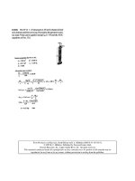
Fig.
8.1
The loading on a man-powered plane is carried
by
two spars, one spanning the wings and the
other linking the wings to the tail. Both are designed for stiffness at minimum weight.
196
Materials Selection in Mechanical Design
structure. The present, third, generation uses carbon-fibre/epoxy spars, moulded to appropriate
shapes. How has this evolution come about? And how much further can it go?
The model and the selection
We seek a material-and-shape combination that minimizes weight for a given bending stiffness. The
index to be maximized, read from Table
8.1,
is
Data for four materials are assembled in Table
8.3.
If all have the same shape,
MI
reduces to the
familiar
E’/2/p
and the ranking
is
that of the second last column. Balsa and spruce are significantly
better than the competition. Woods are extraordinarily efficient. That is why model aircraft builders
use them now and the builders of real aircraft relied so heavily on them in the past.
The effect of shaping the section, to a rectangle for the woods, to a box-section for aluminium
and CFRP, gives the results
in
the last column. (The shape factors listed here are typical of commer-
cially available sections, and are well below the maximum for each material.) Aluminium is now
marginally better than the woods; CFRP is best of all.
The same information is shown graphically in Figure 8.2, using the method of Chapter
7.
Each
shape is treated as a new material with modulus
E*
=
E/@$
and
p*
=
p/@i.
The values of
E*
and
p*
are plotted on the chart. The superiority of both the aluminium tubing with
@
=
20
and the
CFRP box-sections with
@
=
10
are clearly demonstrated.
Postscript
Why is wood so good? With no shape it does as well or better than heavily-shaped steel. It is
because wood
is
shaped: its cellular structure gives
it
internal shape (see p. 182), increasing the
performance of the material in bending; it
is
nature’s answer
to
the I-beam. Bamboo, uniquely,
combines microscopic and macroscoptic shape (see next section).
But the technology of drawing thin-walled aluminium tubes has improved. Aluminium itself is
stiffer than balsa or spruce, but it is also nearly
10
times denser, and that makes it, as a solid, far less
attractive. As a tube, though, it can be given a shape factor which cannot be reproduced in wood.
An aluminium tube with a shape factor
4;
=
r/t
=
20 is as good
as
solid balsa or spruce; one with
a thinner wall is better
-
a fact that did not escape the designers of the second generation of man-
powered planes. There is
a
limit, of course: tubes that are too thin will kink (a local elastic buckling);
as shown in Chapter
7,
this sets an upper limit to the shape factor for aluminium at about
40.
Table
8.3
Materials for wing spars
Muterial Modulus
E
Density
p
Shape factor Index Index
M;
(GPO)
(Mg/m3
)
4;
E’/’lp
((GPa)‘I2/Mg/m3)
Balsa 4.2-5.2 0.17-0.24 1-2
11
11-15
Steel 200- 2 10
7.82 -7.84 25-30
1.8
9-
10
AI
7075
T6
71 -73 2.8 -2.82
15-25
3 12-15
CFRP
100- 160 1.5-1.6 10- 15
7
23-28
Spruce
9.8-
11.9
0.36-0.44 1-2
9
9-
12
*The range
of
values
of
the indices
are
based on means
of
the material properties and corresponds
to
the range
of
values
of
(b;.
Shape
-
case studies
197
Fig.
8.2
The materials-and-shapes for wing-spars, plotted on the modulus-density chart.
A
spar made
of
CFRP
with a shape factor
of 10
outperforms spars made of aluminium
(4
=
20)
and wood
(4
=
1
).
The last
20
years has seen further development: carbon-fibre technology has reached the market
place.
As
a solid beam, carbon-fibre reinforced polymer laminates are nearly as efficient as spruce.
Add a bit
of
shape (Table
8.3)
and they are better than any of the competing materials. Contemporary
composite technology allows shape factors of at least
10,
and that gives an increase in performance
that
-
despite the
cost
-
is
attractive to plane builders.
Further reading: man-powered flight
Drela, M. and Langford, J.D.
(1985)
Man-powered
flight,
Scient&-
American,
January issue, p.
122.
198
Materials Selection in Mechanical Design
Related case studies
Case Study
8.3:
Forks for a racing bicycle
Case Study
8.4:
Floor joists
8.3
Forks
for
a racing bicycle
The first consideration in bicycle design (Figure
8.3)
is strength. Stiffness matters, of course, but
the initial design criterion is that the frame and forks should not yield or fracture in normal use.
The loading on the forks is predominantly
bending.
If
the bicycle is for racing, then the mass is a
primary consideration: the forks should be as light as possible. What is the best choice of material
and shape? Table
8.4
lists the design requirements.
The model and the selection
We model the forks as beams of length
l
which must carry a maximum load
P
(both fixed by
the design) without plastic collapse or fracture. The forks are tubular, of radius
r
and fixed wall-
thickness
t.
The mass
is
to be minimized. The fork is a light, strong beam. Further details of load
and geometry are unnecessary: the best material and shape, read from Table
8.1,
is that with the
Fig.
8.3
The bicycle. The forks are loaded in bending. The lightest forks which will not collapse plastically
under a specified design load are those made of the material and shape with the greatest value of
(&n)2’3/P.
Table
8.4
Design requirements for bicycle forks
Function Bicycle
forks
Objective Minimize mass
Constraints (a)
Must
not
fail
under design loads
-
a
strength constraint
(b)
Length specified
Shape
-
case studies
199
Table
8.5
Material for bicycle
forks
Mate rial
Strength
of
Density
p
Shape factor Index Index M;
(MPa)
(
Mgh'
)
44
/
p
((MPa)2f3/Mg/m3)
Spruce (Norwegian) 70-80 0.46-0.56
1-1.5
36
36-50
Bamboo
80-160
0.6-0.8 2.4-2.8
(33) 59-65
Steel (Reynolds 531) 770-990
7.82-7.83
7-8
12
44-48
Alu (6061 -T6)
240-260
2.69-2.71
5.5-6.3
15
47-51
Titanium 6-4
930-980 4.42-4.43
5.5-6.3 22 69-75
Magnesium AZ 91 160-
170
1.80-
1.81
4-4.5 17 42-46
CFRP 300-450
1.5-
1.6 4-4.5 33
83-90
*The range
of
values
of
the
indices are based on means
of
the material
properties
and corresponds
to
the range
of
values
of
I&.
greatest value of
Table
8.5
lists seven candidate materials. Solid spruce or bamboo are remarkably efficient; without
shape (second last column) they are better than any of the others. Bamboo is special because it grows
as a hollow tube with
a
macroscopic shape factor between
3
and
5,
giving it a bending strength
which is much higher than solid spruce
(last
column). When shape is added
to
the other materials,
however, the ranking changes. The shape factors listed in the table are achievable using normal
production methods. Steel is good; CFRP is better; Titanium
6-4
is better still. In strength-limited
applications magnesium is poor despite its low density.
f
Postscript
Bicycles have been made of all seven of the materials listed in the table
-
you can still buy
bicycles made of six of them (the magnesium bicycle was discontinued in
1997).
Early bicy-
cles were made of wood; present-day racing bicycles of steel, aluminium or CFRP, sometimes
interleaving the carbon fibres with layers of
glass
or Kevlar
to
improve the fracture-resistance.
Mountain bicycles, for which strength and impact resistance are particularly important, have steel
or titanium forks.
The reader may be perturbed by the cavalier manner in which theory for
a
straight beam with
an end load acting normal
to
it is applied
to
a
curved beam loaded
at
an
acute angle.
No
alarm is
necessary. When (as explained in Chapter
5)
the variables describing the functional requirements
(F),
the geometry
(G)
and the materials
(M)
in the performance equation are separable, the details
of
loading and geometry affect the terms
F
and
G
but not
M.
This is an example: beam curvature
and angle
of
application of load do not change the material index, which depends only
on
the design
requirement of strength in bending at minimum weight.
Further reading: bicycle design
Sharp, A.
(1
993)
Bicycles and Tricycles, an Elementary Treatise on their Design and Construction,
The MIT
Watson,
R.
and Gray, M. (1978)
The Penguin Book of the Bicycle,
Penguin
Books,
Harmondsworth.
Whitt, F.R. and Wilson, D.G. (1985)
Bicycling Science,
2nd edition, The MIT Press, Cambridge, MA.
Wilson, D.G. (1986)
A
short history
of
human powered vehicles,
The American Scientist,
74,
350.
Press, Cambridge, MA.
200
Materials Selection in Mechanical Design
Related case studies
Case Study
8.2:
Wing spars for man powered planes
Case Study
8.4:
Floor joists: wood or steel?
8.4
Floor
joists:
wood
or
steel?
Floors are supported on
joists:
beams which span the space between the walls. Let us suppose that a
joist is required to support a specified bending load (the ‘floor loading’) without sagging excessively
or failing; and it must be cheap. Traditionally, joists are made
of
wood with a rectangular section
of aspect ratio
2:
1,
giving an elastic shape factor (Table
7.2)
of
4;
=
2.1.
But steel, shaped to an
I-section, could be used instead (Figure
8.5).
Standard steel I-section joists have shape factors in
the range
15
5
4;
5
25
(special I- sections can have much larger values). Are steel I-joists a better
choice than wooden ones? Table
8.6
summarizes the design requirements.
Fig.
8.4
The cross-section of a typical bamboo cane. The tubular shape shown here gives ‘natural’
shape factors of
4;
=
3.3
and
4&
=
2.6.
Because of this (and good torsional shape factors also) it
is widely used for oars, masts, scaffolding and construction. Several bamboo bicycles have been
marketed.
Fig.
8.5
The cross-sections
of
a wooden beam
(4;
=
2)
and
a
steel I-beam
(4;
=
10).
The values
of
4
are calculated from the ratios of dimensions of each beam, using the formulae of Table
7.2.
Table
8.6
Design requirements for floor joists
Function Floor joist
Objective Minimum material cost
Constraints
(a)
Length specified
(b)
Minimum stiffness specified
(c) Minimum strength specified
Shape
-
case studies
201
The model and the selection
Consider stiffness first. The cheapest beam, for a given stiffness, is that with the largest value of
the index (read from Table
8.1
with
p
replaced by
C,p
to minimize cost):
Data for the modulus
E,
the density
p,
the material cost
C,n
and the shape factor
4;
are listed in
Table
8.7,
together with the values of the index
MI
with and without shape. The steel beam with
4;
=
25
has a slightly larger value
MI
than wood, meaning that it is a little cheaper for the same
stiffness.
But what about strength? The best choice for a light beam of specified strength is that which
maximizes the material index:
f
The quantities of failure strength
of,
shape factor
dB
and index
M3
are also given
in
the table.
Wood performs better than even the most efficient steel I-beam.
As
explained in Chapter
7,
a material with a modulus
E
and cost per unit volume
C,p,
when
shaped, behaves in bending like a material with modulus
E*
=
E/@;
and cost
(C,p)*
=
C,,,p/@i.
Figure
8.6
shows the
E-C,p
chart with data for the wooden joists and the steel I-beams plotted
onto it. The heavy broken line shows the material index
MI
=
(@;E)1’2/C,p,
positioned to leave
a small subset of materials above it. Woods with a solid circular section
(4;
=
1)
lie comfortably
above the line; solid steel lies far below it. Introducing the shape factors moves the wood slightly
(the shift is not shown) but moves the steel a lot, putting
it
in
a position where it performs
as
well
as wood.
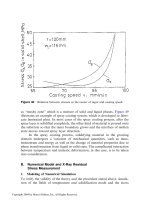
Strength is compared in a similar way in Figure
8.7.
It shows the
of
-C,,,p
chart. The heavy
broken line, this time, is the index
M3
=
(#Bf~rf)*/~/C,,p,
again positioned just below wood. Intro-
ducing shape shifts the steel as shown, and this time it does not do
so
well: even with the largest
shape factor
(4Bf
=
IO)
steel performs less well than wood. Both conclusions are exactly the same
as those of Table
8.7.
Table
8.7
Materials
for
floor
joists
Property Wood (pine) Steel (standard)
Density (Mg/m3)
Flexural modulus (GPa)
Failure strength
-
MOR
(MPa)
Material cost
($/kg)
4;
4i
E
‘
1’
IC,,,
p
(GPa) ‘/*/(k$/m3
)*
a:/3/C,p
(MPa)2/3/(k$/m3)*
MI
(GPa)’/’/(k$/m’
)*
Mz
(MPa)’i3/(k$/m3)*
0.52-0.64
9.8- 11.9
56-70
0.8-
1
.O
2.0-2.2
1.6- 1.8
6.3
30
8.9-9.3
41
-44
7.9-7.9
1
208 -2 12
350-360
0.6-0.7
15-25
5.5-7.1
2.8
9.7
10.8- 14.0
30-36
*The range
of
values
of
the indices are based on means
of
the material properties
and corresponds
to
the range
of
values
of
@;.
202
Materials Selection in Mechanical Design
Fig.
8.6
A
comparison
of
light, stiff beams. The heavy broken line shows the material index
MI
=
5
(GPa)’/’/(Mg/rn3). Steel I-beams are slightly more efficient than wooden joists.
Postscript
So
the conclusion: as far as performance per unit material-cost is concerned, there
is
not much
to choose between the standard wood and the standard steel sections used for joists. As a general
statement, this is no surprise
-
if one were much better than the other, the other would no longer
exist. But
-
looking
a
little deeper
-
wood dominates certain market sectors, steel dominates
others. Why?
Wood is indigenous
to
some countries, and grows locally; steel has to come further, with associ-
ated transport costs. Assembling wood structures is easier than those of steel; it
is
more forgiving
Shape
-
case studies
203
Fig.
8.7
A
comparison
of
light, strong beams. The heavy broken line shows the material index
M2
=
25(MPa)213/(Mg/m3). Steel I-beams are less efficient than wooden joists.
of
mismatches of dimensions, it can be trimmed on site,
you
can hammer nails into
it
anywhere. It
is
a
user-friendly material.
But wood is a variable material, and, like
us,
is vulnerable
to
the ravishes
of
time, prey
to
savage fungi, insects and small mammals. The problems
so
created in a small building
-
family
home, say
-
are easily overcome, but in a large commercial building
-
an office block, for
instance
-
they create greater risks, and are harder to
fix.
Here, steel wins.
Further
reading
Cowan,
H.J.
and
Smith,
P.R.
(1988)
The Science and Technology
of
Building Mutericrls,
Van Nostrand Reinhold,
New
York.
204
Materials Selection in Mechanical Design
Related case studies
Case Study 8.2: Spars for man-powered planes
Case Study
8.3:
Forks for a racing bicycle
8.5
Increasing the stiffness
of
steel sheet
How could you make steel sheet stiffer? There are many reasons you might wish to do
so.
The most
obvious: to enable stiffness-limited sheet structures to be lighter than they are now; to allow panels
to carry larger compressive loads without buckling; and to raise the natural vibration frequencies
of sheet structures. Bending stiffness is proportional to
EZ
(E
is Young’s modulus,
I
is the second
moment of area of the sheet, equal to t3/12 per unit width). There is nothing much you can do to
change the modulus of steel, which is always close to 210GPa. But you can add a bit of shape.
So
consider the design brief of Table
8.8.
The model
The age-old way to make sheet steel stiffer is to corrugate it, giving it a roughly sinusoidal profile.
The corrugations increase the second moment
of
area
of
the sheet about an axis normal to the
corrugations themselves. The resistance to bending in one direction is thereby increased, but in the
cross-direction it is not changed at all.
Corrugations are the clue, but
-
to be useful
-
they must stiffen the sheet in all directions,
not just one.
A
hexagonal grid of dimple (Figure 8.8) achieves this. There is now no direction of
bending that is not dimpled. The dimples need not be hexagons; any pattern arranged in such a way
that you cannot draw a straight line across it without intersecting dimples will do. But hexagons
are probably about the best.
Dimples improve all the section-properties of a sheet, in a way that can be estimated as follows.
Consider an idealized cross-section as in the lower part of Figure
8.8,
which shows the section
A-A,
enlarged.
As
before, we define the shape factor as the ratio of the stiffness of the dimpled
sheet to that of the flat sheet from which
it
originated. The second moment
of
area
of
the flat
sheet is
t3
I
A
(8.5)
O-
12
That
of
the dimpled sheet with amplitude
a
is
1
12
I
RZ
-(2a
+
t)%t
Table
8.8
Design requirements for stiffened steel sheet
Function
Objective
Constraints
Steel sheet for stiffness-limited structures
Maximize bending stiffness of sheet
(a) Profile limited to a maximum deviation
f5
times the
sheet thickness from flatness
(b)
Cheap to manufacture
Shape
-
case studies
205
Fig.
8.8
A
sheet with a profile
of
adjacent hexagonal dimples which increases its bending stiffness and
strength. Shape factors for the section
A-A
are calculated in the text. Those along other trajectories are
lower but still significantly greater than
1.
giving
a
shape factor, defined
as
before as the ratio of the stiffness of the sheet before and after
corrugating (see the Appendix of Chapter
7):
I
(2a
+
t)2
I
0
t2
@r,=-=
(8.7)
Note that the shape factor has the value unity when the amplitude is zero, but increases as the
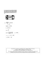
amplitude increases. The equivalent shape factor for failure in bending
is
(8.8)
z
0
t
These equations predict large gains in stiffness and strength. The reality is a little less rosy. This
is because, while all cross-sections of the sheet are dimpled, only those which cut through the peaks
of the dimples have an amplitude equal to the peak height
(all
others have less) and, even among
these, only some have adjacent dimples; the section
B-B,
for example does not. Despite this, and
limits set by the onset of local buckling, the gain is real.
&-=-
z
(2a
+t)
Postscript
Dimpling can be applied to most rolled-sheet products. It is done by making the final roll-pass
through mating rolls with meshing dimples, adding little
to
the cost. It is most commonly applied to
sheet steel. Here it finds applications
in
the automobile industry including bumper armatures, seat
frames, side impact bars: the material offers weight saving without
loss
of mechanical performance.
Stiffening sheet also raises its natural vibration frequencies, making them harder to excite, thus
helping to suppress vibration in panels.
206
Materials Selection in Mechanical Design
But a final word of warning: stiffening the sheet may change its failure mechanism. Flat sheet
yields when bent; dimpled sheet, if thin, could fail by a local buckling mode.
It
is this which
ultimately limits the useful extent of dimpling.
Further reading
Fletcher,
M.
(1998)
Cold-rolled dimples improve gauge strength,
Eureka,
May,
p.
28.
8.6
Ultra-eff icient springs
Springs, we deduced in Case Study
6.7,
store energy. They are best made of a material with a high
value
of
a;/E,
or, if mass
is
more important than volume, then of
a;/pE.
Springs can be made
more efficient still by shaping their section. Just how much more is revealed below.
We take as a measure
of
performance the energy stored per unit volume
of
solid of which the
spring is made; we wish to maximize this energy. Energy per unit weight and per unit cost are
maximized by similar procedures (Table 8.9).
The model
Consider a leaf spring first (Figure 8.9(a)).
A
leaf spring is an elastically bent beam. The energy
stored in a bent beam, loaded by a force
F,
is
1
F2
u=
(8.9)
where
SB,
the bending stiffness
of
the spring, is given by equation
(7.1),
or, after replacing
I
by
@$,
by equation
(7.25),
which, repeated, is
2
SB
(8.10)
C1
A*
SB
=
G@ioE
Table
8.9
Design requirements for ultra-efficient springs
Function Material-efficient spring
Objective
Constraint
Maximum stored energy per unit volume (or mass,
or
cost)
Must remain elastic under design
loads
Fig.
8.9
Hollow
springs use material more efficiently than solid springs. Best in bending is the hollow
elliptical section; best in torsion is the tube.
Shape
-
case
studies
207
The force
F
in equation
(8.9)
is limited by the onset
of
yield; its maximum value is
(8.11)
(The constants
C1
and
Cz
are tabulated
in
Appendix A Section A3 and
A4).
Assembling these gives
the maximum energy the spring can store:
(8.12)
where
V
=
At
is the volume of solid in the spring. The best material and shape for the spring
-
the
one that uses the least material
-
is that with the greatest value
of
the quantity
(8.13)
For
a
fixed section shape, the ratio involving the two
@s
is a constant: then the best choice of material
is that with the greatest value of
":/E
-
the same result
as
before. When shape is a variable, the
most efficient shapes are those with large
(@i)2/@$.
Values for these ratios are tabulated for common
section shapes
in
Table
8.10;
hollow elliptical sections are up to three times more efficient than solid
shapes.
Torsion bars and helical springs are loaded in torsion (Figure 8.9(b)). The same calculation, but
using equations
(7.28) and (7.33),
in
the way that equations
(8.10)
and
(8.1
1)
were used, gives
The most efficient material and shape for a torsional spring is that with the largest value of
7
(8.14)
(8.15)
(where
G
has been replaced by
3El8).
The criteria are the same: when shape is not a variable, the
best torsion-bar materials are those with high values of
CT;/E.
Table 8.10 shows that the best shapes
are hollow tubes, which have a ratio of
(@{)2/@F
which is twice that
of
a solid cylinder; all other
shapes are less efficient. Springs which store the maximum energy per unit weight (instead of unit
volume) are selected with indices given by replacing
E
by
Ep
in equations (8.13) and (8.15). For
maximum energy per unit cost, replace
Ep
by
EC,p
where
C,,
is the cost per kg.
Postscript
Hollow springs are common in vibrating and oscillating devices and for instruments
in
which
inertial forces must be minimized. The hollow elliptical section is widely used for springs loaded
in bending; the hollow tube
for
those loaded
in
torsion. More about this problem can be found
in
the classic paper by Boiten.
208
Materials Selection in Mechanical Design
Table
8.10
Shape factors for the efficiency of springs
Shape
-
case
studies
209
Further reading: design
of
efficient springs
Boiten,
R.G.
(1963)
Mechanics
of
instrumentation,
Proc.
I.
Mech. E.,
177,
p.
269.
Related case studies
Case Study
6.9:
Materials for springs
8.7
Summary and conclusions
In designing components which are loaded such that they bend, twist or buckle, the designer has
two groups of variables with which to optimize performance: the
material properties
and the
shape
ofthe section.
The best choice
of
material depends on the shapes in which it is available, or to
which it could potentially be formed. The procedure of Chapter
7
gives
a
method for optimizing
the choice of material and shape.
Its use is illustrated in this chapter. Often the designer has available certain stock materials
in certain shapes. Then that with the greatest value of the appropriate material index
(of
which
a
number were listed in Table
8.1)
maximizes performance. Sometimes sections can be specially
designed; then material properties and design loads determine
a
maximum practical value for the
shape factor above which local buckling leads to failure; again, the procedure gives an optimal
choice of material and shape. Further gains in efficiency are possible by combining microscopic
with macroscopic shape.