Engineering Materials vol 1 Part 6 ppsx
Bạn đang xem bản rút gọn của tài liệu. Xem và tải ngay bản đầy đủ của tài liệu tại đây (942.51 KB, 25 trang )
Continuum
aspects
of
plastic
flow
1
17
I
I
I
I
1
I
c
Fig. 11.7.
Mild
steel
can
be
drawn out a lot before it
fails
by necking.
t
Fig. 11.8.
Aluminium
alloy
en
quickly necks when it
is
drawn out.
I
-
Necking
-
rl;
-/
I
L
-
4
Fig.
1
1.9.
Polythene
forms
a stable neck when
it
is
drawn aut; drawn polyihene
is
very strong.
1
18
Engineering
Materials
1
Aluminium alloy is much less good (Fig.
11.8)
-
it can only be drawn a little before
instabilities form. Pure aluminium is not nearly as bad, but is much too
soft
to use for
most applications.
Polythene shows a kind of necking that does
not
lead to fracture. Figure
11.9
shows
its
u,/E,
curve. At quite low stress
dun
den
-
becomes zero and necking begins. However, the neck never becomes
unstable
-
it
simply grows in length
-
because at high strain the material work-hardens
considerably, and is able to support the increased stress at the reduced cross-section of
the neck. This odd behaviour is caused by the lining up of the polymer chains in the
neck along the direction of the neck
-
and for this sort of reason
drawn
(i.e. 'fully
necked') polymers can be made to be very strong indeed
-
much stronger than the
undrawn polymers.
"n
t
Unstable
necking
Fig.
11
.lo.
Mild
steel
often shows
both
stable and unstable
necks.
Finally, mild steel can sometimes show an instability like that
of
polythene.
If
the
steel
is
annealed, the stress/strain curve looks like that in Fig.
11.10.
A
stable neck,
called
a
Luders Band, forms and propagates (as it did in polythene) without causing
fracture because the strong work-hardening of the later part of the stress/strain curve
prevents this. Liiders Bands are a problem when sheet steel is pressed because they
give lower precision
and
disfigure the pressing.
Further
reading
A.
H.
Cottrell,
The Mechanical Properties
of
Matter,
Wiley,
1964,
Chap.
10.
C.
R.
Calladine,
Engineering Plasticity,
Pergamon Press,
1969.
W.
A.
Backofen,
Deformation Processing,
Addison-Wesley,
1972.
R.
Hill,
The Mathematical Theory
of
Plasticity,
Oxford University Press,
1950.
Chapter
12
Case
studies in yield-limited design
Introduction
We now examine three applications of our understanding of plasticity. The first
(material selection
for
a spring) requires that there be
no plasticity whatever.
The second
(material selection for a pressure vessel) typifies plastic design of a large structure. It is
unrealistic to expect no plasticity: there will always be some, at bolt holes, loading
points, or changes
of
section. The important thing is that yielding should not spread
entirely through any section of the structure
-
that is, that
plasticity must not become
general.
Finally, we examine an instance (the rolling of metal strip) in which yielding is
deliberately induced, to give
large-strain plasticity.
CASE
STUDY
1
:
ELASTIC
DESIGN:
MATERIALS
FOR
SPRINGS
Springs come in many shapes and have many purposes. One thinks of axial springs (a
rubber band, for example), leaf springs, helical springs, spiral springs, torsion bars.
Regardless
of
their shape or use, the best materials for a spring of minimum volume is
that with the greatest value of
u:/E.
Here
E
is Young’s modulus and
uy
the failure
strength
of
the material
of
the spring: its yield strength if ductile, its fracture strength
or modulus of rupture if brittle. Some materials with high values of this quantity are
listed in Table
12.1.
Table
12.1
Materials for springs
Brass (cold-rolled)
638 3.38
5.32
x
770
4.94
6.43
X
Bronze (cold-rolled)
Phosphor bronze
640 3.41 5.33
x
10-3
Beryllium copper
1380
15.9
11.5
x
10-3
Spring
steel
1300 8.45 6.5
x
10-3
lo00
5.0
5.0
x
10-3
61 4 1.9 3.08
x
10-3
]
120
Stainless steel (cold-rolled)
Nimonic (high-temp. spring)
120
Engineering Materials
1
The argument, at its simplest,
is
as follows. The primary function of a spring is that
of storing elastic energy and
-
when required
-
releasing it again. The elastic energy
stored per unit volume in a block of material stressed uniformly to a stress
u
is:
It
is this that we wish to maximise. The spring will be damaged if the stress
u
exceeds the
yield stress or failure stress
a,;
the constraint is
u
5
uy.
So
the maximum energy density
is
Torsion bars and leaf springs are less efficient than axial springs because some of the
material is not fully loaded: the material at the neutral axis, for instance, is not loaded at
all. Consider
-
since we will need the equations in a moment
-
the case of a leaf spring.
The
leaf
spring
Even leaf springs can take many different forms, but all of them are basically elastic
beams loaded in bending.
A
rectangular section elastic beam, simply supported at both
ends, loaded centrally with a force
F,
deflects by an amount
~13
6=-
4Ebt3
(12.1)
ignoring self-weight (Fig. 12.1). Here
1
is the length of the beam,
t
its thickness, bits width,
and
E
is the modulus of the material of which it is made. The elastic energy stored in the
spring, per unit volume, is
(12.2)
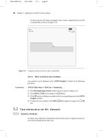
Figure 12.2 shows that the stress in the beam is zero along the neutral axis at its centre,
and is a maximum at the surface, at the mid-point of the beam (because the bending
moment is biggest there). The maximum surface stress is given by
3Fl
2bt2
'
u=-
(12.3)
Fig.
12.1.
A
leaf
spring
under
load
Case studies in yield-limited design
121
Fig.
12.2.
Stresses inside
a
leaf
spring.
Now, to be successful, a spring must not undergo a permanent set during use: it must
always 'spring' back. The condition for this is that the maximum stress (eqn.
(12.3))
always be less than the yield stress:
3F1
3
u!!
(12.4)
Eliminating
t
between this and eqn.
(12.2)
gives
This equation says: if in service a spring has to undergo a given deflection,
6,
under a
force
F,
the ratio of
uy2/E
must be high enough to avoid a permanent set. This is why
we have listed values of
uy2/E
in Table
12.1:
the best springs are made of materials with
high values of this quantity. For this reason spring materials are heavily strengthened
(see Chapter
10):
by solid solution strengthening plus work-hardening (cold-rolled,
single-phase brass and bronze), solid solution and precipitate strengthening (spring
steel), and
so
on. Annealing any spring material removes the work-hardening, and may
cause the precipitate to coarsen (increasing the particle spacing), reducing
uy
and
making the material useless as a spring.
Example:
Springs
for
u
centrifugal
clutch.
Suppose that you are asked to select a
material for
a
spring with the following application in mind. A spring-controlled clutch
like that shown in Fig.
12.3
is designed to transmit
20
horse power at 800rpm; the
,
127
,
Centre
of
gravity
t=2
6
=s
6.35
rnm
Dimensions in rnm
Drum
Block.
Spring
Fig.
12.3.
Leaf
springs in
a
centrifugal clutch
122
Engineering Materials
1
clutch is to begin to pick up load at
600
rpm. The blocks are lined with Ferodo or some
other friction material. When properly adjusted, the maximum deflection of the springs
is to be
6.35
mm (but the friction pads may wear, and larger deflections may occur; this
is a standard problem with springs
-
almost always, they must withstand occasional
extra deflections without losing their sets).
Mechanics
The force on the spring is
F
=
Mrw2
(12.5)
where
M
is the mass of the block,
r
the distance of the centre of gravity of the block
from the centre of rotation, and
w
the angular velocity. The
nef
force the block exerts on
the clutch rim at full speed is
Mr(w3
-
wf)
(12.6)
where
w2
and
w1
correspond to the angular velocities at
800
and
600
rpm (the
net
force
must be zero for
w2
=
wl,
at
600
rpm). The full power transmitted is given by
4psMr(w3
-
w:)
X
distance moved per second by inner rim of clutch at full
speed,
i.e.
power
=
4psMr(o$
-
0:)
X
w2r
(12.7)
where
ps
is the coefficient of static friction.
r
is specified by the design (the clutch
cannot be too big) and
ps
is a constant (partly a property of the clutch-lining material).
Both the power and
w2
and
w1
are specified in eqn.
(12.71,
so
M
is specified also; and
finally the maximum force on the spring, too, is determined by the design from
F
=
Mrw:.
The requirement that this force deflect the beam by only
6.35
mm with the linings
just in contact is what determines the thickness,
t,
of the spring via eqn.
(12.1)
(I
and
b
are fixed by the design).
Metallic materials
for
the clutch
springs
Given the spring dimensions
(t
=
2
mm,
b
=
50
mm,
I
=
127
mm)
and given
6
I
6.35
mm,
all specified by design, which material should we use? Eliminating
F
between eqns
(12.1)
and
(12.4)
gives
uy
66t 6
X
6.35
X
2
E
1’
127
X
127
-
>-=
=
4.7
x
10-3.
(12.8)
Case
studies in yield-limited design
123
F12
F12
-
‘F
Fig.
12.4.
Multi-leaved
springs
(schematic).
As
well as seeking materials with high values of
uy2/E,
we must also ensure that the
material we choose
-
if it is to have the dimensions specified above and also deflect
through
6.35
mm without yielding
-
meets the criterion of eqn. (12.8).
Table 12.1 shows that spring steel, the cheapest material listed, is adequate for this
purpose, but has a worryingly small safety factor to allow for wear
of
the linings. Only
the expensive beryllium-copper alloy, of all the metals shown, would give a significant
safety factor
(wy/E
=
11.5
X
In many designs, the mechanical requirements are such that single springs
of
the
type considered so far would yield even if made from beryllium copper. This
commonly arises in the case
of
suspension springs for vehicles, etc., where both large
6
(‘soft’ suspensions) and large
F
(good load-bearing capacity) are required. The
solution then can be to use multi-leaf springs (Fig.
12.4).
t
can be made
small
to give
large
6
without yield according to
(:)
>
7,
(12.9)
whilst the lost load-carrying capacity resulting from small
t
can be made up by having
several leaves combining
to
support the load.
Non-metallic materials
Finally, materials other than the metals originally listed in Table
12.1
can make
good
springs. Glass, or fused silica, with
uy/E
as large as 58
X
is excellent,
provided
it
operates under protected conditions where it cannot be scratched or suffer impact
loading (it has long been used for galvanometer suspensions). Nylon is
good
-
provided the forces are low
-
having
uy/E
=
22
X
and it is widely used in
household appliances and children’s toys
(you
probably brushed your teeth with little
nylon springs this morning). Leaf springs for heavy trucks are now being made of
CFRP:
the value
of
ay/E
(6
X
is similar to that of spring steel, and the weight
saving compensates for the higher cost.
CFRP
is always worth examining where an
innovative use
of
materials might offer advantages.
124
Engineering Materials
1
CASE STUDY
2:
PLASTIC
DESIGN: MATERIALS FOR
A
PRESSURE VESSEL
We shall now examine material selection for a pressure vessel able to contain a gas at
pressure
p,
first minimising the
weight,
and then the
cost.
We shall seek a design that
will not fail by plastic collapse (i.e. general yield). But we must be cautious: structures
can also fail by
fast fracture,
by
fatigue,
and by
corrosion
superimposed on these other
modes of failure. We shall discuss these in Chapters 13, 15 and 23. Here we shall
assume that plastic collapse is our only problem.
Pressure
vessel
of
minimum
weight
The body of an aircraft, the hull
of
a spacecraft, the fuel tank of a rocket: these are
examples of pressure vessels which must be as light as possible.
Sphere
radius
r
Fig.
12.5.
Thin-walled spherical pressure
vessel.
The stress in the vessel wall (Fig. 12.5) is:
PY
2t
u
=
(12.10)
r,
the radius of the pressure vessel, is fixed by the design. For safety,
u
I
ay/S,
where
S
is the safety factor. The vessel mass is
M
=
4.rrr2tp (12.11)
so
that
M
t
=
4dp
Substituting for
t
in eqn.
(12.8)
we find that
(12.12)
(12.13)
Case studies in yield-limited design
125
Table
12.2
Materials for pressure vessels
Moferial
B
UY
P
(UKf
(US$)
-x
P
103
-x
PP
106
(MN
m-')
(Mg
m-3)
tonne-')
UY
UY
Reinforced concrete
200 2.5
160 (240) 13 2.1
Alloy
steel
(pressure-vessel
steel)
1
000
7.8
500
(750)
7.8 3.9
Aluminium alloy
400
2.7
1100 (1650)
6.8
7.5
Mild
steel
220
7.8
300 (450) 36 10.8
Fi
bregloss
200 1.8
2000 (3000)
9.0
18
CFRP
600 1.5
50,000
(75,000)
2.5
125
From eqn.
(12.11)
we have, for the mass,
M
=
S2npP
-
(1
2.14)
so
that for the lightest vessel we require the smallest value of
(p/a,).
Table
12.2
gives
values of
p/uy
for candidate materials.
By far the lightest pressure vessel is that made of
CFRP.
Aluminium alloy and
pressure-vessel steel come next. Reinforced concrete or mild steel results in a very
heavy vessel.
tY
1
Pressure vessel
of
minimum
cost
If the cost of the material is
f3
UK€(US$)
tonne-' then the material cost of the vessel is
pM
=
constantp(:).
(1
2.15)
Thus material costs are minimised by minimising
f3(p/uy).
Data are given in Table
12.2.
The proper choice of material is now a quite different one. Reinforced concrete is now
the best choice
-
that is why many water towers, and pressure vessels for nuclear
reactors, are made of reinforced concrete. After that comes pressure-vessel steel
-
it offers
the best compromise of both price and weight.
CFRP
is very expensive.
CASE
STUDY
3:
LARGE-STRAIN
PLASTICITY
-
ROLLING
OF
METALS
Forging,
sheet
drawing
and
rolling
are metal-forming processes by which the section of a
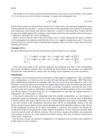
billet or slab is reduced by compressive plastic deformation. When a slab is rolled (Fig.
12.6)
the section is reduced from
t,
to
t2
over a length
1
as it passes through the rolls.
At first sight, it might appear that there would be no sliding (and thus no friction)
between the slab and the rolls, since these move with the slab. But the metal is
elongated in the rolling direction,
so
it speeds up as it passes through the rolls, and
126 Engineering Materials
1
Fig.
12.6.
The
rolling
of
metal
sheet.
some slipping is inevitable. If the rolls are polished and lubricated (as they are for
precision and cold-rolling) the frictional losses are small. We shall ignore them here
(though all detailed treatments of rolling include them) and calculate the
rolling torque
for perfectly lubricated rolls.
From the geometry of Fig. 12.6
l2
+
(r
-
x12
=
r2
or, if
x
=
X(tl
-
t2)
is small (as it almost always is),
7-
1
=
dr(t,
-
t2).
The rolling force
F
must cause the metal to yield over the length
1
and width
w
(normal
to Fig. 12.6). Thus
F
=
a@.
If the reaction on the rolls appears halfway along the length marked
1,
as shown on the
lower roll, the torque is
Fl
T=-
2
giving
(12.16)
Case studies in yield-limited design 127
The torque required to drive the rolls increases with yield strength
uy
so
hot-rolling
(when
cy
is low
-
see Chapter
17)
takes less power than cold-rolling. It obviously
increases with the reduction in section
(t,
-
t2).
And it increases with roll diameter
2r;
this is one of the reasons why small-diameter rolls, often backed by
two
or more rolls
of
larger diameter (simply
to
stop them bending), are used.
Rolling can be analysed in much more detail to include important aspects which we
have ignored: friction, the elastic deformation of the rolls, and the constraint of plane
strain imposed
by
the rolling geometry. But this case study gives an idea of why an
understanding of plasticity, and the yield strength, is important in forming operations,
both for metals and polymers.
Further
reading
C.
R.
Calladine,
Engineering Plasticity,
Pergamon
Press,
1969.
R.
Hill,
The Mathematical Theory of Plasticity,
Oxford University Press,
1950.
W.
A.
Backofen,
Deformation Processing,
Addison-Wesley,
1972.
M.
E
Ashby,
Materials Selection
in
Mechanical Design,
Pergamon Press, Oxford,
1992.
M.
E
Ashby and D. Cebon,
Case Studies
in
Materials Selection,
Granta Design, Cambridge,
1996.
D.
Fast
fracture, toughness
and
fatigue
Chapter
13
Fast fracture and toughness
Introduction
Sometimes, structures which were properly designed to avoid both excessive elastic
deflection and plastic yielding fail in a catastrophic way by
fast fracture.
Common to
these failures
-
of things like welded ships, welded bridges and gas pipelines and
pressure vessels under large internal pressures
-
is the presence of cracks, often the
result of imperfect welding. Fast fracture is caused by the growth
-
at the speed
of
sound in the material
-
of existing cracks that suddenly became unstable. Why do they
do this?
Energy criterion for fast fracture
If
you blow up a balloon, energy is stored in it. There is the energy
of
the compressed
gas in the balloon, and there is the elastic energy stored in the rubber membrane itself.
As
you increase the pressure, the total amount of elastic energy in the system
increases.
If we then introduce a flaw into the system, by poking a pin into the inflated balloon,
the balloon will explode, and all this energy will be released. The membrane fails by
fast fracture,
even though well below its yield strength.
But if we introduce a flaw of the
same dimensions into a system with
less
energy in it, as when we poke our pin into a
partially
inflated balloon, the flaw is stable and fast fracture does not occur. Finally, if we
blow up the punctured balloon progressively, we eventually reach a pressure at which
it suddenly bursts. In other words, we have arrived at
a
critical
balloon
pressure
at
which our pin-sized flaw is just unstable, and fast fracture
just
occurs. Why is this?
To
make the flaw grow, say by
1
mm, we have
to
tear the rubber to create
1
mm of
new crack surface, and this consumes energy: the tear energy of the rubber per unit
area
X
the area of surface torn. If the work done by the gas pressure inside the balloon,
plus the release of elastic energy from the membrane itself, is less than this energy the
tearing simply cannot take place
-
it would infringe the laws of thermodynamics.
We can, of course, increase the energy in the system by blowing the balloon up a bit
more. The crack or flaw will remain stable (i.e. it will not grow) until the system
(balloon plus compressed gas) has stored in it enough energy that, if the crack
advances,
more energy
is
released than is absorbed.
There
is,
then, a
critical pressure
for fast
fracture of a pressure vessel containing a crack or flaw of a given
size.
All sorts of accidents (the sudden collapsing of bridges, sudden explosion of steam
boilers) have occurred
-
and still do
-
due to this effect. In all cases, the critical stress
-
above which enough energy is available to provide the tearing energy needed to
132
Engineering Materials
1
make the crack advance
-
was exceeded, taking the designer completely by surprise.
But how do we calculate this critical stress?
From what we have said already, we can write down an energy balance which must
be met if the crack is to advance, and fast fracture is to occur. Suppose a crack of length
a
in a material of thickness
t
advances by
6a,
then we require that: work done by loads
2
change of elastic energy
+
energy absorbed at the crack tip, i.e.
(13.1)
where
G,
is
the energy absorbed per unit area of
crack
(not
unit area of new surface), and
t6a
is
the crack area.
G,
is a material property
-
it is the energy absorbed in making unit area of crack, and
we call it the
toughness
(or, sometimes, the 'critical strain energy release rate'). Its units
are energy m-' or Jm-'.
A
high toughness means that it is hard to make a crack
propagate (as in copper, for which
G,
=
lo6
Jm-'1. Glass, on the other hand, cracks very
easily;
G,
for glass is only
=
10
J
m-'.
6W
2
6U"
+
G,f6a
Fig.
13.1.
How
to
determine
G,
for
Sellotape adhesive.
This same quantity
G,
measures the strength of adhesives. You can measure it for the
adhesive used on sticky tape (like Sellotape) by hanging a weight on a partly peeled
length while supporting the roll
so
that it can freely rotate (hang it on a pencil) as
shown in Fig.
13.1.
Increase the load to the value
M
that just causes rapid peeling
(=
fast
fracture).
For
this geometry, the quantity
We'
is small compared to the work done by
M
(the tape has comparatively little 'give') and it can be neglected. Then, from
our
energy formula,
6W
=
G,t&
for fast fracture. In our case,
Mg6a
=
G,t6a,
Mg
=
G,t,
Fast
fracture
and
toughness
133
and therefore,
Mg
G,
=
t
Typically,
f
=
2
cm,
M
=
1
kg
and
g
=
10
m
s-~,
giving
G,
=
500
J
m-2.
This is a reasonable value for adhesives, and a value bracketed by the values of
G,
for
many polymers.
Naturally, in most cases, we cannot neglect
6U",
and must derive more general
relationships. Let
us
first consider a cracked plate of material loaded
so
that the
displacements at the boundary of the plate are fixed.
This
is a common mode of loading
a material
-
it occurs frequently in welds between large pieces of steel, for example
-
and is one which allows
us
to calculate
6V1
quite easily.
.I
tF
Fig.
13.2.
Fast fracture
in
a
fixed
plate.
Fast fracture at
fixed
displacements
The plate shown in Fig.
13.2
is clamped under tension
so
that its upper and
lower
ends
are fixed. Since the ends cannot move, the forces acting on them can do no work, and
S
W
=
0.
Accordingly, our energy formula gives, for the onset of fast fracture,
-Sue'
=
G,tGa.
(13.2)
Now,
as the crack grows into the plate, it allows the material of the plate near the crack
to
relax,
so
that it becomes less highly stressed, and
loses
elastic energy.
Sue'
is thus
negative,
so
that
-Sue'
is
positiue,
as it must be since
G,
is defined positive. We can
estimate
6Ue'
in the way shown in Fig.
13.3.
Let us examine a small cube of material of unit volume inside our plate. Due to the
load
F
this cube is subjected to
a
stress
u,
producing a strain
E.
Each unit cube therefore
134
Engineering Materials
1
6a
€
Fig.
13.3.
The release
of
stored
strain energy as a crack grows.
has strain energy
U"
of xu€, or
u2/2E.
If we now introduce a crack of length
a,
we can
consider that the material in the dotted region relaxes (to zero stress)
so
as to lose all
its strain energy. The energy change is
u2
ra2t
Uel
=
-
-
-
2E
2
As the crack spreads by length Sa, we can calculate the appropriate
SU"
as
u2
hat
Sa.
Sa
=
-
d
U"
sue'
=
-
da
2E
2
The critical condition (eqn.
(13.2))
then gives
u2na
2E
-
Gc
at onset of fast fracture.
Actually, our assumption about the way in which the plate material relaxes is
obviously rather crude, and a rigorous mathematical solution of the elastic stresses and
strains around the crack indicates that our estimate of
SU"
is too low by exactly a factor
of
2.
Thus, correctly, we have
u2Ta
E
-
Gc,
which reduces to
7
=
V'EG,
(13.3)
at fast fracture.
Fast fracture at
fixed
loads
Another, obviously very common way of loading a plate of material, or any other
component for that matter, is simply to hang weights on it (fixed loads) (Fig.
13.4).
Here
the situation is a little more complicated than it was in the case of fixed displacements.
Fast fracture and toughness
135
Fig.
13.4.
Fast
fracture
of
a
dead-loaded
plate
As
the crack grows, the plate becomes less
stiff,
and relaxes
so
that the applied forces
move and do work.
6W
is therefore finite and positive. However,
Sue'
is now positive
also (it turns out that some of
6
W
goes into increasing the strain energy of the plate) and
our final result for fast fracture is in fact found to be unchanged.
The fast-fracture condition
Let
us
now return to our condition for the onset of fast fracture, knowing
it
to be
general* for engineering structures
u\Gi
=
m.
The left-hand side of our equation says that
fast fracture will occur when, in
a
material
subjected to
a
stress
u,
a
crack reaches some critical size
a:
or, alternatively, when
material
containing cracks of size
a
is
subjected to some critical stress
u.
The right-hand side of our
result
depends on material properties only;
E
is obviously a material constant, and
G,,
the
energy required to generate unit area of crack, again must depend only on the basic
properties of our material. Thus, the important point about the equation is that
the
critical combination of stress and crack length at which fast fracture commences is
a
material
constant.
crops up
so
frequently in discussing fast fracture that it is usually
abbreviated to a single symbol,
K,
having units MNm-X; it is called, somewhat
unclearly, the
stress intensity factor.
Fast fracture therefore occurs when
The term
K
=
K,
where
K,
(=
m)
is the
critical
stress intensity factor, more usually called the
fracture
toughness.
To summarise:
G,
=
toughness
(sometimes, critical strain energy release rate). Usual units:
kJ
m-*;
*But
see
note
at
end
of
this chapter.
136
Engineering Materials
1
K,
=
\/EG,
=
fvacture
toughness
(sometimes: critical stress intensity factor). Usual
K
=
a&
=
stress intensity factor". Usual units: MNm-x.
units: MN m-x;
Fast fracture occurs when
K
=
K,.
Data
for
G,
and
K,
K,
can be determined experimentally for any material by inserting a crack of known
length
u
into a piece of the material and loading until fast fracture occurs.
G,
can be
derived from the data for
K,
using the relation
K,
=
E.
Figures
13.5
and
13.6
and
Table
13.1
show experimental data for
K,
and
G,
for a wide range of metals, polymers,
ceramics and composites. The values of
K,
and
G,
range considerably, from the least
tough materials, like ice and ceramics, to the toughest, like ductile metals; polymers
have intermediate toughness,
G,,
but low fracture toughness,
K,
(because their
moduli
are low). However, reinforcing polymers to make
composites
produces materials having
good fracture toughnesses. Finally, although most metals are tough at or above room
I
o3
102
10
N
E
(3
1
6'
1
0-2
I
o-~
Ceramics Metals Polvmers ComDosites
Fig.
13.5.
Toughness,
G,
(values at roam temperature unless starred).
*But see note at end
of
this
chapter.
Fast fracture and toughness
Ceramics Metals Polvmers Composites
137
200
100
50
20
4
10
E
35
2
1
0.5
0.2
Fig.
13.6.
Fracture toughness,
K,
(values at room temperature unless starred).
temperature, when many (e.g. b.c.c. metals like steels, or h.c.p. metals) are cooled
sufficiently, they become quite brittle as the data show.
Obviously these figures for toughness and fracture toughness are extremely
important
-
ignorance of such data has led, and can continue to lead, to engineering
disasters of the sort we mentioned at the beginning of this chapter. But just how do
these large variations between various materials arise? Why
is
glass
so
brittle and
annealed copper
so
tough? We shall explain why in Chapter 14.
A
note on the Stress intensity,
K
On pp. 134 and 135 we showed that
K=aJ.rra=JEG,
at onset of fast fracture. Strictly speaking, this result is valid only for a crack through
the centre of
a
wide plate of material. In practice, the problems we encounter seldom
138
Engineering Materials
1
Table
13.1
Toughness,
Gc,
and fracture toughness,
K,
Material
G,
/kJ/mz)
K,
/MN/m%)
Pure
ductile metals (e.9.
Cu,
Ni, Ag, AI)
Rotor steels
(A533;
Discalloy)
Pressure-vessel
steels
(HYl30)
High-strength
steels
(HSS)
Mild steel
Titanium alloys
(Ti6A14V)
GF
RPs
Fibreglass (glassfibre epoxy)
Aluminium alloys (high strength-low strength)
CFRPs
Common woods, crack
I
to grain
Boron-fibre epoxy
Medium-carbon
steel
Polypropylene
Polyethylene (low density)
Polyethylene (high density)
ABS polystyrene
Nylon
Steel-reinforced cement
Cast iron
Polystyrene
Common woods, crack
11
to grain
Pol carbonate
CoLlt/tungsten carbide cermets
PMMA
Epoxy
Granite (Westerly Granite)
Polyester
Silicon nitride,
Si3N4
Beryllium
Silicon carbide
Sic
Magnesia, MgO
CemenVconcrete, unreinforced
Calcite (marble, limestone)
Alumina, A1203
Shale (oilshale)
Soda glass
Electrical porcelain
ice
100-lo00
220-240
1
50
15-118
100
26-1 14
10-100
40-1
00
8-30
5-30
8-20
17
13
8
6-7
6-7
5
2-4
0.2-4
0.2-3
2
0.5-2
0.4-1
0.3-0.5
0.3-0.4
0.1-0.3
0.1
0.1
0.1
0.08
0.05
0.04
0.03
0.02
0.02
0.02
0.01
0.01
0.003
100-350
204-214
50-1 54
55-1 15
20-60
42-60
23-45
32-45
11-13
1
70
1
40
46
51
3
1
2
4
3
10-1 5
6-20
2
0.5-1
1
.O-2.6
14-1 6
0.9-1.4
0.3-0.5
3
0.5
4-5
4
3
3
0.2
0.9
3-5
0.6
0.7-0.8
1
0.2'
'Values at room temperature unless starred.
satisfy this geometry, and a numerical correction to
uvh
is
required to get the strain
energy calculation right. In general we write:
_-
K
=
Y
udna,
where
Y
is the numerical correction factor. Values of
Y
can be found from tables in
standard reference books such as that listed under Further Reading. However,
Fast fracture
and
toughness
139
provided the crack length
a
is small compared to the width
of
the plate
W,
it
is
usually
safe to assume that
Y
=
1.
Further reading
R.
W.
Hertzberg,
Deformation and Fracture Mechanics
of
Engineering Materials,
4th edition,
1996.
B.
R. Lawn and
T.
R.
Wilshaw,
Fracture
of
Brittle Solids,
Cambridge University Press,
197S,
Chap.
J.
E
Knott,
Fundamentals of Fracture Mechanics,
Butterworths,
1973,
Chap. 4.
H.
Tada,
P.
Paris
and
G.
Irwin,
The Stress Analysis of Cracks Handbook,
Del
Research Corporation,
3.
St
Louis,
1973
(for Tabulation
of
Stress Intensities).
Chapter
14
Micromechanisms of fast fracture
In Chapter
13
we showed that, if a material contains a crack, and is sufficiently stressed,
the crack becomes unstable and grows
-
at up to the speed of sound in the material
-
to cause catastrophically rapid fracture, or
fast fracture
at a stress less than the yield
stress. We were able to quantify this phenomenon and obtained a relationship for the
onset of fast fracture
or, in more succinct notation,
K
=
K,
for fast fracture.
It is helpful to compare this with other, similar, 'failure' criteria:
(T
=
uy
for yielding,
M
=
M,
for plastic collapse,
PIA
=
H
for indentation.
(Here
M
is the moment and
M,
the fully-plastic moment of, for instance, a beam;
PIA
is the indentation pressure and
H
the hardness of, for example, armour plating.) The
left-hand side of each of these equations describes the
loading conditions;
the right-hand
side is a
material property.
When the left-hand side (which increases with load) equals
the right-hand side (which is fixed), failure occurs.
Some materials, like glass, have low
G,
and
K,,
and crack easily; ductile metals have
high
G,
and
K,
and are very resistant to fast-fracture; polymers have intermediate
G,,
but can be made tougher by making them into composites; and (finally) many metals,
when cold, become brittle
-
that is,
G,
and
K,
fall with temperature. How can we
explain these important observations?
Mechanisms
of
crack propagation,
1
:
ductile tearing
Let us first of all look at what happens when we load a cracked piece of a
ductile
metal
-
in other words, a metal that can flow readily to give large plastic deformations (like
pure copper; or mild steel at, or above, room temperature). If we load the material
sufficiently, we can get fracture to take place starting from the crack. If you examine the
Micromechanisms
of
fast
fracture
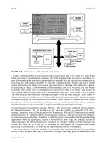
141
Fatigue crack
No.
2
Fast
-fracture
surface
,Fatigue crack
No.
I
Fig.
14.1.
Before it broke,
this
steel
bolt
held
a
seat
onto its mounting at Milan airport. Whenever someone sai
down,
the
lower
part of the cross-section went into tension, causing a crack to grow there
by
metal futigue
(Chapter
15;
crack
No.
1
).
When someone got up again, the upper part went into tension, causing fatigue
crack
No.
2
to
grow. Eventually the bolt failed
by
fast fracture from the larger of the
two
fatigue cracks.
The
victim was able
to
escape with the fractured bolt!
surfaces of the metal after it has fractured (Fig.
14.1)
you see that the fracture surface
is extremely rough, indicating that a great deal of plastic work has taken place. Let
us
explain this observation. Whenever a crack is present in a material, the stress close to
the crack,
ulocal,
is greater than the average stress
u
applied to the piece of material; the
crack has the effect of
concentrating
the stress. Mathematical analysis shows that the
local stress ahead of a
sharp
crack in an elastic material is
(14.1)
The closer one approaches to the tip of the crack, the higher the local stress becomes,
until at some distance
ry
from the tip of the crack the stress reaches the yield stress,
uy,
of the material, and plastic flow occurs (Fig.
14.2).
The distance
ry
is easily calculated
by setting
ulocal
=
uy
in eqn.
(14.1).
Assuming
ry
to be small compared to the crack
length,
a,
the result is
u2a
(14.2)
The crack propagates when
K
is equal to
K,;
the width of the
plastic zone,
ry,
is
then
given by eqn.
(14.2)
with
K
replaced by
K,.
Note that the zone of plasticity shrinks