AIR POLLUTION CONTROL TECHNOLOGY HANDBOOK - CHAPTER 10 doc
Bạn đang xem bản rút gọn của tài liệu. Xem và tải ngay bản đầy đủ của tài liệu tại đây (132.5 KB, 7 trang )
Introduction to Control
of Gaseous Pollutants
Under the auspices of the EPA Center for Environmental Research Information in
conjunction with the EPA Control Technology Center, a handbook for design of
hazardous air pollution control equipment was published in 1986. A revised version
of the handbook was published in June 1991.
1
Current information is furnished through
the Clean Air Technology Center (CATC). This center serves as a resource on all areas
of emerging and existing air pollution prevention and control technologies and their
cost. The information now may be found on the Web at: http//www.usepa.gov/ttn/catc/.
There are six main processes by which a gaseous pollutant may be removed
from an air stream. Table 10.1, taken from the EPA handbook,
1
lists those processes
with the advantages and disadvantages of using each one. The table may be used as
a guide to determine which process may provide the best means of cleaning the air
stream. Separation processes are used as a means of air pollution control for both
particulate matter and gas. These processes essentially remove the pollutant from
the carrier gas resulting in a cleaned gas stream. If the pollutant content of the
cleaned stream meets the effluent emission standards, the cleaned stream can be
discharged to the atmosphere. Absorption and adsorption are both diffusional sepa-
ration processes that can be used to collect hazardous air pollutants. In the case of
absorption, the pollutant is transferred to the solvent which then may need further
treatment. Recovery of the solvent might be undertaken by distillation or by stripping
the absorbed material from the solvent. The problem of treating the waste material
in the stream separated from the solvent remains. If the pollutant material has a
value, adsorption may provide the means for the material to be more readily recov-
ered. In the case of particulate matter, wet scrubbing collects the particles primarily
through the mechanism of inertial impaction. Gaseous contaminants such as sulfur
oxide, nitrogen oxide, or hydrochloric acid, if present along with the particulates,
may be collected simultaneously by absorption.
Many organic materials may be removed by condensation, which is essentially
a diffusional operation. If a suitable coolant is available and the pollutant concen-
tration is high enough, condensation can be very effective in recovering material
that may be used again. For organic pollutants when the concentration is low or
recovering the material is not desired, incineration can be used to convert the
pollutant to carbon dioxide and water. For large emissions such as would be found
in petroleum refineries the pollutant may be flared.
10
9588ch10 frame Page 109 Wednesday, September 5, 2001 9:51 PM
© 2002 by CRC Press LLC
10.1 ABSORPTION AND ADSORPTION
Both absorption and adsorption are diffusional processes employed in the cleanup
of effluent gases before the main carrier gas stream is discharged to the atmosphere.
Both of these operations are controlled by thermodynamic equilibrium. In pollution
control, the concentrations of gases to be treated are relatively low. Thus, the
equipment design is one in which it is reasonable to assume that gas is very dilute.
In absorption it is quite likely that the liquid effluent will be dilute as well. Absorption
of the contaminant from the dilute gas results in a chemical solution of the contam-
inating molecule. However, adsorption is a surface phenomenon in which the mol-
ecules of the contaminant adhere to the surface of the adsorbent.
In diffusional operations where mass is to be transferred from one phase to
another, it is necessary to bring the two phases into contact to permit the change
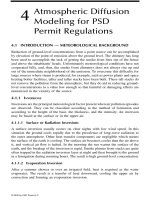
toward equilibrium to take place. The transfer may take place with both streams
flowing in the same direction, in which case the operation is called concurrent or
co-current flow. When the two streams flow in opposite directions, the operation is
termed countercurrent flow, an operation carried out with gas entering at the bottom
and flowing upward, and the liquid entering at the top and flowing down. This
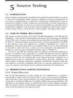
process is illustrated in Figure 10.1. Figure 10.2 shows a combined operation in
which the contaminated gas is first cleaned in a countercurrent operation, and then
the gas is further treated to remove more of the contaminant in a co-current operation.
TABLE 10.1
VOC Control Technologies
Device
Inlet Conc.
PPMV Efficiency Advantages Disadvantages
Absorption 250 90% Especially good for Limited applicability
1000 95% inorganic acid gasses
5000 98%
Adsorption 200 50% Low capital investment Selective applicability
1000 90–95% Good for solvent recovery Moisture and temperature
constraints5000 98%
Condensation 500 50% Good for product or Limited applicability
10,000 95% solvent recovery
Thermal
incineration
20 95% High destruction
efficiency
No organics can be recovered
100 99% Wide applicability Capital intensive
Can recover heat energy
Catalytic
incineration
50 90% High destruction
efficiency
No organics can be recovered
100 >95% Can be less expensive Technical limitations
than thermal incineration that can poison
Flares >98% High destruction
efficiency
No organics can be recovered
Large emissions only
9588ch10 frame Page 110 Wednesday, September 5, 2001 9:51 PM
© 2002 by CRC Press LLC
Countercurrent operation is the most widely used absorption equipment arrange-
ment. As the gas flow increases at constant liquid flow, liquid holdup must increase.
The maximum gas flow is limited by the pressure drop and the liquid holdup which
FIGURE 10.1
Countercurrent flow.
FIGURE 10.2
Combined countercurrent–co-current operation.
9588ch10 frame Page 111 Wednesday, September 5, 2001 9:51 PM
© 2002 by CRC Press LLC
will build up to flooding. Contact time is controlled by the bed depth and the gas
velocity. In countercurrent flow, mass transfer driving force is maximum at the gas
entrance and liquid exit. Co-current operation can be carried out at high gas velocities
because there is no flooding limit. In fact, liquid holdup decreases as velocity
increases. However, the mass transfer driving force is smaller than in countercurrent
operation.
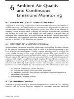
Some processes for both absorption and the removal of particulates employ a
cross-flow spray chamber operation. Here water is sprayed down on a bed of packing
material. The carrier gas, containing pollutant gas or the particulate, flows horizon-
tally through the packing, where the spray and packing cause the absorbed gas or
particles to be forced down to the bottom of the spray chamber where they can be
removed. Figure 10.3 illustrates a cross-flow absorber. The design of cross-flow
absorption equipment is more difficult than vertical towers because the area for mass
transfer is different for the gas and liquid phases.
Continuous and steady-state operation is usually most economical. However,
when smaller quantities of material are processed, it is often more advantageous to
charge the entire batch at once. In fact, in many cases this is the only way the process
can be done. This is called batch operation and is a transient operation from start-
up to shutdown. A batch operation presents a more difficult design problem. Adsorp-
tion is a semi-batch operation in which the contaminant in the carrier gas adheres
FIGURE 10.3
Cross-flow absorber operation.
9588ch10 frame Page 112 Wednesday, September 5, 2001 9:51 PM
© 2002 by CRC Press LLC
to the absorbent until the adsorbent is saturated. The process must then be stopped
to regenerate or replace the adsorbent.
Absorption takes place in either a staged or continuous contactor. However, in
both cases the flow is continuous. In the ideal equilibrium stage model, two phases
are contacted, well mixed, come to equilibrium, and then are separated with no
carryover. Real processes are evaluated by expressing an efficiency as a percent of
the change that would occur in the ideal stages. Any liquid carryover is removed by
mechanical means.
In the continuous absorber, the two immiscible phases are in continuous and
tumultuous contact within a vessel which is usually a tall column. A large surface
is made available by packing the column with ceramic or metal materials. The
packing provides more surface area and a greater degree of turbulence to promote
mass transfer. The penalty for using packing is the increased pressure loss in moving
the fluids through the column, causing an increased demand for energy. In the usual
counter-current flow column, the lighter phase enters the bottom and passes upward.
Transfer of material takes place by molecular and eddy diffusion processes across
the interface between the immiscible phases. Contact may be also co-current or
cross-flow. Columns for the removal of air contaminants are usually designed for
counter-current or cross-flow operation.
10.1.1 F
LUID
M
ECHANICS
T
ERMINOLOGY
Defining velocity through a column packed with porous material is difficult. Even
if a good measure of porosity has been made, it is not possible to assure that the
same porosity will be found the next time a measurement is made after the packing
has been changed. Also, during operation the bed may expand or in the case of a
two-phase, gas-liquid operation, liquid holdup can occur which varies with the flow.
Therefore, determining the unoccupied tower cross-sectional area is difficult, and it
becomes advantageous to base the velocity on the total tower cross-section which
is the usual way to calculate tower flow, especially in absorption design.
The conservation of mass principle at steady state is
(10.1)
where
m = mass flow rate
ρ
= mass density
A = area
V
—
= mean velocity
in compatible units. If G is defined as the mass rate of gas flow, then a superficial
mass velocity can be defined as G where
(10.2)
mAV=ρ
GGA=
9588ch10 frame Page 113 Wednesday, September 5, 2001 9:51 PM
© 2002 by CRC Press LLC
Note that the mean velocity can be calculated from
(10.3)
and that the volumetric flow rate Q is given by
(10.4)
Thus
(10.5)
defines a superficial velocity which is dependent upon the total tower cross-sectional
area.
10.1.2 R
EMOVAL
OF
HAP
AND
VOC
BY
A
BSORPTION
AND
A
DSORPTION
Absorption is widely used as a product-recovery method in the chemical and petro-
leum industry. As an emission control technique, it is more commonly employed
for inorganic vapors. Some common absorption processes for inorganic gases are
• Hydrochloric acid vapor in water
• Mercury vapor in brine and hypochlorite solution
• Hydrogen sulfide vapor in sodium carbonate and water
• Hydrofluoric acid vapor in water
• Chlorine gas in alkali solution
In order for absorption to be a suitable process for emission control, there must
be a suitable solvent which can readily be treated after it leaves the process. Both
vapor–liquid equilibrium data and mass-transfer data must be available or capable
of being estimated. Absorption may be most effective when combined with other
processes such as adsorption, condensation, and incineration.
Adsorption can be used to treat very dilute mixtures of pollutant and air. Acti-
vated carbon is the most widely used adsorbent. Silica gel and alumina are also
frequently used adsorbents. Removal efficiencies can be as high as 99%. The max-
imum inlet concentration should be about 10,000 ppmv with a usual minimum outlet
concentration at 50 ppmv. In some cases it may be advisable to design for minimum
outlet concentration of 10 to 20 ppmv. The maximum concentration entering an
adsorption bed is limited by the carbon capacity and in some cases by bed safety.
Exothermic reactions can occur when some compounds are mixed in an adsorption
bed. Thus, if concentrations are too high, the bed may reach a flammable condition
which could lead to an explosion. It is best to keep the entering concentration to
less than 25% of the Lower Explosive Limit (LEL). For excessively high concen-
trations, condensation or dilution could be used to bring the concentration to a more
reasonable lower level.
VmA=ρ
QAV=
VQA=
9588ch10 frame Page 114 Wednesday, September 5, 2001 9:51 PM
© 2002 by CRC Press LLC
Other limitations for adsorption operation are concerned with the molecular
mass of the adsorbate. High molecular weight compounds are characterized by low
volatility and are strongly adsorbed. Adsorption technology should be limited to
compounds whose boiling points are below 400°F or molecular mass is less than
about 130. Strongly adsorbed high-molecular-mass compounds are difficult to
remove when regenerating the adsorbent. With low molecular mass, compounds
below a molecular mass of 45 are not readily adsorbed due to their high volatility.
On the other hand, lower molecular-weight compounds are more readily removed
during the regeneration process. Furthermore, gases to be treated may have liquid
or solid particles present or have a high humidity. Pretreatment may then be required.
Humidity needs to be reduced below 50% in most cases, or the water will selectively
adsorb to such a great extent that the desired adsorbate to be removed will be blocked
out. Gases to be treated may also be required to be cooled if the temperature is
greater than 120–130°F and the possibility of exothermic reactions exist.
REFERENCE
1.
U.S. EPA Handbook: Control Technologies for Hazardous Air Pollutants,
EPA/625/6-
91/014, Cincinnati, OH, 1991.
9588ch10 frame Page 115 Wednesday, September 5, 2001 9:51 PM
© 2002 by CRC Press LLC