Remote Sensing for Sustainable Forest Management - Chapter 8 pptx
Bạn đang xem bản rút gọn của tài liệu. Xem và tải ngay bản đầy đủ của tài liệu tại đây (184.17 KB, 34 trang )
Forest Change Detection
The principal advantage of Landsat, or any satellite data, is their repetitive nature.
— M. Price, 1986
INFORMATION ON FOREST CHANGE
Change to a forest may be apparent only after long periods of time, a result of many
almost imperceptible and yet powerful forces. Many forests are slow-growing and
relatively long-lived. Forests can give the impression of stasis, climax, an almost
unchanging timeless character. But change is a defining characteristic of forests, in
landscape pattern and function, occurring at virtually all spatial and temporal scales.
An example might be the creation of a soil horizon layer in a conifer forest,
predictable by considering the climate conditions, litterfall, and microbial activity.
Successional changes, growth changes, changes as a result of structural and age
processes, all accrue slowly and with generally small daily, weekly, monthly, even
annual variability. Change can also be rapid and transformative; for example, leaves
can change color and cell structure overnight. Powerful, even cataclysmic, forces
can arrive with little or no warning. Examples might include a wildfire, an insect
outbreak, a windthrow, a harvesting operation, or a prescribed burn.
In managing forests, change frequently follows deliberate human decision mak-
ing and is welcome and predictable — management is often thought of as a way of
regulating changes on the landscape. Change following operations in a local forest
company may be unknown or unavailable at another level (e.g., regional forest
authority or national inventory). Change is sometimes undesirable, often seemingly
random. Detection and monitoring many such forest changes across large areas are
two of the most important tasks that remote sensing can accomplish in support of
sustainable forest management. An important question has emerged that must be
addressed by remote sensing (Coppin and Bauer, 1996): Which changes need to be
detected and how often? There may be requirements to map changes that are not
detectable in the imagery, and there are changes that can be detected, but are not of
interest. There needs to be a balance between changes that are statistically identifiable
by remote sensing and are of significance for forest applications.
Any approach to forest change detection requires a well-prepared data set, and
a specific set of ground observations to calibrate the changes from one type of forest
condition to another. The imagery must be in near-perfect registration, with interband
8
©2001 CRC Press LLC
and intraband noise reduction (Gong et al., 1992) to reduce misidentification of
changes that result from differing image geometry. The imagery should be converted
to a standard quantitative measurement such as reflectance (Saint, 1980), or at least
converted to a normalized data set or index (Lyon et al., 1998) referenced to a single
master observation (Mas, 1999). Among the multitude of possible change detection
approaches, an optimal technique must be selected that can provide the best detection
of changes and the least error (Cohen and Fiorella, 1999). Issues of change accuracy
assessment (Congalton and Brennan, 1998; Biging et al., 1999) must be addressed,
over and above the accuracy assessment considerations in single date image appli-
cations such as classification. For example, in a classification change detection
project, the usual contingency table expands to much greater size (Table 8.1), with
consequences for sampling and field work when possible changes between two image
classifications are considered likely.
Early change detection work focused on the use of aerial photographs in the
interpretation of vegetation change. The need for total coverage in a short period of
time (for example during insect detection surveys) resulted in very high costs
(Beaubien, 1977). Aerial photographic methods can make sense over historical time
periods and in two main types of change detection applications:
TABLE 8.1
Example Change Detection Contingency Matrix for Three Classes at
Two Different Times
Reference Data
a
Class Data
a
F1F2F3F1F2F1F3F2F1F2F3F3F1F3F2
F1 x
F2 x
F3 x
F1F2 x
F1F3 x
F2F1 x
F2F3 x
F3F1 x
F3F2 x
a
Hypothetical three-class example. F1, F2, and F3 represent three different forest types; the
class confusion matrix must consider the possible misclassification of pixels in two dates.
Source: Modified from Congalton and Brennan (1998).
©2001 CRC Press LLC
1. Detailed vegetation assessments of change at large spatial scales (i.e., fine
resolution but small extent or area coverage), or
2. Broad landcover assessments of change at small spatial scales (i.e., coarse
resolution [less detail] over a large spatial extent; large area coverage with
Level I or II changes).
In the first instance, over small areas, “studies based on aerial photography may
be used for very detailed assessment of rates and patterns of change, and to test
hypotheses regarding these factors” (Price, 1986: p. 486). As always in interpreting
aerial photographs, there is the difficulty related to the boundaries of vegetation
types (Abeyta and Franklin, 1998) which when “recognized from the interpretation
of photographs will not always coincide with those derived from ground-level studies
using classical methods for the description of vegetation; depending on film type,
filtering, image scale, time of acquisition and mode of analysis” (Price, 1986: p.
486). The homogeneity assumption can create difficulties that cascade throughout
the use of the data. Usually, though, the original photos are stored and can be accessed
easily, and are readily interpreted without specialized training or equipment.
The ease of acquisition and interpretation of photography guarantees that, in many
change detection applications, this type of data is an appropriate choice (Pitt et al.,
1997). In fact, at the operational level most change detection is probably conducted
by people looking at the newest photography and comparing it to the GIS database,
or even their personal knowledge of the management unit. Aerial photography is
under continual improvement (Caylor, 2000), and in its many forms (e.g., film size
can be metric, supplemental, oblique, and high-altitude, and film emulsions can be
natural color, color infrared, reversal (or positive), and panchromatic) continues to
be an indispensible management tool in change applications (Lowell et al., 1996).
At large spatial extents, coarse changes in landcover or vegetation type can be
considered using aerial photographs. Principally, historic vegetation patterns would
be of interest. The difficulties in using uncontrolled photomosaics and variable
radiometry aerial photographs over large areas are reasonably well known and
relatively easily accommodated by experienced air photointerpreters. For example,
Burns (1985) used aerial photographs covering three large test areas in Lousiana,
Kansas, and Arizona, and compared the results of change detection to those obtained
from Landsat imagery. Only Level I landcover changes (from forest to agriculture,
agriculture to urban, range to agriculture, and range to urban) could be reliably
detected by Landsat and confirmed by aerial photographic work over a five-year
period. Accuracies were estimated to exceed 75% in all categories for large areas.
Aerial photographic techniques will certainly be required when considering
landscape changes in the era before routine satellite observations were collected.
For example, Turner (1990) used the manual interpretation of air photos dating from
the 1930s through the 1980s to monitor changes in eight Level I and II landcover
categories in Georgia (urban, agricultural, transitional, improved pasture, coniferous
forest, upper deciduous forest, lower deciduous forest, and water). The forest classes
were defined by a canopy cover of at least 50%, and an estimated average tree height
of 3 m. Photographs at three sites using three aerial photographic scales (1:20,000,
1:40,000, and 1:60,000) were examined over a 50-year interval. Each photo pair
©2001 CRC Press LLC
was viewed under a mirror stereoscope and the interpreted land cover polygons
transferred to an acetate overlay. A grid with cells representing 1 ha was then placed
over the acetate, and the land cover representing the greatest proportion of each cell
was digitized to create a raster database. Differences at each time period could be
summarized by area and location, and the raster database subjected to landscape
pattern analysis.
Digital methods of change detection were largely developed for, and applied to,
satellite imagery to take advantage of the new repetitive, synoptic digital data (Saint,
1980; Howarth and Wickware, 1981). At first, such methods were not widely used
— possibly because of the relatively coarse spatial resolution of the early satellite
data obtained by the Landsat MSS sensor — but more likely, as in other remote
sensing applications, users experienced difficulty in interpreting the data (Wickware
and Howarth, 1981; Singh, 1989; Coppin and Bauer, 1996). As new satellite and
airborne images became available, it appears more likely that remote sensing data
acquired repetitively at short intervals and with consistent image quality will be a
necessary database for forest change detection (Mas, 1999).
The simplicity of the basic idea of digital remote sensing change detection is
deceptive (Donoghue, 1999): consider a pixel or group of pixels over time and
determine the likelihood of change. The basic changes in spectral response caused
by forest harvesting, silviculture, and natural disturbance are similar; typically,
following the removal or significant decrease of forest canopy cover there is an
increase in visible reflectance and a decrease in near-infrared reflectance. The greater
the amount of forest removed, the greater the changes in reflectance that are observed.
Similar patterns have been observed in SAR imagery; cleared areas are brighter in
SAR spectral response than are forested surfaces.
Several early problems in digital change detection have been overcome with
time and experience. For example, it was felt that small changes of local interest
could not be detected reliably by satellite remote sensing (the spatial resolution
problem). This issue has largely disappeared as the types of changes that can be
detected have become better understood and the data options have increased. Expe-
rience has enabled greater confidence in the application; in Brazil, for example,
separating acacia and eucalyptus plantations from natural forest was more readily
accomplished with TM compared to MSS data because of the improved spectral,
spatial, and radiometric resolutions (Deppe, 1998). Another reason was that the field
data were collected at a time closer to the acquisition date of the TM data — this
will often be the case. In any event, in digital change detection it has often been
found that the TM data are actually too fine and need to be generalized to reduce
the tremendous data volume to a more manageable level. Principal components
analysis is often the data reduction tool of choice (Fung and LeDrew, 1987).
Recently, the use of satellite imagery in change detection applications has flour-
ished; change detection is one of the most powerful reasons for using digital remote
sensing data, and certainly satellite remote sensing imagery (Lunetta and Elvidge,
1999). Continual refinement of the methods of change detection by satellite and
airborne remote sensing has been provided by numerous reported examples of forest
changes caused by natural disturbances, such as floods (Michener and Houhoulis,
1997), winds (Ramsay et al., 1998; Mukai and Hasegawa, 2000), wildfires (Koutsias
©2001 CRC Press LLC
and Karteris, 2000; Salvador et al., 2000), insects and disease (Leckie et al., 1992;
Franklin and Raske, 1994), and other forest decline phenomena (Yuan et al., 1991;
Brockhaus et al., 1993).
The digital methods force more precise answers to questions of methodology in
change detection than those required by manual aerial photointerpretation of land-
cover or vegetation types:
• What is a significant change?
• How does one assess the accuracy of change detection?
The first question is typically addressed by establishing thresholds of change. The
method of establishing thresholds depends on the image analysis technique, but
likely involves a type of training data collected in known change locations (Malila,
1980; Fung and LeDrew, 1988; Cohen et al., 1998). Identifying the specific nature
of change in those areas detected with a high probability of change would no doubt
require field or air photo work. Often, the only way to check on the early image
data is through interpretation of historical air photographs (Hansen et al., 2000).
Assessing the accuracy of change detection typically involves images that were
acquired in the past, often under less than ideal conditions. Sampling for accuracy
assessment in this situation is problematic. In addition, a wide variety of possible
sources of error in assessing accuracy in a change detection project originate in the
classification scheme, registration problems, and change detection algorithms (Big-
ing et al., 1999).
Which algorithm will be able to detect change reliably but not misfire? While
the techniques are variable, two broad approaches are common, based on Johnson
and Kasischke (1998):
1. Data transformation (e.g., image differencing, PCA), and
2. Change labeling (e.g., regression, classification).
The classification approach is generally indicated when the differences between the
two images to be compared are large (e.g., very different ground conditions, different
seasons, or different sensors). The idea is to provide a classification of each date
separately, and then compare the results (Jakubauskas et al., 1990; Franklin and
Wilson, 1991b; Mas, 1999). Comparative studies have shown that if the change is
large and distinct (e.g., clearcuts, fires, or urban development), then classification
techniques can be highly effective. The classification approach can also reduce the
influence of other factors, such as differing radiometric properties, by independently
placing the spectral responses in the appropriate classes before comparing informa-
tion from different dates (Pilon et al., 1988; Mas, 1999). A disadvantage of this
approach is that, even though many changes that are smaller than individual pixels
can occur, only a complete change in class membership will be detected (Foody and
Boyd, 1999). Despite having no standardized change detection protocol, digital
methods of change detection and identification are increasingly considered for use
with all types of airborne imagery, including digitized aerial photography (Price,
1986; Meyer et al., 1996) and SAR data (Cihlar et al., 1992).
©2001 CRC Press LLC
Image differencing has been accomplished using many different algorithms,
ranging from simple subtraction to complex statistical manipulations such as
expressed in a principal components analysis (Fung and LeDrew, 1987). Compari-
sons of different image differencing, and classification procedures has been the focus
of several recent studies aimed at developing an optimal change detection technique
(Muchoney and Haack, 1994; Collins and Woodcock, 1996; Mas, 1999; Morisette
et al., 1999). Image differencing using the original bands, or a transformation of the
original bands, requires greater attention to radiometric issues and may also present
information that is more difficult to interpret. Rather than a simple class-by-class
summary, image differences must be related to the changing feature on the ground;
changes in reflectance, for example. More complex change detection procedures are
typically an elaboration of the concept of image differencing and may be still more
difficult to interpret. Change vector analysis, for example, provides a magnitude of
change and a directional vector for detected changes in imagery, but these outputs
appear to be inadequately described in the literature. Their use may be subject to
uncertainties not yet fully understood (Cohen and Fiorella, 1999).
Generally, differences are small in the performance of the change detection
algorithms tested to date. Most are readily available in commercial image processing
systems. A more important factor may be the different types of data that are available.
There may be a difficulty in detecting change on recent satellite imagery compared
to coarser resolution historical data; this coarser resolution data may be in the form
of a satellite image (e.g., Landsat MSS data) or a polygonal database generated by
aerial photography and field surveys. The polygonal data represent a special form
of the change detection problem; rarely will it be possible to compare polygon to
polygon. Even in the traditional task of forest inventory change, it is more typical
that the inventory is completely replaced rather than updated in a change detection
procedure (Lowell et al., 1996).
Instead, tools such as the Polygon Update Program (PUP) (Wulder, 1998a) have
been devised to examine pixels within polygonal structures such as forest stands.
Not only can the forest inventory guide the change detection analysis to the areas
of highest interest, but the polygons themselves can provide a way of organizing
the landscape such that the changes are reported as aggregated within polygons.
This process has been termed polygon decomposition (Wulder, 1998a) and refers to
the process of analyzing previously delineated polygon areas using ancillary digital
information acquired from an independent source. Often, the mix of vegetation is
of interest within the polygonal structures or forest stands (Carpenter et al., 1999).
The idea is to use those independent data typically acquired through remote sensing
to provide insight into the internal characteristics of the polygonal area, typically
delineated using aerial photointerpretation. The polygon, or vector, data are used as
the context for the analysis of remote sensing, or raster, data. The polygonal data
represent areas of generalization, but the remotely sensed data can be used to make
measurements or aggregate information in a meaningful way within those general-
ized areas.
In essence, the polygonal information is a way of structuring or stratifying the
remote sensing information for analysis (Varjö, 1996); another way to view this
process is to consider that the remote sensing data are a way of explaining the
©2001 CRC Press LLC
polygonal structure. The fusion of the raster and vector data allows for the augmen-
tation of current information in the previously delineated polygon areas. The current
information available from the remotely sensed data may be physical properties such
as spectral response values (Chalifoux et al., 1998), or categorical properties such
as the result of an image classification or change detection procedure.
HARVESTING AND SILVICULTURE ACTIVITY
C
LEARCUT AREAS
Forest harvesting by clearcutting has long been monitored by satellite remote sens-
ing, with accuracies suitable for operational mapping in many different types of
forests and with a variety of sensors. Since forest clearings are generally visible in
hardcopy aerial and satellite imagery, both analogue or manual interpretation and
digital approaches have been used to:
1.Detect forest clearcuts (Drieman, 1994; Banner and Ahern, 1995; Pilon
and Wiart, 1990; Yatabe and Leckie, 1995; Murtha and Pollock, 1996);
2.Map clearcut boundaries (Rencz, 1985; Hall et al., 1989a; Hall et al.,
1991c; Hall et al., 2000b);
3.Direct field sampling to areas of high likelihood of change (Kux et al.,
1995; Varjö, 1996);
4.Provide information on successful legal enforcement of protected areas
(Fransson et al., 1999);
5.Provide landscape-level summaries of area changes (Hansen et al., 2000).
The principal reason to consider satellite imagery in the task of clearcut mapping
is the reduced cost compared to aerial photographic surveys and field mapping of
cutblocks. Before cost savings can be realized, it is necessary to show that the same
levels of accuracy that are obtainable using traditional methods are possible with
satellite remote sensing techniques. For example, in Alberta, the two major physical
criteria for accepting an alternative image source for cutover update were (1) cutover
area accuracy and (2) boundary placement accuracy. Using standard manual photo-
morphic techniques, Hall et al. (1989a) showed that overall cutover area accuracies
were 86.7, 89.5, and 86.9% on medium-scale airphotos, Landsat TM, and MSS
imagery, respectively. Overall, cutover boundary placement errors for air photo
techniques, Landsat TM, and MSS imagery were 30.1, 24.9, and 38.3 m, respectively
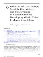
(Figure 8.1).
In a cost analysis, Landsat TM images offered a 12:1 cost savings in data
acquisition over aerial photography (Hall et al., 1989a). The MSS imagery were not
recommended for operational mapping of clearcuts, but the TM data were considered
an appropriate alternative to the use of air photos, at least in the type of forest studied
(predominately conifer stands). This study was recently updated using IRS 5.8 m
panchromatic satellite data with a similar conclusion; under certain circumstances
satellite remote sensing imagery can provide cutblock updates comparable to those
acquired with aerial photographic methods (Hall et al., 2000b). Errors were even
©2001 CRC Press LLC
FIGURE 8.1 A simple linear regression of actual cutover area vs. two types of image
interpretations based on Landsat MSS and TM data. Using enlarged color composites, TM-
predicted cutover area was within guidelines suggested for area and boundary placement of
cutovers in Alberta. (From Hall, R. J., A. R. Kruger, J. Scheffer, et al. 1989. For. Chron., 65:
441–449. With permission.)
0
20 40 60 80 100 140
20
0
40
60
80
100
120
140
Actual Cutover Area
0
20 40 60 80 100 140
20
0
40
60
80
100
120
140
Actual Cutover Area
0
AFS Cutover Area
20 40 60 80
20
0
40
60
80
100
120
140
Actual Cutover Area
120
120
0
20 40 60 80 100
20
0
40
60
80
100
120
140
Actual Cutover Area
0
20 40 60 80 140
20
0
40
60
80
100
120
140
Actual Cutover Area
120
Actual = 1.06655 x TM
Actual = 1.05619 x AFS
Actual = 1.07930 x MSS
Landsat MSS Cutover Area
Landsat TM Cutover Area
©2001 CRC Press LLC
lower than with the TM imagery; boundary placements ranged from 16 to 20 m of
1:20,000-scale photogrammetric measurements. However, visual interpretation is a
time-consuming and labor-intensive method for large-area mapping (Sader, 1995).
Using six Landsat satellite images of a 1.2-million-hectare area in the central
Oregon Cascade Range, Cohen et al. (1998) mapped cutovers between 1972 and
1993. All images were resampled to 25 m, masked using a DEM to eliminate lower
elevation agricultural areas, transformed to Tasseled Cap vegetation indices, sub-
tracted from previous images to create image differences, and classified using an
unsupervised clustering algorithm. Comparison of the resulting harvest map with
an independent reference database (using three different methods) indicated that an
overall accuracy of greater than 90% was achieved. This is an important study not
only for the demonstration of mapping cutovers with high accuracy from satellite
data; the area covered in the application was so large, and covered such a long time
period, that to attempt this mapping in any other way is almost inconceivable.
In Canada, several studies have been reported that confirm the utility and accu-
racy of clearcut mapping from digital satellite data. Using Landsat TM band 5
difference images in Nova Scotia, cutover area estimates differed by a maximum of
10% when compared to traditional aerial photograph mapping (Rencz, 1985); this
difference was almost entirely attributed to other environmental changes such as
gravel pits, flooded areas, and blowdown, and to the prevalence of small cutovers
less than 1.5 ha in size in mixedwood stands. Using SPOT panchromatic images
and simulated Radarsat imagery, clearcuts were mapped in Alberta (Banner and
Ahern, 1995); very high levels of agreement were obtained, with errors decreasing
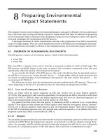
with greater spatial resolution and when using nadir imagery (Figure 8.2).
Using multiseason airborne C-band SAR imagery for clearcut detection in New-
foundland, total clearcut areal error was less than 4% when compared to a control
sample of clearcuts mapped using 1:12,500-scale color aerial photographs (Drieman,
1994). With SAR data, image interpretation concerns exist because of the strong
dependence on topography and the typically low inclination angles (Edwards and
Rioux, 1995). Great care must be employed in selecting image dates for comparison
because of the large range of backscatter response that can be obtained from vege-
tation targets seasonally (Cihlar et al., 1992). Single date, single polarization, single
incidence angle SAR data are typically presented as black and white gray-scale
imagery, which can be difficult to interpret because of their highly textured and
speckled appearance.
In tropical areas, the opportunities for field observations and the ancillary data
(e.g., air photos and topographic maps) necessary for investigating forest changes
may be lacking, making satellite imagery and digital methods an ideal information
approach (Sader, 1995). Lowry et al. (1986: p. 904) suggested that “the accurate
and ready delineation of cleared areas and plantations indicates that SAR is a reliable
remote sensor for estimating and monitoring tropical deforestation and to some
extent reforestation.” In comparing airborne and simulated satellite C-band SAR
data and Landsat TM data, a very high level of agreement was obtained in providing
annual estimates of large (1000 to 10,000 ha) and medium (100 to 1000 ha) clearings
in Brazil (Kux et al., 1995).
©2001 CRC Press LLC
FIGURE 8.2 Strong relationships were found in a comparison of cutover areas measured
manually using SPOT panchromatic imagery and three types of simulated Radarsat data in
Alberta. Areas with steeper topography, variable forest types, and more variable cutting
practices would likely be more difficult to interpret. (From Banner, A. V., and F. J. Ahern.
1995. Can. J. Rem. Sensing, 21: 124–137. With permission.)
0
0
Areas using Nadir Mode SAR Imagery (ha)
20 40 60 80
10
20
30
40
50
60
70
80
Areas using SPOT Imagery (ha)
0
0
Areas using Fine Mode Simulation (ha)
20 40 60 100
10
20
30
40
50
60
70
80
Areas using SPOT Imagery (ha)
80
0
0
Areas using Standard Mode Simulation (ha)
20 40 60 80
10
20
30
40
50
60
70
80
Areas using SPOT Imagery (ha)
y= 0.96 X + 0.74
r = 0.93
2
y = 0.92 x + 0.01
r = 0.75
2
y= 0.90 X + 1.40
r = 0.87
2
©2001 CRC Press LLC
Deforestation in Rhondonia due to human occupation was estimated to have
reached at least 52 million hectares by 1996 (INPE, 1998). In order to better
understand the deforestation process and assess some of the effects of the long-term
occupation, 1977, 1985, and 1995 Landsat imagery were classified separately and
compared (Alves et al., 1999). Deforested areas included pastures, annual and
perennial crops, burned areas, and secondary vegetation. More than 90% of the total
deforestation in the 1985 Landsat image, and 81% of the total deforestation in the
1995 Landsat image, occurred within 12.5 km of the areas deforested in 1977. High
rates of forest depletion were linked to new settlements and roads into previously
remote areas.
More automated methods of change detection have been developed and prelim-
inary results are encouraging for their use in boreal forests. In Finland, a method
was developed to analyze changes that deviate from normal vegetative succession.
Such changes are usually rather rapid and of small areal extent when compared to
the area changes related to natural vegetative succession (Häme et al., 1998). A
typical example of such a change is a clearcut, but even damage caused by insects
can be profound over a short period of time when compared to a successional change.
The system used two images acquired on different dates as input:
• To reduce the mixed pixel effect, find homogeneous areas that can be used
as seeds for clustering image data;
• Based on these training data, apply a clustering procedure separately to
each image, and then list and name the cluster pairs by referring to a
common index (in this case the NDVI);
• Transfer the clusters from the first image to the second image in the series,
and note statistical differences in clusters in this second image (e.g., a
high standard deviation);
• In those clusters with statistical differences between the first and second
image, scale the differences and note the direction of the change in the
vector;
• Indicate using output channels (such as the NDVI) the direction (positive
or negative value) and magnitude of change.
The method was tested in southern Finland and was found to reliably detect and
identify clearcuts (Häme et al., 1998). In addition, the method provided information
on forest damage even though the actual magnitude of the change was small com-
pared to the magnitude of change in clearcut areas.
An extensive system of change detection was implemented by Varjö (1996) in
Finland; the aim was to find a method that could be used to check existing updates
done by field or aerial photointerpretation, and subsequently, to direct field efforts
to areas where the updates were not in accord with the remote sensing method.
Clearcut areas and thinned and holdover removal stands were separated using mul-
titemporal Landsat TM data after radiometric and geometric corrections were
applied. The classifier worked within stands delineated the traditional way (by aerial
photointerpretation); the mean and variance of reflectance was considered in each
©2001 CRC Press LLC
stand in each of the two images. When comparing the image classification results
to recorded treatments, almost 7% of the stands were recommended for field inspec-
tion because of discrepencies between the observations by satellite and the existing
records over the two-year period of the study. The suggestion was made that for a
10-year inventory cycle, fewer than one third of the stands now visited on the ground
would need to be surveyed.
A variation of this approach has been used in the Hinton, Alberta region to map
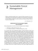
clearcuts over a two-year period with Landsat TM data. Figure 8.3 shows the binary
image (clearcuts shown in black) that existed in 1996, and the additional harvesting
that took place in 1997 and 1998. The accumulation of clearcutting is shown as an
input to the application of landscape metrics to determine the spatial structure of
the area, discussed later in this chapter.
PARTIAL HARVESTINGAND SILVICULTURE
Compared to clearcut and harvest block detection by remote sensing, fewer studies
have examined the effect of silvicultural activities or partial harvesting on the spectral
response of forests (Gerard and North, 1997). Typically, the disturbance to the forest
canopy resulting from these activities is much less than that which occurs during
clearcutting (Chapter 8, Color Figure 1*). Subsequently, it is more difficult to use
satellite spectral response, particularly in their detection. In manual interpretation
of satellite imagery, partial harvesting in mixedwood stands known to occur in one
Alberta study area was not consistently mapped (Hall et al., 1989a). The tonal
differences were simply too small to be noticed by the image analysts when mapping
at 1:100,000 scales or smaller.
In Scandinavia, most forests stands are subject to between one and three thin-
nings before the final clearcutting (Olsson, 1994). Normally, between 20 and 50%
of the basal area is removed in one thinning; commercial logs are usually removed
but the cutting waste remains. The material left on the ground, and the gaps created,
present a possible spectral response that can be detected if the spectral, spatial, and
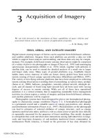
radiometric resolutions of the sensors are adequate (Figure 8.4). After thinning,
Landsat TM image reflectance increased in all bands except the near-infrared (band
4). Because the visible bands were sensitive to the amount of canopy that was sunlit
and the amount of shading of the ground that occurred with a dense forest cover,
“it can be assumed that the change in shadow patterns is an important factor behind
the reflectance increase” (Olsson, 1994: p. 229). In the near-infrared portion of the
spectrum, a small decrease in reflectance could be generally attributed to a reduction
in the proportion of photosynthetically active canopy, the covering of the ground
with cutting debris, and the changes in tree species proportions. In the middle infrared
portion of the spectrum (e.g., TM bands 5 and 7), there was less diffuse scattering
of light. Measurements in these areas can be as sensitive to shadow patterns as the
visible bands (Horler and Ahern, 1986; Chen et al., 1999a).
A similar partial harvesting/silvicultural situation exists in New Brunswick. In
one recent study, 424 balsam fir stands were found with changes detected by a
* Color figures follow page 176.
©2001 CRC Press LLC
FIGURE 8.3 A Landsat TM image classification to reveal clearcuts in a boreal forest environment suggests the power of the change detection approach
for this forestry application. In 1996 the clearcuts (shown as black patches), many of which were more than 10 years old, could be accurately delineated
and separated from the surrounding forest mosaic (white background). By overlaying a 1998 Landsat TM image, new clearcut areas could be readily
distinguished from the older cuts and the mature or young forests of the area. (Example provided by L. M. Moskal, University of Kansas.)
0
10 km
1996 Time Period 1998 Time Period
Clearcuts
©2001 CRC Press LLC
1992–1997 Landsat Thematic Mapper remote sensing classification procedure (Fran-
klin et al., 2000b). First, the image data were corrected for atmospheric effects, then
transformed to brightness/greenness/wetness indices. The resulting six indices (three
from each of the two image dates) were selected for classification using a maximum
likelihood classifier. Areas that had been cutover in the intervening years were
distinct in that they showed increased brightness, decreased greenness, and decreased
wetness. In these stands, some 76,882 pixels were found to have changed in roughly
equal proportions in three classes of change: light, moderate, and severe. Light
changes were attributed to partial harvesting and precommercial thinning, and mod-
erate changes were attributed to clearcutting with legacy patches and some hardwood
selection cutting. Severe changes were clearcuts. The classification accuracy was
estimated to be approximately 70%.
The effect of these physical changes to forests has been difficult to predict;
typically, reflectance in all bands would increase with a reduction in basal area.
However, in some areas a reduction in basal area has been followed closely by an
increase in leaf area as the understory responds to the opening of the canopy (Franklin
et al., 2000b) (Chapter 8, Color Figure 2). This increase in leaf area can decrease
reflectance in visible bands and increase near-infrared reflectance; the opposite effect
to that observed by Olsson (1994) in areas with little or no vegetative understory.
In areas of spruce budworm mortality, stands with a significant deciduous component
FIGURE 8.4Annual reflectance change after cutting as a function of thinning as observed
by the Landsat TM sensor in a boreal forest environment. Thinned areas had a much smaller
difference in annual spectral response compared to seed tree areas which, in turn, had a
smaller difference than was observed in clearcut areas. (From Olsson, H. 1994. Rem. Sensing
Environ, 50: 221–230. With permission.)
00
∆R
Thinning Grade (%)
0.02
0.04
0.06
0.08
0.1
0.14
0.12
0
0
-0.02
20
40 60 80 100
TM 5
TM 7
TM 3
TM 4
TM 2
TM 1
Clearfelled areas
Seed tree stands
Thinning cuttings
0.16
©2001 CRC Press LLC
showed a negative relationship between conifer volume and near-infrared reflectance
(Ahern et al., 1991). That is, stands with lower spruce-fir volumes — caused by tree
mortality rather than thinning or harvesting — had increased near-infrared reflec-
tance because of the exuberant understory growth (Figure 8.5).
REGENERATION
Regeneration surveys by aerial and field methods are a standard practice in many
forest jurisdictions. What is needed is an assessment of stocking levels and planting
success. This information can be obtained by plot-based or strip cruising, often coupled
with air photography. Remote sensing — through supplemental aerial photography
FIGURE 8.5A higher near-infrared reflectance in spruce-fir stands thinned by spruce bud-
worm tree mortality in New Brunswick. As the crown was opened up, near-infrared reflectance
increased as a result of the exuberant understory beneath the conifer canopy. Total LAI
increased despite the reduction in canopy LAI. In another area, the opposite effect may be
observed; a reduction in canopy leaf area could cause a reduction in near-infrared reflectance
viewed from above the canopy. (From Ahern, F. J., T. Erdle, D. A. MacLean, et al. 1991. Int.
J. Rem. Sensing, 12: 367–400. With permission.)
0.18
0
300
200
250
150
100
50
0.20 0.22 0.24 0.26 0.30 0.320.28
y = -1488 R4 + 499
r = 0.808
2
R4 = TM Band 4 Reflectance (near-infrared)
Live Spruce Fir Volume (m ha )
3-1
©2001 CRC Press LLC
(Zsilinszki, 1970; Hall and Aldred, 1992) — has long played a significant role in such
regeneration surveys through direct estimation of cover, seedling, and stem counts.
Satellite remote sensing methods of forest regeneration assessment are much
less common (Fiorella and Ripple, 1993b; Lawrence and Ripple, 1999). One
approach is to consider the reflectance characteristics of the development of forest
stands over time, from establishment or initiation (usually by disturbance) through
the thinning phase, into stand maturity, and the various end points for forest eco-
systems. Initially, as the new plants begin to grow the regenerating area would appear
bright in all bands, gradually decreasing as decreasing amounts of the soil surface
and understory were visible to the sensor. Increased absorption by greater concen-
trations of pigments in the canopy leaves, and increased shadowing, may reduce
reflectance still further. Along these lines, Peterson and Nilson (1993) and Nilson
and Peterson (1994) introduced the concept of the stand reflectance trajectory as
discussed in Chapter 7. By this, it was meant that each of the stages in the devel-
opment of the stand — for example, the successional stages — could be considered
predictable in terms of reflectance.
In Tanzania, Prins and Kikula (1996) reported that detection of strong coppicing
from roots and stumps in miomba woodland (Brachystegia and Julbernadia) was
possible using Landsat MSS data acquired in the dry season after the first year of
fallow. In northern California, 30 Landsat images acquired over almost 30 years were
used to track the reflectance changes in clearcuts and regenerating areas (Kiedman,
1999). Images were calibrated and normalized so that differences in reflectance could
be observed and quantified over time. A spectral mixture analysis approach was used;
each pixel was modeled to determine the vegetation, soil, and shade fraction based
on an extensive endmember library. As a single stand was observed by plotting the
reflectance measurements over time, the endmember fractions changed in a predictable
way according to the physical changes in the proportion of vegetation, soil, and shade
induced by the clearing, regeneration, and maturing of the vegetation in the stand.
The year a stand was cut was obvious by the significant reduction in the vegetation
fraction; as the stand regenerated, the vegetation fraction gradually increased and the
soil fraction gradually decreased. Eventually, as the forest canopy closed and the stand
reached maturity, the vegetation fraction decreased and the shade fraction increased.
These studies provide good examples of the type of data and forest models that
remote sensing can provide forest managers for regeneration assessment. First,
depending on vegetation phenology and image characteristics, it should be possible
to detect regeneration soon after disturbance has occurred. Then, based on observa-
tion of spectral response over time, and the calibration of those patterns with field
data, a monitoring tool can be designed that is relatively inexpensive, covers large
areas, and is quantitative.
NATURAL DISTURBANCES
F
OREST DAMAGE AND DEFOLIATION
Forest impact is defined as the “net effect of an organism, after all beneficial and
detrimental influences have been balanced, on the quantity and quality of the multiple
©2001 CRC Press LLC
resources expected from the land” (Alfaro, 1988: p. 281). Forest damage is a negative
impact, and is generally considered to have occurred when there is (1) a reduction
in growth or (2) actual mortality of trees. Forest damage can arise from a wide range
of environmental and artificial causes originating from biological, hydrological, and
atmospheric sources. Damage may be caused by forest insects, various diseases,
fungi, mechanical or physical forces (such as machines, flooding, and winds) (Ram-
sey et al., 1998; Mukai and Hasegawa, 2000). Damage may be caused by forest
decline phenomena linked to air pollution (Tømmervik et al., 1998), climatic stress,
or changing stand dynamics.
The concept of forest damage is intrinsically related to the general concept of
forest ecosystem health — one of the principal indicators underlying a sustainable
forest management strategy. Core indicators of health usually include plant and site
characteristics; dendrology, mensuration, crown assessments (density, transparency,
diameter, ratio, and dieback); crown and bole damage; altered wood quality; soil
chemistry; root disease; and presence, condition, or absence of bioindicator plants.
Remote sensing inputs to these broad areas have been relatively few (Riley, 1989);
forest health monitoring will continue to be principally a field-based activity — “it
is only through careful field observations that any statements will be possible about
the status of individual tree species and forest ecosystems today and in the future”
(Innes, 1992: p. 52). Repeated measurement of crown density, discoloration and
dieback, needle retention, premature leaf loss, and shoot death are known to be
subjective. Such measurements are demonstrably useful in forest management, as
careful training showed that between-stand variability was greater than it was in
assessment of plantations — in other words, even-aged and predominantly single-
species stands (Innes and Boswell, 1990). Most forest health assessments occur in
conditions that are much less ideal.
Others have stressed the unecessary subjectivity and high cost of such detailed
field observations, coupled with a strong desire to make indicator measurements not
currently feasible; for example, “to generate forest damage maps in real time,
providing a versatile and powerful tool for forest managers” (Reid, 1987: p. 429).
There is a clear need for continued development of forest health monitoring by
remote sensing. Two approaches appear viable (Dendron Resources Inc., 1997):
1. Detecting indicators or markers of physiological response to stress
(derived from leaf reflectance, canopy chemistry, and bioindicator
plants), and
2. Capturing long-term changes in health and vigor by classifying and mea-
suring characteristics of stand development.
Managers need to know where, when, and why certain biotic agents cause
changes in structure, composition, growth, and development of the forest (Stoszek,
1988). While no single inventory and monitoring method is likely to be found for
all types of forest damage and aspects of forest ecosystem health, there would appear
to be a clear role for remote sensing based on remote (spectral response) detection
of differences in color (Murtha, 1976; Rock et al., 1986) and detection of a loss of
plant chlorophyll, turgidity, foliage, or other growing organs (Hoque et al., 1992).
©2001 CRC Press LLC
The approach is to try and relate differences in remotely sensed spectral response
to chlorosis (yellowing), dehydration, foliage reddening, or foliage reduction over
time; the idea is that these differences can be classified, correlated, interpreted, or
otherwise related to known damage or stress conditions such as defoliation caused
by insect activity (Hall et al., 1983) or differences in internal leaf structure caused
by ozone and pollutants (Essery and Morse, 1992). This approach has led to suc-
cessful use of remote sensing in at least three forest damage applications:
1.Early detection of stress and damage,
2.Mapping of damage extent, and
3.Quantification of damaged forest conditions.
Spectral observations of healthy and stressed vegetation have resulted in better
understanding of the possible image characteristics that must be interpreted. The
general reflectance characteristics of healthy and stressed leaves are well known
(Reid, 1987: Figure 8.6); a blue shift and a reduced infrared reflectance appear to
be the dominant effects. As the plant becomes less healthy, the increased reflectance
differences between the red and infrared portions of the spectrum, the red-edge of
plant reflectance (Horler et al., 1983), is shifted toward the blue end of the spectrum
(shorter wavelengths). This blue shift has been noted in many different settings
(Rock et al., 1986; Miller et al., 1991), and may even be universally applicable to
green plants under stress (Essery and Morse, 1992).
However, Essery and Morse (1992: Figure 8.7) illustrated another possible
reflectance curve that can result from stress on vegetation. The blue shift occurred,
but the near-infrared reflectance was increased rather than decreased. Their inter-
FIGURE 8.6 Spectral response curve shows the expected changes in green leaves under
stress. A small reduction in green light reflectance, an increase in red light reflectance, and
a reduction in near-infrared light reflectance has been observed. The shift of the red-edge of
leaf reflectance to shorter wavelengths, called the blue shift, is a universal property of leaves
under stress. (From Reid, N. J. 1987. Environ. Sci. Technol., 21: 428–429. With permission.)
0
400
600 300800 1000
10
20
30
40
50
Blue
shift
Normal
Stress
Near
Infrared
Reduction
1200
Wavelength (nm)
Reflectance (%)
©2001 CRC Press LLC
pretation was that ozone and acid mist exposure caused dehydration and the initial
stages of senescence, which resulted in higher near-infrared reflectance (Guyot et
al., 1989). Several different stressors can create the same physiological response in
leaves, or a different response depending on a number of factors including the
original status of the vegetation, and duration of the stress. Thus, a profile of the
healthy condition might be necessary in order to detect and understand a deterioration
in health.
Several early studies have helped establish the value of remote sensing in early
detection and forest damage assessment and have led the way for methodological
improvements meant to create an operational application in some forest areas. In
British Columbia, manual interpretation of color infrared photography was just as
effective (at approximately 20% of the cost) as traditional field surveys in identifying
trees in the early stages of a spruce bark beetle (Dendroctonus rufipennis Kby) attack
— while foliage was still visually green (Murtha and Cozens, 1985). Many of those
trees later died. It was not possible to determine beforehand in the photography
which of the attacked trees would be killed and which would recover (by pitching-
out the beetles). For the attacked spruce trees “loss of greeness, the dryness, and the
lack of spectral variation among the foliage age classes produces light-toned, highly
FIGURE 8.7 Spectral reflectance curves for control, ozone treatments, and acid mist treat-
ments. Here, the characteristic blue shift and increased red light reflectance are observed, but
green light reflectance and near-infrared reflectance also increased with increasing stress.
These effects could be attributed to increased leaf dessication. (From Essery, C. I., and A. P.
Morse. 1992. Int. J. Rem. Sensing, 13: 3045–3054. With permission.)
0
350
20
60
40
80
550 750 950 1150
Wavelength (nm)
Reflectance (%)
Filtered Air
100 ppb ozone
140 ppb ozone
140 ppb ozone +
acid mist
Blue
shift
Near
Infrared
Increase
©2001 CRC Press LLC
reflective, mono-hued tree crowns which seem to ‘glow like a halo’ on CIR photos”
(Murtha, 1985: p. 99). Spruce needles on trees attacked by the spruce beetle passed
from the green attack stage to the gray (mortality) stage with a gradual fading of
leaf reflectance.
Mountain pine beetles (Dendroctonus ponderosae Hopk.), on the other hand,
typically turn foliage on lodgepole pine trees bright red for a short period of time
following infestation (Murtha and Wiart, 1987). Successful mountain pine beetle
infestation monitoring programs were designed to detect this red-attack stage of the
infestation using remote sensing. But even this large color change was only partially
visible when manual interpretation techniques were used with satellite imagery.
When interpreting SPOT HRV color composite imagery (Sirois and Ahern, 1988),
the minimum red-attack damage detectable was approximately 1 to 2 ha in size,
wherein 80 to 100% of the crowns were red. This threshold of detection was too
great to be practical for mountain pine beetle control programs — there, the require-
ment is to detect infestations of five or more trees. Subsequent studies with digitized
photos and to a lesser extent, satellite imagery, indicated promise that a green-attack
(current) model of mountain pine beetle infestations could be developed in mature
forest communities in British Columbia (Murtha and Wiart, 1989a,b).
One of the leading causes and indicators of forest damage is defoliation, which
in turn can arise from a number of causes. Damage and defoliation are not equivalent
measures. For example, damage, which is measured as tree mortality or growth
reduction, may be suspected after defoliation, which is measured as a reduction in
leaf area, becomes noticeable, but many forests can experience some degree of
defoliation without noticeable effects on growth or accumulated reserves. Forest
managers and scientists have developed the concepts of forest susceptibility and
forest vulnerability to help differentiate between levels of defoliation and conse-
quential forest damage. These ideas have led to an intermediate type of remote
sensing application, between mapping damage after it has already occurred and
predicting the future occurrence of forest damage. This latter application might be
of great interest to managers requiring as much lead time as possible in prescribing
treatments and modeling effects. Ideas for remote sensing of forest susceptibility
and vulnerability are described in the next section.
Attempts to map defoliation (and subsequently, forest damage) have been
reported with digital aerial sensors (Yuan et al., 1991; Ahern et al., 1992), satellite
sensors (Dottavio and Williams, 1983), and with methods ranging from image
classification (Franklin, 1989; see Chapter 8, Color Figure 3), to spectral color shifts
(Rock et al., 1988), to stand spectral retrogression techniques (Price and Jakubaus-
kas, 1998). With remote sensing imagery, it is often possible to relate observed
differences in color to differences in leaf area (Leckie et al., 1992). Forest defoliation
has been mapped on this principle by aerial sketch mappers and by photointerpreters
(Murtha, 1972) in forestry for many years — large-scale forest insect infestations
have been monitored by observers in aircraft since the 1920s, and annual sketch
mapping of forest damage is now routine in North America. When delineating
infestations of forest defoliators, observers in aircraft mentally average the level of
defoliation for a reasonably sized (but still small) area, and record the average
infestation of this area and of adjacent areas to produce an aerial sketch map. The
©2001 CRC Press LLC
size of the area mentally averaged by the observer depends on the variability of the
defoliation, the speed and height of the aircraft, and the scale of the map used to
record the information. Such sketch maps have met a variety of needs in the forest
community; however, with the rapid increase in the use of forest inventory data in
digital format, the traditional methods of recording infestation damage may lack the
precision required.
Beaubien and Jobin (1974b: p. 450), in their study of color infrared photography
and early satellite images, noted that “remote sensing techniques can potentially
provide the forest manager with a more rapid and accurate damage assessment, and
permanent records of information useful in the study of ecological factors affecting
forest insect pests.” In recent years, the infestations of several species of forest insects
have been successfully delineated with satellite remote sensing imagery, although
operational procedures have not yet been developed and the accuracy of these studies
have rarely been compared to the routine sketch-mapping products (Bucheim et al.,
1985; Ciesla et al., 1989; Joria et al., 1991; Brockhaus et al., 1992, 1993; Franklin,
1989; Franklin and Raske, 1994; Franklin et al., 1995b). Only a few of the available
studies are summarized here.
Light, moderate, and severe blackheaded budworm defoliation classes were
mapped with Landsat TM data with 82% accuracy in the balsam fir forests of
Newfoundland (Luther et al., 1991). Classification of hemlock looper defoliation,
typically more damaging since more foliage is removed by this insect during feeding,
was 93% correct. The spectral differences were consistent with expectations: a strong
inverse relationship between near-infrared reflectance and increased damage, for
example. Using Landsat TM images before and after defoliation by western spruce
budworm (Choristoneura occidentalis Freeman) occurred in a subalpine forest in
Oregon, 21 plots of damage in two classes were separated with 86% accuracy
(Franklin et al., 1995b). Based on aerial videography data acquired in September
and October after the final year of the infestation, more than 70% accuracy was
obtained in these same plots. Achieving this level of accuracy depended on under-
standing the existing stand structure through use of a reference image (Franklin et
al., 1995b; Cohen and Fiorella, 1999). Aspen defoliation classification, also using
before and after images, even without extensive field data, provided very high
accuracies in identifying defoliated and healthy aspen stands (Hall et al., 1984). In
one review and case study, Michener and Houhoulis (1996: p. 13) concluded that
when change detection analysis was based on data acquired immediately prior to
and following a discrete disturbance event, spectral change could be related to
ecological changes with a reasonably high degree of certainty “… otherwise, spectral
changes associated with a specific disturbance may be confounded with land use
change, annual phenological differences, climate, and other factors that differ
between pre- and post-disturbance imagery.”
Eastern spruce budworm damage in balsam fir stands in Newfoundland was
classified with up to 100% accuracy using a single date SPOT HRV imagery by
stratifying the stands prior to classification using the available forest inventory data
(Franklin and Raske, 1994). In a three-way comparison between the remote sensing
defoliation classification, ocular field estimates in discrete plots within stands, and
sketch-mapping products, the sketch maps were the least accurate. In some ways
©2001 CRC Press LLC
this is not surprising — sketch maps are designed to yield large-area depictions of
defoliation rather than impact (MacLean, 1990) and are not usually thought to be
accurate at the point or even stand level. Or are they? It has always been the case
that“people responsible for control operations need more accurate surveys and more
detailed information (such as tree species attacked, stand and site conditions) not
always provided by sketch mapping”(Beaubien and Jobin, 1974b: p. 450). The level
of precision in the satellite and airborne remote sensing classifications, however,
suggests the possible form of an operational remote sensing defoliation mapping
procedure (Franklin and Raske, 1994):
1.Stratify satelite imagery by inventory (or classification if inventory not
available);
2.Provide seed estimates of defoliation by field or aerial surveys;
3.Generate equations that relate the change in reflectance to the amount of
defoliation;
4.Apply and reiterate the procedures to classify the entire map area.
Some areas have experienced significant forest defoliation as a result of (hypoth-
esized) anthropogenic activities leading to leaf chlorosis (Khorram et al., 1990;
Brockhaus et al., 1993; Ekstrand, 1994a) sometimes referred to as forest decline
(Ardö, 1998). For example, acid mine tailings and associated forest damage were
mapped by airborne sensors in eastern Ontario (Levesque and King, 1999; Walsworth
and King, 1999), as part of a study to develop ‘a forest health index’ from multi-
spectral airborne digital camera imagery (Olthof and King, 2000). A soil metal
concentration gradient was observed with distance from the tailings, and there were
significant leaf reflectance properties correlated with this gradient. In another exam-
ple, regression models were developed to predict the percent defoliation in forests
in the Black Hills of North Carolina from digital Landsat and SPOT data (Brockhaus
et al., 1992); the cause of the defoliation was thought to be related to acid rain and
ozone deposition (Table 8.2). In southern Sweden, Ekstrand (1990) examined the
relationship between Landsat satellite sensor data and spruce needle loss in 25 forest
stands. Natural stand variations such as species composition and percent hardwood
TABLE 8.2
Models Predicting Defoliation Based on Landsat and
SPOT Satellite Data and Elevation in 21 Plots in the Black
Mountains, North Carolina
Model SE R
2
%Defoliation = 112.75 – 2.46*(TMband4) 10.46 0.65
%Defoliation = 132.64 – 2.99*(HRVband3) 14.29 0.55
%Defoliation = 39.42 – 2.09*(TMband4) + 0.28 * (elevation) 7.77 0.87
%Defoliation = 39.04 – 2.63*(HRVband3) + 0.38 * (elevation) 9.90 0.80
Source: Adapted from Brockhaus et al. (1993).
©2001 CRC Press LLC
in the understory, seasonal changes, and additional varibility caused by atmospheric
effects, solar angles, and topography were controlled in the analysis. Spectral shifts
in stands where needle loss ranged from 10 to 40% included significantly increased
visible spectral response and reduced near-infrared spectral response.
These applications indicate that remote sensing data, even at fairly coarse sat-
ellite pixel resolutions, can provide unique data on change caused by damage and
defoliation agents. If the structure of the stand is known beforehand, and the agent
of change is at least suspected, there are few impediments to the routine detection
and mapping of the changes that result at the stand level. This application is one in
which remote sensing data are not actually competing directly with an older, estab-
lished technology, such as aerial photographs; sketch mapping cannot be considered
a serious competitive approach when the large areas, stand-level geometric precision,
and quantitative data requirements (Gillis and Leckie, 1996) are examined. There is
a role for such data, but remote sensing is clearly part of the answer to future forest
defoliation and damage surveys. It is not that difficult to envision a forest health
network that relies on satellite remote sensing, field observations, and other moni-
toring and sampling measurements.
MAPPING STAND SUSCEPTIBILITY AND VULNERABILITY
One way in which forest damage and forest defoliation have been considered
separately has been in the development of stand susceptibility and vulnerability
models. Such models are reasonably well-developed to evaluate some of the more
common insects or forest pests in North America; these management tools are
necessary in forecasting the degree of insect defoliation, and the associated impact
on forest ecosystems.
Susceptibility is the probability of defoliation. Stand susceptibility is sometimes
called a hazard rating, used to help plan insect population control strategies in the
short term, and planning silvicultural control to reduce the amount of defoliation in
the long term. The response of forest stands to insect attack is generally referred to
as stand vulnerability, often summarized in risk ratings which might be used to
reflect the difference between the ability of a stand to withstand defoliation and
continue growing vs. one unable to recover due to insufficient resources (Waring,
1987). For example, Coyea and Margolis (1994) used historical reconstructions of
forest growth efficiency to predict tree mortality following budworm attack, sug-
gesting that such measures are sensitive, physiologically based predictors of health.
Patterns of forest growth may indicate vulnerability indirectly by measuring the
accumulated reserves or the ability of the stand to produce defensive compounds.
In general, forest susceptibility and vulnerability to insects may be a consequence
of a large number of factors, including the intensity, duration, and size of the
outbreak, the proximity of the outbreak foci, the abundance of habitat, insect nutri-
tional requirements, populations of predators and parasites, spraying activities and
other management actions, and environmental factors associated with climate (War-
ing and Schlesinger, 1985). Risk and hazard rating systems try to summarize these
factors for specific regional settings with a reduced set of predictors that are easy
to acquire and understand (Speight and Wainhouse, 1989). The resulting systems
©2001 CRC Press LLC
are considered essential for developing effective pest management strategies (Hudak,
1991), and have been traditionally developed using a combination of field, climate,
and forest inventory variables. For example, in eastern Canada, one vulnerability
rating system for the eastern spruce budworm is based on three measures (Raske,
1986): (1) the abundance of host species in the stand, (2) the degree of stand maturity,
and (3) a measure of mean climatic conditions.
More complex hazard and risk rating systems exist for spruce budworm that
include estimates of growth and stocking density, since observations have shown
that insect abundance and distribution may be related to the growth pattern of forests
(MacLean, 1980; MacLean and Porter, 1994). In the eastern U.S., hazard ratings
for gypsy moth, Lymantria dispar (L.), rely on stand structure (basal area, species
composition) and insect population dynamics (Houston and Valentine, 1977; Lieb-
hold et al., 1993). One susceptibility rating system for bark beetles in western
Canada is based entirely on forest structure and uses only basal area, age, density,
and location in the ratings (Shore and Safranyik, 1992). One criterion used in
developing this system was that most of the data should be obtainable from the
existing forest inventory.
In only a few cases have remote sensing data been studied to determine their
possible role in mapping stand susceptibility and vulnerability (Luther et al., 1997).
But from the earliest days of forest defoliation mapping by satellite (Dottavio and
Williams, 1983), the use of imagery to predict the occurrence of damage, rather than
simply map the results of the disturbance, was thought promising. For example, a
predictive forest decline model was developed using Landsat TM and digital eleva-
tion data for an area in North Carolina (Khorram et al., 1990); the objective was to
determine areas that were likely to decline in future based on the conditions in areas
that had declined in the past. The model fit was reasonably good (R
2
= 0.85), although
a lack of field data and changing environmental conditions prevented the reliable
extension of the model over time and space.
Remote sensing may be useful in stand susceptibility and vulnerability ratings
systems by providing:
1.More complex structural information than can be obtained from the forest
inventory, and
2.Variables not currently provided in the forest inventory or not available
with enough precision.
These two possibilities were explored by correlating Landsat TM data acquired
before and after a blackheaded budworm infestation in a conifer forest in Newfound-
land (Luther et al., 1997). Since forest structure and forest growth rates appeared to
be closely related to stand susceptibility in this second-growth balsam fir ecosystem,
the idea developed that perhaps remote sensing data could be used to implement
these relationships in a predictive model through the links between spectral response
and forest growth and structure (Franklin and Luther, 1995). The probability of
attack (susceptibility) was generally well predicted using a combination of remote
sensing and forest inventory variables (Table 8.3); stand vulnerability was also well
©2001 CRC Press LLC
predicted in areas that were susceptible (Table 8.3). The overall conclusions were
that (Luther et al., 1997: p. 88–89):
•The analysis of forest susceptibility indicated that younger stands with
relatively lower basal area and tree density were preferentially defoliated
by the blackheaded budworm; this could be predicted with spectral, field,
or forest inventory data with decreasing levels of accuracy, respectively.
•Vulnerability or damage expressed as reduced growth could be predicted
using spectral values measured before the outbreak, because the spectral
values were strongly related to forest structure and moderately related to
the growth efficiency and vigor of the vulnerable stands.
•Susceptibility and vulnerabilty forecasts based on Landsat TM data
acquired prior to defoliation by the blackheaded budworm resulted in
higher classification accuracy than forecasts based on forest inventory data.
•Vulnerability forecasts improved when estimates of defoliation derived
from aerial surveys were included in post-outbreak vulnerability models;
further improvements were possible if remote sensing data were acquired
during peak defoliation in each year and used to classify defoliation.
•The best predictions of susceptibility and vulnerability combined selected
satellite spectral measurements with forest inventory data. These models
TABLE 8.3
Results of Predictions from Optimal Logistic Regression
Models for Balsam Fir Susceptibility and Vulnerability to
Blackheaded Budworm Defoliation in Newfoundland Using
Predictors Obtained by Sketch Mapping, Landsat TM Image
Classification, and the Existing Forest Inventory
a
ModelPercent Correct
b
Susceptibility 80.6
Pre-outbreak vulnerability 66.7
Post-outbreak vulnerability 77.8
a
The susceptibility model predicts the probability that a plot will be defoliated.
The vulnerability models predict the probablility that a plot will experience reduced
growth following defoliation. The difference between the pre-outbreak and post-
outbreak vulnerability models is that defoliation variables can be included in the
post-outbreak models. Pre-outbreak models would be useful for developing insect
control options, whereas the post-outbreak models would be useful for developing
salvaging strategies.
b
Average percent classification accuracy, checked in 45 field plots, using various
combinations of modeling variables including the percent defoliation observed in
sketch mapping, percent defoliation predicted by Landsat TM spectral response,
age, height, and cover classes from the forest inventory database.
Source: Modified from Luther et al. (1997).
©2001 CRC Press LLC