Handbook of Shaft Alignment Part 5 doc
Bạn đang xem bản rút gọn của tài liệu. Xem và tải ngay bản đầy đủ của tài liệu tại đây (1.72 MB, 50 trang )
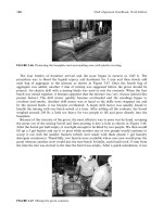
The removal of the coupling hub is accomplished by pulling the hub off the shaft with an
acceptable puller mechanism and at times cooling the shaft with a dry ice pack. Shrink
fit coupling hubs should always have fine threaded puller holes (preferably four) in the end
of the coupling as shown in Figure 4.31.
Bearing-type pullers that ‘‘push’’ the hub off from the backside are not recommended as
there is a great possibility that the puller can twist or pitch slightly preventing a straight axial
draw on the hub. For larger shaft diameters with tight interference fits, it may be necessary to
apply gentle heating to the coupling for removal.
4.9.4 SPLINED SHAFT WITH END LOCK NUT OR LOCKING PLATE
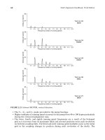
A splined shaft and coupling arrangement is shown in Figure 4.32. There should be a slight
interference fit (0.0005 in.) to prevent backlash or rocking of the hub on the shaft.
4.9.5 TAPERED BORE—INTERFERENCE FIT WITH KEYWAYS
Tapered shaft ends are generally used where high torques and speeds are experienced on
rotating machinery, necessitating a tight coupling hub to shaft fit up. The shaft end is tapered
to provide an easier job of removing the coupling hub.
The degree of taper on a shaft end is usually expressed in terms of its slope (inches per foot).
The amount of interference fit is expressed in inches per inch of shaft diameter. The general
rule for interference fits for this type of shaft arrangement is 1 mil per inch of shaft diameter.
The distance a coupling hub must travel axially along a shaft past the point where the hub is
just touching the shaft at ambient temperatures is found in the following equation:
HT ¼
12I
ST
(4:2)
TABLE 4.4
Guidelines for Shrink Fits on Shafts
Shaft Diameter (in.) Interference Fit (in.)
1/2 to 2
2 to 6
6 and up
0.0005 to 0.0015 in.
0.005 to 0.0020 in.
0.0001 to 0.00035 inches
per inch of shaft diameter
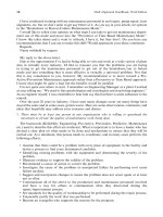
A
B
C
D
Compare A to B and C to D
Coupling
hub
Key
Shaft
FIGURE 4.30 Measuring the shaft and coupling hub for proper fits.
Piotrowski / Shaft Alignment Handbook, Third Edition DK4322_C004 Final Proof page 170 6.10.2006 5:44pm
170 Shaft Alignment Handbook, Third Edition
where HT is the distance the coupling hub must travel to provide an interference fit equal I
(mils), I is the interference fit (mils), and ST is shaft taper (in.=ft).
The procedure for mounting a tapered coupling hub with keys:
1. Mount bracket firmly to coupling hub and slide hub onto shaft end to lightly seat the
hub against the shaft. Insure all surfaces are clean.
2. Measure hub travel gap HT with feeler gauges and lock nut down against bar. Use
Equation 3.2 to determine the correct axial travel needed to obtain the required inter-
ference fit onto the shaft.
3. Remove the coupling hub and puller assembly and place in an oven or hot, clean oil bath
to desired differential temperature. Refer to Equation 4.1 to determine the required
temperature rise to expand the coupling hub.
4. Set key in keyway and insure all contact surfaces are clean and burr free.
5. Carefully slide the heated coupling hub onto the shaft until the center measurement bolt
touches the shaft end and hold in place until hub has cooled sufficiently.
4.9.6 COUPLING HUB TO SHAFT SURFACE CONTACT
One extremely important and often overlooked consideration when working with tapered
shafts and coupling hubs is the amount of surface contact between the shaft and hub. Due to
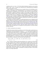
FIGURE 4.31 Coupling hub puller.
FIGURE 4.32 Splined shaft end.
Piotrowski / Shaft Alignment Handbook, Third Edition DK4322_C004 Final Proof page 171 6.10.2006 5:44pm
Flexible and Rigid Couplings 171
slight machining inaccuracies, coupling hubs may not fully contact the shaft resulting in a
poor fit when the hub is shrunk or pressed on in final assembly.
To check the surface contact, apply a thin coat of Prussian blue paste to the inner bore of the
coupling hub with your finger or a soft cloth. Slide the coupling hub axially over the tapered
shaft end until contact is made and rotate the coupling hub about 158 to transfer the paste to the
shaft. Draw the coupling hub off and observe the amount of Prussian blue paste that trans-
ferred from the hub to the shaft (not how much blue came off the inside bore of the coupling
hub). If there is not at least 80% contact, the fit is not acceptable. If the bore discrepancies are
slight, it is possible to lap the surfaces with a fine grit lapping compound. Apply the compound
around the entire surface contact area of the tapered shaft end, lightly pushing the coupling hub
up the taper and rotating the coupling hub alternately clockwise and counterclockwise through
a458 arc. Check the surface contact after 10 or 12 lapping rotations. Continue until surface
contact is acceptable. However if a ‘‘ridge’’ begins to develop on the shaft taper before good
surface contact is made, start making preparations for machining of the shaft and the coupling
hub. It is better to bite the bullet now than try to heat the hub and put it on only to find out that
it does not go on all the way or to pick up the pieces of a split coupling hub after the unit ran for
a short period of time.
4.9.7 KEYLESS TAPER BORES
After working with shafts having keyways to prevent slippage of the coupling hub on the
shaft, it seems very unnerving to consider attaching coupling hubs to shafts with no keys.
Keyless shaft fits are quite reliable and installing hubs by hydraulic expansion methods proves
to be fairly easy if installation and removal steps are carefully adhered to. As the interference
fits are usually ‘‘tighter’’ than found on straight bores or tapered and keyed systems,
determining a proper interference fit will be reviewed.
4.9.8 PROPER INTERFERENCE FIT FOR HYDRAULICALLY INSTALLED COUPLING HUBS
The purposes of interference fits are twofold:
1. Prevent fretting corrosion that occurs from small amounts of movement between the
shaft and the coupling hub during rotation.
2. Prevent the hub from slipping on the shaft when the maximum amount of torque is
experienced during a start up or during high running loads.
For rotating shafts, the relation between torque, horsepower, and speed can be expressed as
T ¼
63,000P
n
(4:3)
where P is the horsepower, T is the torque (in lbs), and n is the shaft speed (rpm).
The maximum amount of shearing stress in a rotating shaft occurs in the outer fibers (i.e.,
the fibers at the outside diameter) and is expressed as
t
max
¼
Tr
J
¼
16T
pd
3
(4:4)
where t
max
is the maximum shear stress (lb=in.), T is the torque (in lbs), r is the radius (in.), d
is the diameter (in.), and J is the polar moment of inertia, J ¼ pr
4
=2 ¼ pd
4
=32.
Piotrowski / Shaft Alignment Handbook, Third Edition DK4322_C004 Final Proof page 172 6.10.2006 5:44pm
172 Shaft Alignment Handbook, Third Edition
The accepted ‘‘safe allowable’’ torsional stress for the three commonly used types of carbon
steel for shafting can be found in Table 4.5.
Therefore the torsional holding requirement for applied torques is expressed as
T ¼
t
max
pd
3
16
(4:5)
The amount of torque needed to cause a press fit hub to slip on its shaft is given by
T ¼
mppLd
2
2
(4:6)
The amount of contact pressure between a shaft and a coupling hub is related to the amount
of interference and the outside diameters of the shaft and the coupling hub and is expressed as
p ¼
IE(DH
2
À DS
2
)
2(DH
2
)(DS)
(4:7)
where p is the contact pressure (lbs=in.
2
), I is the interference fit (mils), E is the modulus of
elasticity (30Â10
6
lb=in. for carbon steel), DH is the outside diameter of coupling hub (in.),
and DS is the outside diameter of shaft (in.).
As the shaft is tapered, dimension DS should be taken on the largest bore diameter on the
coupling hub where the contact pressure will be at its minimum value as shown in Figure 4.34.
Therefore to find the proper interference fit between a coupling hub and a tapered shaft to
prevent slippage from occurring:
1. Determine the maximum allowable torque value for the shaft diameter and the shaft
material.
2. Determine the contact pressure needed to prevent slippage from occurring based on the
maximum allowable torque value found in step 1.
3. Calculate the required interference fit (solve for p in Equation 4.6 and i in Equation 4.7).
4.9.9 INSTALLATION OF KEYLESS COUPLING HUBS USING HYDRAULIC EXPANSION
Installing keyless taper hubs requires some special hydraulic expander and pusher arrange-
ments to install or remove the coupling hub onto the shaft end. Figure 4.35 shows the general
arrangement used to expand and push the hub onto the shaft.
TABLE 4.5
Allowable Torsional Stresses for Shafts
t
max
Allowable Torsional
Stress (psi)
5000
10000
11000
1040
4140
4340
AISI #
Piotrowski / Shaft Alignment Handbook, Third Edition DK4322_C004 Final Proof page 173 6.10.2006 5:44pm
Flexible and Rigid Couplings 173
The procedure for installation of coupling hub using hydraulic expander and pusher
assembly:
1. Check for percentage of surface contact between coupling hub and shaft (must have
80% contact or better).
2. Insure all mating surfaces are clean and that oil passageways are open and clean.
3. Install ‘‘O’’ rings and backup rings in coupling hub and shaft insuring that backup ring
is on ‘‘outside’’ of ‘‘O’’ ring with respect to hydraulic oil pressure. Lightly oil the ‘‘O’’
rings with hydraulic fluid. Place coupling hub (and hub cover) onto shaft.
4. Install expander pump supply line to shaft end. Install the pusher piston assembly onto
the end of the shaft insuring that the piston is drawn back as far as possible. Hook up
the expander pump and begin pumping hydraulic oil through supply line to bleed any
air from expansion ports and expansion groove in shaft. Once the oil has begun to seep
through the coupling hub ends, lightly push the coupling hub against the shaft taper
and begin to pump oil into the pusher piston assembly to seat the piston against the
coupling hub.
5. Place a dial indicator against the backside of the coupling hub and zero the indicator.
6. Start applying pressure to the pusher piston assembly forcing the hub up the taper
(approximately 2000 to 4000 psig).
7. Slowly increase the pressure on the expander pump supply line until the coupling hub
begins to move. The hydraulic pressure on the pusher piston assembly will begin to
drop off as the hub begins to move. Maintain sufficient pressure on the pusher piston
to continue to drive the hub onto the shaft. If the pusher piston pressure drops off
considerably when the expansion process is underway, there is a great potential for the
‘‘O’’ rings to ‘‘blow out’’ the ends of the coupling hub immediately seizing the hub to
the shaft.
FIGURE 4.33 Measuring tool for proper interference fits on tapered shaft ends.
FIGURE 4.34 Shaft and coupling hub outside diameter measurement locations.
Piotrowski / Shaft Alignment Handbook, Third Edition DK4322_C004 Final Proof page 174 6.10.2006 5:44pm
174 Shaft Alignment Handbook, Third Edition
8. Continue forcing the hub up the shaft until the desired amount of hub travel and
interference fit is attained. The expansion pressure will have to attain the required
holding pressure as defined in Equation 4.7.
9. Once the correct hub travel has been achieved, maintain sufficient hydraulic pressure
on the pusher assembly to hold the coupling hub in position and bleed off the pressure
in the expansion system. Allow 15–20 min to elapse while bleeding to insure any
trapped oil has had a chance to escape before lowering the pusher piston pressure.
10. Remove the pusher and expander assemblies.
The removal of the coupling hub is achieved by reversing the installation process. The key to
successful installation is to take your time and not try to push the hub up the shaft end all in
one move.
BIBLIOGRAPHY
Alignment Loading of Gear Type Couplings, Bently Nevada Applications Notes no. (009)L0048, Bently
Nevada Corp., Minden, Nevada, March 1978.
Anderson, J.H., Turbocompressor drive couplings, J. Eng. Ind., ASME, paper no. 60-WA-212, January
1962, pp. 115–123.
Baer, L., Tolerant couplings, Mech. Eng., 111(5), 58–59, 1989.
Bannister, R.H., Methods for modelling flanged and curvic couplings for dynamic analysis of complex
rotor constructions, J. Mech. Des, Trans. ASME, 102(1), 130–139, 1980.
Beard, C.A., The selection of couplings for engine test beds, second Intl. Conf. on Vib. Rotating Mach.,
September 1–4, 1980, Churchill College, Cambridge, UK, C267=80, pp. 115–118.
Bloch, H.P., Why properly rated gears still fail? Hydrocarbon Process., 95–97, 1974.
Bloch, H.P., Less costly turbomachinery uprates through optimized coupling selection, Proc. Fourth
Turbomachinery Symp., Oct. 1975, Gas Turbine Laboratories, Texas A&M University, College
Station, TX, pp. 149–152.
Bloch, H.P., How to uprate turboequipment by optimized coupling selection? Hydrocarbon Process.,
55(1), 87–90, 1976.
Bloch, H.P., Use keyless couplings for large compressor shafts, Hydrocarbon Process., 181–186, 1976.
Bloch, H.P., Improve safety and reliability of pumps and drivers, Part 2—Gear coupling vs nonlubri-
cated couplings, Hydrocarbon Process., 56(2), 123–125, 1977.
Broersma, G. (Ed.), Couplings and Bearings, Part I Couplings, H. Stam, Culemborg, 1968, pp. 1–82.
Brown, H.W., A reliable spline coupling, J. Eng. Ind., Trans. ASME, 101(4), 421–426, 1979.
FIGURE 4.35 Hydraulic expander and pusher assembly.
Piotrowski / Shaft Alignment Handbook, Third Edition DK4322_C004 Final Proof page 175 6.10.2006 5:44pm
Flexible and Rigid Couplings 175
Bu
¨
hlmann, E.T. and Luzi, A., Rotor instability due to a gear coupling connected to a bearingless sun
wheel of a planetary gear, Proc. Rotordynamic Instability Problems in High-Performance Turbo-
machinery, May 16–18, 1988, Texas A&M University, College Station, TX, NASA CP-3026,
pp. 19–39.
Calistrat, M.M., What causes wear in gear type couplings? Hydrocarbon Process., 53–57, 1975.
Calistrat, M.M., Grease separation under centrifugal forces, ASME, paper no. 75-PTG-3, July 3, 1975.
Calistrat, M.M., Metal diaphragm coupling performance, Hydrocarbon Process., 56(3), 137–144, 1977.
Calistrat, M.M., Extend gear coupling life, Part 1, Hydrocarbon Process., 57(1), 112–116, 1978.
Calistrat, M.M., Extend gear coupling life, Part 2, Hydrocarbon Process., 115–118, 1979.
Centrifugal Pumps for General Refinery Services, API Standard 610, American Petroleum Institute,
Washington, D.C., March 1971.
Chander, T. and Biswas, S., Abnormal wear of gear couplings—A case study, Trib. Intl., 16(3), 141–146,
1983.
Counter, L.F. and Landon, F.K., Axial vibration characteristics of metal-flexing couplings, Proc. Fifth
Turbomachinery Symp., Oct. 1976, Gas Turbine Laboratories, Texas A&M University, College
Station, TX, pp. 125–131.
Dewell, D.L. and Mitchell, L.D., Detection of a misaligned disk coupling using spectrum analysis,
J. Vib., Acoust., Stress, Rel. Des., Trans. ASME, 106(1), 9–16, 1984.
Eshleman, R.L., The role of sum and difference frequencies in rotating machinery fault diagnosis, second
Intl. Conf. on Vib. Rotating Mach., Sept. 1–4, 1980, Churchill College, Cambridge, UK,
C272=80, pp. 145–149.
Finn, A.E., Instrumented couplings: The what, the why, and the how of the indikon hot-alignment
measurement system, Proc. Ninth Turbomachinery Symp., Dec. 1980, Texas A&M University,
College Station, TX, pp. 135–136.
Foszcz, J.L., Couplings—they give and take, Plant Eng., 42(18), 53–57, 1988.
Gensheimer, J.R., How to design flexible couplings? Mach. Des., 33(19), 154–159, 1961.
Gibbons, C.B., Coupling misalignment forces, Proc. Fifth Turbomachinery Symp., Oct. 1976, Gas
Turbine Laboratories, Texas A&M University, College Station, TX, pp. 111–116.
Gooding, F.E., Types and kinds of flexible couplings, Industrial Engineer, 529–533, 1923.
Goody, E.W., Laminated membrane couplings for high powers and speeds, Intl. Conf. on Flexible
Couplings, June 29–July 1, 1977, High Wycombe, Bucks, England.
Hunt, K.H., Constant-velocity shaft couplings: A general theory, J. Eng. Ind., Trans. ASME, 95(2),
455–464, 1973.
Kamii, N. and Okuda, H., Universal joints applied to hot strip mill drive lines, Iron Steel Eng., 52(12),
52–56, 1975.
Kato, M., et al., Lateral-torsional coupled vibrations of a rotating shaft driven by a universal joint,
JSME Intl. J., Ser. III, 31(1), 68–74, 1988.
Kirk, R.G., et al., Theory and guidelines to proper coupling design for rotor dynamics considerations,
J. Vib., Acoust., Stress, Rel. Des., Trans. ASME, 106(1), 129–138, 1984.
Kojima, H. and Nagaya, K., Nonlinear torsional vibrations of a rotating shaft system with a magnet
coupling, Bull. JSME
, 27(228), 1258–1263, 1984.
Loosen, P. and Prause, J.J., Frictional shaft—hub connectors—analysis and applications, Design Eng.,
January 1974.
Mancuso, J.R., Moments and forces imposed on power transmission systems due to misalignment of a
crown tooth coupling, Master’s Thesis, Pennsylvania State University, Hershey, PA, June 1971.
Mancuso, J.R., A New Wrinkle to Diaphragm Couplings, ASME, paper no. 77-DET-128, June 24,
1977.
Mancuso, J.R., The manufacturer’s world of coupling potential unbalance, Proc. 13th Turbomachinery
Symp., November 1984, Texas A&M University, College Station, TX, pp. 97–104.
Mancuso, J.R., Disc vs diaphragm couplings, Mach. Des., 58(17), 95–98, 1986.
Mancuso, J.R., Couplings and Joints, Marcel Dekker, New York, 1986. [ISBN #0–8247–7400–0]
Marmol, R.A., et al., Spline coupling induced nonsynchronous rotor vibrations, J. Mech. Des, Trans.
ASME, 102(1), 168–176, 1980.
Piotrowski / Shaft Alignment Handbook, Third Edition DK4322_C004 Final Proof page 176 6.10.2006 5:44pm
176 Shaft Alignment Handbook, Third Edition
Maxwell, J.H., Vibration analysis pinpoints coupling problems, Hydrocarbon Process., 59(1),
95–98, 1980.
McCormick, D., Finding the right flexible coupling, Des. Eng., 52(10), 61–66, 1981.
Milenkovic, V., A new constant velocity coupling, J. Eng. Ind., Trans. ASME, 99(2), 367–374,
1977.
Miller, F.F., Constant-velocity universal ball joints, Mech. Des., 37(9), 184–193, 1965.
Oberg, E., Jones, F.D., and Horton, H.L., Machinery’s Handbook, 21st ed., Industrial Press Inc.,
New York, 1980.
Ohlson, J.F., Coupling of misaligned shafts, US PATENT, 4187698, February 1980.
Ota, H. and Kato, M., Even multiple vibrations of rotating shaft due to secondary moment of a
universal joint, Third Intl. Conf. on Vib. Rotating Mach., Sept. 11–13, 1984, University of
York, UK, C310=84, pp. 199–204.
Pahl, G., The operating characteristics of gear-type couplings, Proc. Seventh Turbomachinery Symp.,
Dec. 1978, Gas Turbine Labs, Texas A&M University, College Station, TX, pp. 167–173.
Patterson, C., et al., Vibration aspects of rolling mill horizontal drives with reference to recent coupling
development, second Intl. Conf. on Vib. Rotating Mach., Sept. 1–4, 1980, Churchill College,
Cambridge, UK, C297=80, pp. 315–320.
Peeken, H., et al., A new approach to describe the mechanical performance of flexible couplings in drive
systems, Proc. Intl. Conf. Rotordynamics, Sept. 14–16, 1986, Tokyo, Japan, pp. 159–163.
Phillips, J. and Vowles, B., Flexible metallic couplings, Pump Compressors for Offshore Oil Gas Conf.,
June 29–July 1, 1976, University of Aberdeen, UK, C135=76, pp. 103–108.
Potgieter, F.M., Cardan universal joints applied to steel mill drives, Iron Steel Eng., 46(3), 73–79,
1969.
Prause, J.J., New clamping device for fastening pulley end discs to shafts, Skillings Mining Rev.,
68(24), 1979.
Proc. Intl. Conf. on Flexible Couplings for High Powers and Speeds, June 29–July 1, 1977, University of
Sussex, England.
Schwerdlin, H., Reaction forces in elastomeric couplings, Mach. Des., 51(16), 76–79, 1979.
Schwerdlin, H. and Eshleman, R., Combating vibration with mechanical couplings, Mach. Des., 52(20),
67–70, 1980.
Schwerdlin, H. and Eshleman, R., Improve coupling selection through torsional vibration modeling,
Power Transm. Dec., 23(2), 56–59, 1981.
Schwerdlin, H. and Eshleman, R.L., Measuring vibrations for coupling evaluation, Plant Eng., 36(12),
111–114, 1982.
Schwerdlin, H. and Roberts, C., Jr., Combating heat in U-joints, Mach. Des., 53(17), 83–86, 1981.
Seneczko, Z., Tailoring drive output with elastomeric couplings, Mach. Des., 57(7), 123–125, 1985.
Serrell, J.J., Flexible couplings, Machinery, 91–93, 1922.
Shaw, G.V., Employing limited end play couplings saves motor bearings—sometimes, Power, 120–121,
1955.
Shigley, J.E. and Mischke, C.R. (Eds.), Standard Handbook of Machine Design, McGraw-Hill, New-
York, 1986, pp. 29.1–29.38, chap. 29.
Spector, L.F., Flexible couplings, Mach. Des., 30(22), 102–128, 1958.
Wattner, K.W., High speed coupling failure analysis, Proc. Fourth Turbomachinery Symp., Oct.
1975,Gas Turbine Labs, Texas A&M University, City Station, TX, pp. 143–148.
Weatherford, W.D., Jr., et al., Mechanisms of wear in misaligned splines, J. Lub. Tech., Trans. ASME,
90(1), 42–48, 1968.
Williams, R.H., Flexible coupling, US PATENT, 4203305, May 1980.
Winkler, A.F., High speed rotating machinery unbalance, coupling or rotor, Proc. Mach. Vib. Monit.
Ann. Mtg., Apr. 19–21, 1983, Houston, TX, pp. 75–80.
Wireman, T., A fitness plan for flexible couplings, Power Transm. Des., 25(4), 20–22, 1983.
Woodcock, J.S., Balancing criteria for high speed rotors with flexible couplings, Intl. Conf. Vib. Noise in
Pump, Fan and Compressor Installations, Sept. 16–18, 1975, University of Southampton, UK,
C112=75, pp. 107–114.
Piotrowski / Shaft Alignment Handbook, Third Edition DK4322_C004 Final Proof page 177 6.10.2006 5:44pm
Flexible and Rigid Couplings 177
Wright, J., Which shaft coupling is best—lubricated or nonlubricated? Hydrocarbon Process., 54(4),
191–193, 1975.
Wright, C.G., Tracking down the cause of coupling failure, Mach. Des., 49(14), 98–102, 1977.
Zirkelback, C., Couplings—a user’s point of view, Proc. Eighth Turbomachinery Symp., Nov. 1979,
Texas A&M University, College Station, TX, pp. 77–81.
Piotrowski / Shaft Alignment Handbook, Third Edition DK4322_C004 Final Proof page 178 6.10.2006 5:44pm
178 Shaft Alignment Handbook, Third Edition
5
Preliminary Alignment Checks
In Chapter 1, we examined the eight basic steps of aligning rotating machinery. This chapter
will cover in detail the tasks identified in step 4, conducting and performing any preliminary
checks before starting the alignment. Perhaps the most overlooked step in the process of
aligning rotating machinery is this one.
All too often, people who skip this step find themselves having problems in measuring the
off-line shaft positions accurately, adding and then removing shim stock several times under
the machinery feet, and they frequently find themselves ‘‘chasing their tail,’’ trying to
reposition the machines laterally several times with marginal or no success. After wasting
several hours in their attempt to align the machinery, they realize that something is wrong and
they go back to check for many of the problems discussed herein.
In summary, you will be trying to find and correct any problems in the following areas:
.
Unstable or deteriorated foundations and base plates
.
Damaged or worn components on the rotating machinery (e.g., machine casings, bear-
ings, shafts, seals, couplings)
.
Excessive runout conditions (e.g., bent shafts, improperly bored coupling hubs)
.
Machine casing to base plate interface problems (e.g., soft foot)
.
Excessive piping, ductwork, or conduit forces
Some of the items mentioned above are related very closely to the information given in
Chapter 3 on foundations, base plates, sole plates, and piping strain and so it is recommended
that you review this chapter. As discussed in Chapter 1, a considerable amount of time can be
spent on these preliminary checks and corrections. In fact, I typically spend much more time
for performing these tasks it takes to actually align the machinery. Many of the problems may
be time consuming, expensive, and difficult to correct. Because of this, there is a great
tendency to come up with excuses for not doing it.
5.1 FOUNDATION AND BASE PLATE CHECKS
With respect to the successful long-term operation of the machinery, an outstanding align-
ment job can quickly deteriorate if the equipment is perched on unstable frames, inertia
blocks, or foundations. Chapter 3 discussed about what desired design features should be
incorporated into foundations and base plates but these features may not necessarily exist on
the machinery that is worked on. Therefore the first place of looking for problems would be in
the supporting structure for the machinery. A quick review of Figure 3.19 through Figure 3.25
will show examples of what to check for and correct.
Piotrowski / Shaft Alignment Handbook, Third Edition DK4322_C005 Final Proof page 179 26.9.2006 8:36pm
179
5.2 DIAL INDICATOR BASICS
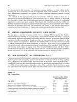
Since the use of dial indicators will be discussed frequently in this chapter, Figure 5.1 shows
the basic operating principle of this versatile measurement tool. It is highly recommended to
get familiar with this device since it will be used for a wide variety of tasks in the overall
process of machinery installation, troubleshooting, problem solving, and shaft alignment.
5.3 DAMAGED, WORN, OR IMPROPERLY INSTALLED MACHINERY
COMPONENT CHECKS
Every once in a while, you may have the pleasure of installing brand new rotating machinery.
If you are in the construction industry that is primarily what you will be doing. However, in a
maintenance organization, you will very likely be working with equipment that has been in
service for sometime and invariably it is required to find and correct a problem with the
0
50
10
40
20
30
+
_
10
40
20
30
0
50
10
40
20
30
+
_
10
40
20
30
Bottom plunger type Back plunger type
Dial indicator basics
0
50
10
40
20
30
+
_
10
40
20
30
−70
−25
+40
+75
Stem mov
es outward
Needle rotates counter
clockwise
Stem moves inward
Needle moves clockwise
0
50
10
40
20
30
+
_
10
40
20
30
0
50
10
40
20
30
+
_
10
40
20
30
0
50
10
40
20
30
+
_
10
40
20
30
0
50
10
40
20
30
+
_
10
40
20
30
FIGURE 5.1 Dial indicator basic operation.
Piotrowski / Shaft Alignment Handbook, Third Edition DK4322_C005 Final Proof page 180 26.9.2006 8:36pm
180 Shaft Alignment Handbook, Third Edition
equipment. Chapter 1 discussed the four different maintenance philosophies. The ultimate
goal of a quality maintenance group is to achieve proactive or prevention maintenance status.
The capacity to detect ensuing problems with machinery, stop the damage before it becomes a
financial loss to the company, have the capability to quickly detect the problems with the
equipment, and engineer the corrective measures to prevent the malady from occurring again
is the ultimate goal. Very few people have been able to attain this level of performance. This
chapter discusses many of the tasks that make the difference between run-to-failure mainten-
ance and proactive or preventive maintenance.
If machinery has been operating for sometime, the bearings that support the rotor may
have sustained some damage and it is suggested that some checks should be made to insure
that the bearings are in good working order. One of the simplest tests that can be performed is
a shaft ‘‘lift check’’ as shown in Figure 5.2 and Figure 5.3.
Positioning a dial indicator on top of the shaft as close as to get it to the inboard bearing, it
is essential to anchor the indicator to a stationary object with a magnetic base or a clamp.
Then lifting the shaft upward enough to detect if any motion occurs, but not with so much
force as to permanently deform the shaft, can easily happen by using a hydraulic piston, chain
hoist, or overhead crane.
If the shaft is supported in rolling element-type bearings as shown in Figure 5.4, the amount
of lift on the shaft should be negligible (i.e., 0 to maybe 1 mil). If there is an excess amount of
shaft lift with a rolling element bearing, four possible reasons for this is as follows:
1. The inner race of the bearing is loose on the shaft.
2. There is too much clearance between the rolling elements and the inner and outer
raceways.
3. The outer race is loose in its housing.
4. A combination of two or more of the items above.
Shaft lift check
Lift upward on each shaft and note
the dial indicator readings
Place the indicators on top of the shaft or coupling
hub and hold the dial indicators steady
FIGURE 5.2 How to perform a shaft lift check.
Piotrowski / Shaft Alignment Handbook, Third Edition DK4322_C005 Final Proof page 181 26.9.2006 8:36pm
Preliminary Alignment Checks 181
If the inner race is loose on the shaft, the inner race will begin ‘‘skidding’’ on the shaft,
eventually damaging the shaft (if it has not already done so). If this condition exists, the
machine’s running is stopped immediately and the bearing is removed to make a thorough
inspection of the shaft, bearing, and bearing housing. The shaft and the bearing have to be
replaced.
If there is too much clearance between the rolling elements and the inner and outer
raceways, the rollers will begin skidding on the raceways, eventually damaging the bearing
(if it has not already done so). If this condition exists, the machine’s running is stopped
immediately and the bearing is removed to make a thorough inspection of the shaft, bearing,
and bearing housing. The shaft and the bearing have to be replaced.
FIGURE 5.3 Performing a lift check on a pump shaft.
Rolling element bearings began to appear in the
early 1900'
s and are also referred to as antifriction or
ball bearings. The bearing consists of an inner race,
rolling elements, and an outer race. Sometimes the
rolling elements are held in place with a
cage assembly. As the shaft turns, a film of
lubricant forms between the rolling elements and
the raceways. The oil film thickness can range
between1 and 3 µm (4 to 12 millionths of an inch)
and the oil pressures at the minimum oil film
thickness are very high (approximately 40 kpsi).
If the oil film breaks down, metal to metal contact
between the rolling elements and the raceways can
occur causing damage to the bearing. Damage to the
rolling elements, raceways, or cage assembly can be
detected through vibration analysis.
Inner
race
Outer race
Rolling elements
FIGURE 5.4 Rolling element bearing design.
Piotrowski / Shaft Alignment Handbook, Third Edition DK4322_C005 Final Proof page 182 26.9.2006 8:36pm
182 Shaft Alignment Handbook, Third Edition
If there is too much clearance between the outer race and the housing, the outer raceway
will begin skidding on inside the housing and eventually damaging the housing (if it has not
already done so). If this condition exists, the machine’s running is stopped immediately and
the bearing is removed to make a thorough inspection of the shaft, bearing, and bearing
housing. The bearing housing and machine case have to be replaced.
There are other types of ‘‘fixes’’ possible for items 1 and 3 (i.e., loose inner or outer race)
but they are usually not recommended for long-term satisfactory performance. It may be
tempting to use epoxy-based adhesives between the raceway and shaft or raceway and
housing but that is not the best corrective measure. Sounds like a good idea until you have
to remove the bearing at some later date. It may be tempting to sleeve the shaft or the housing
but that is also not the best corrective measure. The ability to make a sleeve to achieve the
correct interference fits enables to fix the sleeve correctly in the first place. It is recommended
to consult the equipment manufacturer for the correct procedure for installing new bearings
and the proper type and amount of lubricant to use for that bearing.
If the shaft is supported in sliding-type bearings, the amount of lift on the shaft should be
within the acceptable radial bearing clearance range. Figure 5.5 shows the basic operating
principle of sliding-type bearings. As noted in Figure 5.5, the ‘‘rule of thumb’’ for radial
bearing clearance should be from 3=4 to 2 mils=in. of shaft diameter for oil-lubricated babbit
bearings. If the amount of lift is greater than the maximum clearance for that shaft diameter,
the bearing should be removed and inspected. With cylindrical sliding-type bearings, another
Radial (aka diametral) bearing
clearance should range from 3/4
to 2 mils/in. of shaft diameter
(e.g., a 4 in. diameter shaft should have
a clearance range of 0.003 to 0.008 in.)
Measure with
Plastigage up to
8 mils and soft solder
above 8 mils
Radial (aka
diametral) bearing
clearance
These are the oldest bearings known to man
dating back thousands of years. As the
shaft rotates, a wedge of oil forms between
the shaft and the bearing surfaces lifting the
shaft upwards. Once the oil wedge is formed,
the shaft moves slightly to one side and does
not run in the exact center of the bearing.
The minimum oil film thickness occurs at a
line drawn through the shaft and bearing
centerlines called the shaft attitude angle.
The minimum oil film thickness can range
from 0.3 to 2 mils and acts as a damping medium
for small amounts of shaft motion (vibration)
The lubricant used in rotating machinery is typically
oil but the lubricant could really be any fluid
(compressible or incompressible,
e.g., water or nitrogen) under varying circumstances
or, for environmental reasons.These bearings
are also known as :
• Hydrodynamic bearings
• Plain bearings
• Journal bearings
• Sleeve bearings
• Babbit bearings
Babbit
(lead−tin alloy)
HousingLubricant
Shaft
Shaft
“attitude”
angle
FIGURE 5.5 Sliding bearing design.
Piotrowski / Shaft Alignment Handbook, Third Edition DK4322_C005 Final Proof page 183 26.9.2006 8:36pm
Preliminary Alignment Checks 183
recommended method for checking bearing clearance is given in Figure 5.6. Plastigage or soft
solder can be used for the clearance check. In addition to the clearance check, a ‘‘tilt and
twist’’ check should be made as shown in Figure 5.7. The tilt and twist checks are performed
to determine if the centerline of the bore of the bearing is parallel to the centerline of rotation
of the shaft in the up and down (tilt) and side-to-side (twist) direction. An alternative check is
a ‘‘blue check’’ where a thin coat of Prussian bluing is applied to the lower half of the bearing.
The bearing is then installed into its lower hemisphere, and the shaft is lowered onto the
bearing and then lifted to allow the removal of the lower half of the bearing. The bearing is
then examined to determine how much of the bluing is transferred to the shaft to insure that
there is at least 80% shaft to bearing contact. Figure 5.8 shows a bearing in the process of blue
checked. Bearing in mind that blue checking will determine if there is a tilt problem but not
necessarily a twist problem.
Some bearings are spherically seated in their housing to hopefully compensate for any tilt
and twist conditions. Figure 5.9 shows an arrangement for a large steam turbine bearing
Sliding bearing clearance checks
Radial (aka diametral) bearing clearance should range from
3/4 to 2 mils/in. of shaft diameter (e.g., a 4 in. diameter shaft
should have a clearance range of 0.003 to 0.008 in.)
Remove the upper bearing
half and place some
Plastigage or soft solder on
the top of the shaft
Upper bearing housing
Lower bearing half
Upper bearing half
Bearing pedestal or machine case
Radial (aka diametral)
bearing clearance
Shaft
Install the upper bearing
half and tighten the bolts to
the appropriate value
Remove the upper bearing
half and measure the width of the
Plastigage or thickness
of the soft solder
FIGURE 5.6 Sliding bearing clearance checks.
Piotrowski / Shaft Alignment Handbook, Third Edition DK4322_C005 Final Proof page 184 26.9.2006 8:36pm
184 Shaft Alignment Handbook, Third Edition
Tilt and twist in a sliding bearing
Remove the upper
bearing half and
place some Plastigage
or soft solder on
the top of the shaft
Install the upper
bearing half and
tighten the bolts to
the appropriate value
Remove the upper
bearing half and measure the
width of the Plastigage
or thickness of the soft
solder at both ends. If the
thickness is not the same,
a tilt condition exists
Bearing is in a tilted position Bearing is in a twisted position
Remove the upper bearing half and
measure the gaps on both sides
of the shaft at the front and back of
the bearings with feeler gauges
Gap? Gap?
Gap? Gap?
If all four gaps are not the same amount
and equal to half of the total radial bearing
clearance, a twist condition exists
FIGURE 5.7 Finding a tilt and twist problem in a sliding bearings.
FIGURE 5.8 Checking contact on a sliding bearing with bluing.
Piotrowski / Shaft Alignment Handbook, Third Edition DK4322_C005 Final Proof page 185 26.9.2006 8:36pm
Preliminary Alignment Checks 185
where the bearing assembly is held in position with three support blocks. Shims can be added
or removed from each support block to position the bearing in the vertical and lateral
directions and to allow for a small amount of clearance to enable the bearing and pads to
pivot in the spherically shaped housing.
A shaft supported in sliding-type radial bearings can float axially and therefore requires
some device (or force) to maintain its correct axial position. In electric motors supported in
sliding-type radial bearings, the electromagnetic force centers the armature in the housing.
This is often referred to as magnetic center or ‘‘mag center.’’ To find mag center, it is
necessary to disconnect the coupling between the motor and what it is driving, and to start
the motor up and run it ‘‘solo.’’ When the motor has attained its normal operating speed, it is
advised to scribe a line with a felt tip pen or soap stone onto the rotating shaft (care should be
taken while doing this) near the inboard bearing using the seal housing or another stationary
object on the motor as a reference point. The motor is de-energized (i.e., shut down) and to
stop the armature from rotating. After properly safety tagging the breaker, the armature is
rotated by hand and as it is rotating, the armature in the axial direction is pushed or pulled
until the scribed line that was made on the shaft aligns with the selected stationary reference.
This is where the armature wants to run under normal operating conditions. This will become
important later on during the alignment process to get the correct axial position between the
shafts.
Other rotating machines supported in sliding-type radial bearings do not have an electro-
magnetic force to center the shaft like motors do. So a thrust bearing is used. There are three
major components to a thrust bearing:
45˚
Shims
Lower bearing half
Machine housing
Shaft
Upper bearing half
Upper bearing retainer
FIGURE 5.9 Spherically seated sliding bearing on adjustable support blocks.
Piotrowski / Shaft Alignment Handbook, Third Edition DK4322_C005 Final Proof page 186 26.9.2006 8:36pm
186 Shaft Alignment Handbook, Third Edition
1. The thrust runner or thrust disk: This is a disk permanently attached to the shaft.
2. An active thrust bearing: This is the bearing that the thrust runner typically seats against
while it is operating. A film of lubricant prevents the thrust runner from wearing the
thrust bearing out.
3. An inactive thrust bearing: It looks the same as the active thrust bearing and under normal
operation the thrust runner never seats against it, since most machinery wants to thrust in
one direction only. However, if the shaft wants to move in the opposite direction, this
bearing will stop the shaft before it contacts something stationary in the machine.
Some of the most catastrophic failures of machinery have occurred due to a thrust-bearing
failure or due to improperly installing and setting the correct thrust-bearing clearance. To
check this clearance, it is essential to position a dial indicator on the end of the shaft (or
coupling hub) and anchor the indicator to a stationary object with a magnetic base or a
clamp. The shaft toward the operator is pulled until it seats against one of the thrust bearings
and zero the indicator as shown in Figure 5.10. The shaft away from the operator is pushed
until it seats against the other thrust bearing as shown in Figure 5.11. This is repeated for two
or three times and the amount of indicator travel each time is observed. Typically, the thrust-
bearing clearance is somewhere between 15 and 40 mils but it is recommended to consult the
equipment manufacturer for the correct thrust-bearing clearance and the procedure to correct
it if it is not within the recommended range.
Figure 5.12 shows a lower half of a tilt pad-type sliding bearing. Notice that there is some
evidence of wear in the pads. With tilt pad-type sliding bearings, a mandrel (a cylindrical bar
machined to the same outside diameter as the shaft) is used in concert with a dial indicator for
the clearance check. This can be done on a table and the procedure is the same as the shaft lift
check except that the mandrel is placed in a vertical position, the assembled bearing is slid
FIGURE 5.10 Performing a thrust-bearing clearance check, step 1.
Piotrowski / Shaft Alignment Handbook, Third Edition DK4322_C005 Final Proof page 187 26.9.2006 8:36pm
Preliminary Alignment Checks 187
over the mandrel, and a dial indicator is positioned against the bearing and then anchored to
the table. The bearing is then moved toward and away from the dial indicator to measure the
clearance.
The radial bearing clearances mentioned above are not for all types of sliding-type bear-
ings. Water-lubricated ‘‘cutlass’’-type bearings have greater clearances. New cutlass bearings
typically have clearance between 15 and 20 mils and maximum clearances typically should not
exceed 80 mils. With these types of bearings, clearance checks can be made with feeler gauges
at four points around the circumference of the bearing. A cutlass bearing with excessive
clearance on a dredge drive shaft is shown in Figure 5.13. Figure 5.14 shows the feeler gauge
readings on that bearing, indicating an excessive amount of clearance. Notice that there seems
to be a twist problem with this bearing. The condition and fit of bearings is extremely
FIGURE 5.11 Performing a thrust-bearing clearance check, step 2.
FIGURE 5.12 Lower half of a tilt pad-type sliding bearing.
Piotrowski / Shaft Alignment Handbook, Third Edition DK4322_C005 Final Proof page 188 26.9.2006 8:36pm
188 Shaft Alignment Handbook, Third Edition
important in rotating machinery and should be one of the first items that should be checked
before alignment but there are other components that need to be examined for mechanical
integrity.
In a large majority of rotating machinery, some type of fluid or gas is present inside the
machine case and unless it is sealed properly, the fluid or gas will leak out. The lubricant in the
bearings can also leak out if proper sealing is not achieved. Sensory clues are the first sign of
trouble with seals. If one can notice the seeping out of oil from the machine case under the
shaft or oil on the base plate, it is a sign that leakage is occurring.
Air or steam leaks frequently can be audibly detected (sound). Frequently high-pressure
leaks can be outside the range of human detection and may require leak detection sensors and
FIGURE 5.13 Cutlass-type water bearing with excessive clearance.
0.145Љ
0Љ
0.037Љ 0.098Љ
Diesel side Pump side
0.198Љ
0Љ
0.125Љ 0Љ
FIGURE 5.14 Measured clearances on above bearing.
Piotrowski / Shaft Alignment Handbook, Third Edition DK4322_C005 Final Proof page 189 26.9.2006 8:36pm
Preliminary Alignment Checks 189
equipment to be located. The typical range for hearing for humans is from 20 to 20,000 Hz
(1 Hz ¼ 1 cycle per second).
To contain compressible or incompressible fluids inside a machine case, there are four most
commonly used types of shaft seals: labyrinth, lip, mechanical, and packing. Figure 5.15
shows the basic design of each of these seals. Although these seals are shown with an
overhung centrifugal pump, they are used on a wide variety of rotating machinery. Figure
5.15 illustrates how to prevent the fluid that is pumped from leaking out along the shaft by
employing the two most common sealing methods of either mechanical packing or mechan-
ical seals.
Mechanical packing consists of flexible rings that look like braided rope with a square cross
section. The packing rings are inserted into a cylindrical cavity surrounding the shaft called
the ‘‘stuffing box’’ as shown on the top part of the shaft in Figure 5.15. Frequently three
packing rings are inserted. A device called the ‘‘lantern ring’’ contains three more packing
rings. The packing gland is then bolted to the pump housing to compress the packing rings to
provide the seal. The mechanical packing was never meant to provide a perfect seal and some
leakage should occur just to keep a film of fluid between the packing rings and the shaft,
otherwise the packing will eventually wear away the shaft. Although it is not shown in the
diagram, a sacrificial shaft sleeve is often installed in this area so that the packing does not
damage the shaft itself. A hole is bored through to the stuffing box area where the lantern ring
is located. This is used to inject a fluid (frequently the process fluid itself) into the stuffing box
to provide the lubricating film between the packing and the shaft or shaft sleeve.
Mechanical seals consist of a stationary seal ring and a rotating seal ring as shown on the
bottom part of the shaft in Figure 5.15. There are a variety of designs incorporating one or
two sealing ring sets. The mating faces of the sealing rings are ground flat and have a very
Packing
Lantern ring
Packing gland
“Stuffing box” area
Rotating seal
Stationary seal
Spring
O-rings
Lip seal
Labyrinth seal
FIGURE 5.15 (See color insert following page 322.) Four commonly used seals in rotating machinery.
Piotrowski / Shaft Alignment Handbook, Third Edition DK4322_C005 Final Proof page 190 26.9.2006 8:36pm
190 Shaft Alignment Handbook, Third Edition
smooth surface finish (frequently 4 rms or better). To keep the faces together a spring (or
springs) is employed. Again, this needs to be a film of fluid between the rotating and
stationary seal faces. The design premise of a mechanical seal is that as the process fluid
attempts to traverse across the mating seal faces, by the time it gets to the outside world, the
fluid has vaporized. For processes where the vapors could be harmful, double seals are
typically used and a nonvolatile ‘‘barrier fluid’’ is injected into the stuffing box area.
To insure successful sealing capabilities, it is important to insure that the shaft is centered in
the stuffing box or seal housing. For the pump shown in Figure 5.15, assuming the bolt-hole
patterns for the bearing housing and the stuffing box housing were machined concentric to
the bearing bores and that the shaft is not bent, the clearance between the outside of the shaft
and the bore of the stuffing box should be the same all the way around. Usually this is true,
but not always. In other pump designs, however, the bearing housing is not part of concen-
trically machined housings and may not ‘‘automatically’’ be centered to the bore of the
stuffing box. In either case, it may be wise to check the concentricity of the stuffing box.
To determine if the shaft is centered, the distance from the outside surface of the shaft to
the inside bore of the seal housing is measured at four points 908 apart. These measurements
can be taken in a number of different ways. Feeler gauges, snap gauges, and in some cases, a
magnetic base and a dial indicator can be used for the measurements. Figure 5.16 shows a
snap gauge that is used to measure the distance between the outside surface of a pump shaft
and the bore of the stuffing box where packing is used to seal the water inside the pump.
Figure 5.17 shows the initial measurements taken on this pump. The pump shaft is lowered
toward the east. On this particular pump, the bearing housing has to be positioned to center
the shaft in the stuffing box before aligning the pump to its driver.
In addition to keeping the process fluid from leaking out along the shaft, the bearing
lubricant needs to be present in the bearing housing with seals. Figure 5.15 shows two of the
FIGURE 5.16 Snap gauge used to measure stuffing box clearance.
Piotrowski / Shaft Alignment Handbook, Third Edition DK4322_C005 Final Proof page 191 26.9.2006 8:36pm
Preliminary Alignment Checks 191
more commonly used lubricant seals: lip seals and labyrinth seals. Lip seals are frequently
made of rubber and can easily be installed backwards if care is not taken. While performing
the preliminary checks on a motor and pump drive, it was observed that an oil seal was
installed backward on the electric motor as shown in Figure 5.18.
Since rotating machinery is likely to exhibit some vibration during operation, there is a
possibility that the integrity of the housing can degrade over moderate to long periods of time.
High-stress concentration areas will begin to cyclically fatigue and cracks may begin to form
and then propagate. A complete visual inspection of the machine casing and housing may
uncover problem areas. Figure 5.19 shows where a crack was found on a machine housing
during a visual inspection. Cracks can be very difficult to visually detect without help and die
penetrant checks may be warranted.
Stuffing box
Pump shaft
1.118Љ
0.985Љ
1.046Љ
1.003Љ
West East
FIGURE 5.17 Stuffing box clearance measured on pump in Figure 5.16.
FIGURE 5.18 Oil seal installed backwards on a motor.
Piotrowski / Shaft Alignment Handbook, Third Edition DK4322_C005 Final Proof page 192 26.9.2006 8:36pm
192 Shaft Alignment Handbook, Third Edition
For machinery that has been operating for some period of time, it is also suggested that a
visual inspection be made of the coupling (flexible or rigid) for wear or problem areas. Figure
5.20 shows excessively worn teeth on a gear coupling. Elastomeric couplings will degrade
rapidly under moderate to severe misalignment conditions. Figure 5.21 shows extreme wear
on a new elastomeric coupling which had been subjected to 20þ mils=in. of misalignment that
occurred over a period of just 30 weeks of intermittent operation.
FIGURE 5.19 Cracked weld on machine housing.
FIGURE 5.20 Excessively worn gear coupling.
Piotrowski / Shaft Alignment Handbook, Third Edition DK4322_C005 Final Proof page 193 26.9.2006 8:36pm
Preliminary Alignment Checks 193
5.4 RUNOUT
The term ‘‘runout’’ describes a condition where a rotating object is not concentric or
perpendicular with its centerline of rotation. Runout is also referred to as an ‘‘off center’’
or ‘‘eccentric’’ condition and should be one of the first things to check on the machinery that
is attempted to be aligned. All rotating machinery shafts, or any device that is attached to a
shaft such as coupling hubs, shaft sleeves, impellers, fan blades, armature windings, gears,
blades, shrouds, or other types of components rigidly attached to shafts, will exhibit some
runout condition. There is runout in just about anything and everything that rotates and it is
just a matter of how much runout is present. Some runout can be as small as 10 millionths of
an inch or as high as 100 mils or greater.
Runout checks are standard operating procedures when assembling components onto a
rotating shaft. First the shaft itself is checked and then each component that is rigidly
attached to the shaft is checked for excessive runout conditions. Moderate to excessive runout
will cause moderate to excessive vibration in the machinery where the greatest amount of
vibration will appear at the running speed of the machine making it appear as an ‘‘out-of-
balance’’ condition. In many cases, it is not wise to attach balance correction weights to
reduce the vibration. The correction weights may reduce the dynamic forces that are causing
the vibration but they will not reduce or remove the eccentricity condition. If an internal
rotating part such as a pump impeller has excessive runout, the balance correction weights
will reduce the dynamic forces but the eccentric impeller may contact a stationary object
inside the pump case, potentially causing a catastrophic failure when the unit is started or
later when it reaches operating conditions.
Rotating equipment manufacturers understand this and are very careful to insure that
excessive runout does not cause rub conditions. However, the majority of rotating machinery
is shipped to its final destination without the power transmission device (e.g., coupling hub or
V-belt sheave) attached to the end of its shaft. This is most often installed on the machine at
the factory where the equipment will be used in production. All too often, runout checks are
not made when these parts are placed at the end of a shaft. The runout problems that occur
with the power transmission device (e.g., coupling hub or V-belt sheave) will be discussed in
detail.
There are two basic types of runout conditions, radial and face runout. Radial runout
quantifies the eccentricity of the outer surface of a shaft or a component rigidly attached to a
shaft with respect to the shaft’s centerline of rotation. Face runout quantifies the amount of
nonperpendicularity that may exist at the end of a shaft or on surfaces of components rigidly
attached to a shaft. Runout conditions are typically measured with dial indicators as illus-
trated in Figure 5.22. Runout checks should also be made at several points along the length of
FIGURE 5.21 Excessively worn elastomeric coupling.
Piotrowski / Shaft Alignment Handbook, Third Edition DK4322_C005 Final Proof page 194 26.9.2006 8:36pm
194 Shaft Alignment Handbook, Third Edition