Handbook of Shaft Alignment Part 14 docx
Bạn đang xem bản rút gọn của tài liệu. Xem và tải ngay bản đầy đủ của tài liệu tại đây (1.57 MB, 50 trang )
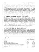
One way to accomplish this measurement is to perform the double radial method (refer to
Chapter 12). As shown in Figure 19.4, the dial indicator measurements can be taken on the
inside bore of a cylinder rather than capturing the measurements on the outside of a cylinder
(e.g., a shaft). Remember that you will have to compensate for the bracket sag that occurs at
both the near and far indicators. You also have to be aware of the fact that you are reading an
inside diameter and the sign (þ=À) of the measurement from the top to the bottom (or side
to side) will be opposite of what it would be if you were measuring the outside diameter.
View looking down the axis of rotation through clear shafts
FIGURE 19.1 View through the axis of rotation.
FIGURE 19.2 Motor and barrel.
Piotrowski / Shaft Alignment Handbook, Third Edition DK4322_C019 Final Proof page 620 26.9.2006 8:43pm
620 Shaft Alignment Handbook, Third Edition
For example, with the indicator set up to take a reading on the inside of the barrel, if the
indicator is zeroed at the top of the inside of the barrel then rotated to the bottom and the dial
indicator measured a þ20, the barrel appears to be ‘‘high’’ at that point. If instead, the indi-
cator was set up to take a reading on the outside of the barrel, if the indicator is zeroed
at the top of the outside of the barrel then rotated to the bottom, the dial indicator would
measure a À20.
Figure 19.5 shows the dimensions and double radial measurements that were taken on the
motor and barrel. Figure 19.6 and Figure 19.7 show the side and top view alignment models.
Centerline of barrel
Centerline of rotation
Centerline of barrel is in line only
with the end of the motor shaft
FIGURE 19.3 Pure angular misalignment of motor shaft and barrel centerline.
0
50
10
40
20
30
+
_
10
40
20
30
0
50
10
40
20
30
+
_
10
40
20
30
Near indicator
Far indicator
0
50
10
40
20
30
+
_
10
40
20
30
0
50
10
40
20
30
+
_
10
40
20
30
Far indicator
Taking measurements on the outside of a cylinder
Taking measurements on the inside of a cylinder
r
o
t
a
t
e
Near indicator
FIGURE 19.4 Double radial method measuring outside and inside of cylinders.
Piotrowski / Shaft Alignment Handbook, Third Edition DK4322_C019 Final Proof page 621 26.9.2006 8:43pm
Bore Alignment 621
19.2 ALIGNING TWO HOLLOW CYLINDERS
Next, let us examine how you would align two hollow cylinders with each other. The
assumption is that the cylinders are perfectly straight (i.e., not bowed) and that the inside
diameters of the cylinders are consistent along the full length of both cylinders. Either cylinder
may, or may not, have the capability to rotate on an axis that is coincident with the centerline
of its bore. The measurement device that we will use for this basic procedure is an optical jig
transit (refer to Figure 6.11) held in position with an appropriate tripod or stand. The stand
must have a translation slide and a precision vertical lift. The jig transit must also have an
optical micrometer attached to the end of the telescope barrel (see Figure 6.15). The optical
micrometer can be positioned to translate either the horizontal or vertical crosshair by
rotating the micrometer through a 908 arc on the end of the telescope. The problem with
doing this is that you run the risk of inadvertently moving the scope to a different line of sight,
if you jar the scope when repositioning the optical micrometer. To reduce the need to rotate
the micrometer, a coordinate optical micrometer enables the user to measure target offsets
in both the vertical and horizontal planes without having to rotate a single axis micrometer
908 on the barrel of the telescope to capture both measurements as shown in Figure 19.8.
An additional tooling that is required are bore sighting targets and fixtures to position
and hold the sighting targets in the cylinders. Optical bore sighting targets are shown in
0
50
10
40
20
30
+
_
10
40
20
30
0
50
10
40
20
30
+
_
10
40
20
30
20 in.24 in.56 in.
5 in.
12 in.
View looking east
T
B
EW
0
T
B
EW
0
Near indicator
+10
Ϫ36
+16
Sag
compensated
readings
Ϫ20
+24Ϫ14
Far indicator
Near indicator
Far indicator
FIGURE 19.5 Motor and barrel dimensions and measurements taken on bore using the double
radial method.
Piotrowski / Shaft Alignment Handbook, Third Edition DK4322_C019 Final Proof page 622 26.9.2006 8:43pm
622 Shaft Alignment Handbook, Third Edition
Figure 19.8. These sighting targets are fabricated from nylon with an accurately painted
patternofpairedlinesset908 apart precisely positioned from the center of the target. A small
battery operated light source (e.g., a flashlight) can be used to illuminate the translucent
target from behind, as this target will usually be placed inside a dark cylinder. Other sighting
targets shown in Figure 19.9 are made out of thin wires or a pattern cut out of a thin piece
of metal, which will allow you to view objects behind the target acting as if they were
transparent. The see-through target is typically mounted as the nearest target to the jig transit
Up
Side view
Scale:
10 in. 20 mils
MotorBarrel
T
B
E
W
0
T
B
EW
0
Near indicator
+10
Ϫ36 +16
Sag
compensated
readings
Ϫ20
+24
Ϫ14
Far indicator
FIGURE 19.6 Side view alignment model of motor centerline and barrel centerline.
Scale: 10 in. 20 mils
East
Top view
MotorBarrel
T
B
EW
T
B
EW
Near indicator
0 +52 +380
Far indicator
FIGURE 19.7 Top view alignment model of motor centerline and barrel centerline.
Piotrowski / Shaft Alignment Handbook, Third Edition DK4322_C019 Final Proof page 623 26.9.2006 8:43pm
Bore Alignment 623
enabling visual sighting of targets down range without having to move the see-through
target from its position.
The sighting targets will be placed at different points in the center of the cylinder and they
do not have the capacity to automatically center themselves. Therefore a sighting target
FIGURE 19.8 Coordinate optical micrometer. (Courtesy of Brunson Instruments, Kansas City, MO.
With permission.)
FIGURE 19.9 Translucent bore sighting target. (Courtesy of Brunson Instruments, Kansas City, MO.
With permission.)
Piotrowski / Shaft Alignment Handbook, Third Edition DK4322_C019 Final Proof page 624 26.9.2006 8:43pm
624 Shaft Alignment Handbook, Third Edition
fixture is needed not only to hold the target in position, but also to center the target in the
cylinder. This is true whether the sighting targets are visual targets like the ones shown in
Figure 19.9 and Figure 19.10 or they are photodiode targets used with laser bore alignment
systems. Fixtures similar to the ones shown in Figure 19.11 and Figure 19.12 are examples of
adjustable target holding and centering devices needed for this process. The fixture on the left
in Figure 19.11 uses eight setscrews, two at each 908 angle on the fixture to center and square
the fixture in the bore of the cylinder. This fixture is held rigidly in a cylinder supported in
FIGURE 19.10 See-through bore sighting target. (Courtesy of Brunson Instruments, Kansas City, MO.)
FIGURE 19.11 Bore sighting target fixtures.
Piotrowski / Shaft Alignment Handbook, Third Edition DK4322_C019 Final Proof page 625 26.9.2006 8:43pm
Bore Alignment 625
bearings and the entire cylinder with the target installed can be rotated. The fixture on the
right in Figure 19.11 is similar in design and function but with four bars that can move
radially outward on guide bolts with ball bearings at each end of the bar that allow the entire
target and fixture to rotate inside a nonrotatable cylinder. Figure 19.12 shows this fixture and
a sighting target inside a barrel. An additional feature of this device is that the target can also
be translated axially enabling several measurements to be taken along the entire length of the
cylinder via a string that is used to pull the target through the barrel.
19.3 BASIC MEASUREMENT PRINCIPLES AND NOMENCLATURE
Figure 19.13 shows the typically used coordinate system and jargon. Figure 9.14 shows the
basic layout of the measurement process, the hollow cylinders with their bore centerlines
shown as dashed lines, and some of the terminology and nomenclature that will be used in this
procedure. As illustrated, the centerline of the bore of the near and far cylinders can be out of
alignment with each other in both the vertical and lateral (sideways) directions. Although the
jig transit telescope has the capability of being leveled within one arcsecond (0.001 in. 17 ft), it
is important to understand that the centerlines of the bores of the two cylinders can be in line
with each other (coincident) but not necessarily level. Leveled and aligned does not mean
FIGURE 19.12 Bore target fixture inside a barrel.
Piotrowski / Shaft Alignment Handbook, Third Edition DK4322_C019 Final Proof page 626 26.9.2006 8:43pm
626 Shaft Alignment Handbook, Third Edition
the same thing (did I mention this before?). Therefore, the process of leveling the scope will
not be discussed in this procedure.
Figure 19.15 shows an angled view of the near and far cylinders with targets situated at
each end of both cylinders. These targets must be accurately positioned to insure that they are
truly in the center of the cylinder. To accomplish this, the target must be able to rotate
through at least a 1808 arc and ideally through 3608 of rotation. This can be done in one of
two ways: rotating the entire cylinder itself or rotating the target inside the bore of the
cylinder. Figure 19.16 shows what the observer would see from the jig transit position looking
at a target at the near end of the near cylinder.
19.4 CYLINDER ALIGNMENT PROCEDURE
Aligning two cylinders with each other requires an eight-step process:
z
y
x
Roll
Pitch
Yaw
FIGURE 19.13 Coordinate system and rotation nomenclature.
Far adjustment
plane of far
cylinder
Near adjustment
plane of far
cylinder
Far adjustment
plane of near
cylinder
Near adjustment
plane of near
cylinder
Jig transit
Jig transit
Line of sight
Line of sight
Far cylinder
Side view
Top view
Near cylinder
FIGURE 19.14 Line of sight observing two misaligned cylinders in the side and top views.
Piotrowski / Shaft Alignment Handbook, Third Edition DK4322_C019 Final Proof page 627 26.9.2006 8:43pm
Bore Alignment 627
1. Install and center a see-through target at the near end of the near cylinder. To center the
target in the bore of the cylinder, study and perform the tasks shown in Figure 19.17
through Figure 19.20.
2. Install and center a target at the far end of the near cylinder. Again, perform the
tasks shown in Figure 19.17 through Figure 19.20 to center the target in the bore of
the cylinder.
3. Buck in the jig transit line of sight to the targets installed in the near cylinder at the
near and far ends. Refer to the ‘‘bucking in’’ procedure and perform the tasks shown
in Figure 19.21.
Near cylinder
Far cylinder
Far target of near cylinder
Near target of near cylinder
Far target of far cylinder
Near target of far cylinder
FIGURE 19.15 Near and far targets placed in near and far cylinders.
FIGURE 19.16 Near target of near cylinder as observed from the jig transit.
Piotrowski / Shaft Alignment Handbook, Third Edition DK4322_C019 Final Proof page 628 26.9.2006 8:43pm
628 Shaft Alignment Handbook, Third Edition
4. Install and center a target at either the far or near end of the far cylinder. Again, perform
the tasks shown in Figure 19.17 through Figure 19.20 to center the target in the bore of
the cylinder.
5. Install and center a target at the other end of the far cylinder. Again, perform the
tasks shown in Figure 19.17 through Figure 19.20 to center the target in the bore of
the cylinder.
6. Buck in the jig transit line of sight to the targets installed in the near cylinder at the near
and far ends. Refer to the bucking in procedure and perform the tasks in Figure 19.21.
Step 1. Prior to installing the target and fixture,
roughly adjust the positioning screws to loosely
fit (20–50 mils of clearance) the target and fixture
in the bore. Slide the target into the cylinder
and adjust the centering screws to snugly fit
the target to prevent movement from occurring
during rotation.
Step 2. At the jig transit, focus on the target
position and adjust the vertical and lateral
tangent screws to aim the transit crosshairs at
the target center as shown in the illustration
below.
Top Top
Jig transit
telescope crosshair
Target in bore
of cylinder
FIGURE 19.17 Step 1 and step 2 for centering a target in a cylinder.
Top Top
Horizontal offset
Vertical offset
Rotate the target
180Њ
Step 3. Rotate the target 180Њ and observe
the target position through the jig transit
telescope. Using the optical micrometer, measure
the amount of vertical and lateral offset that exists
between the target center and the center of the
telescope crosshairs as shown in the figure below.
FIGURE 19.18 Step 3 for centering a target in a cylinder.
Piotrowski / Shaft Alignment Handbook, Third Edition DK4322_C019 Final Proof page 629 26.9.2006 8:43pm
Bore Alignment 629
7. Using the optical micrometer, measure the positions of the targets at the near and far
ends of the far cylinder in the vertical and sideways directions. Study and perform the
information in Figure 19.22. Record the information.
TOPT OPTOPT OP
Top
Top
One-half of
the original
horizontal
offset
One-half of
the original
vertical offset
Initial
position of
target
Position of target
after moving
horizontally and
vertically inside
the cylinder
Step 4. Adjust the position of the target inside
the bore of the cylinder by alternately loosening
and tightening the target fixture adjustment
screws at the 12 and 6 o’ clock position to place
the target half the total vertical offset distance
measured in step 3 above. Adjust the position
of the target inside the bore of the cylinder by
alternately loosening and tightening the
adjustment screws at the 3 and 9 o’clock position
to place the target half the total lateral offset
distance measured in step 3 above as shown in
the figure below.
FIGURE 19.19 Step 4 for centering a target in a cylinder.
TOPT OP
TOPT OP
TOPT OP
TOPT OP
TOPT OP
TOPT OP
Initial
position of
target
Position of target
after the target
was moved
horizontally and
vertically inside the
cylinder
Top
Top
Observed position
of target afte
r
adjusting vertical
and lateral tangent
screws on ji
g
t
ransit
Step 5. Adjust the vertical and lateral
tangent screws on the jig transit to center
the telescope crosshairs in the center of
the bore target as shown in the figure
below.
Step 6. Repeat step 3 though step 5 until their
target stays centered in the telescope
crosshairs through 3608 of rotation.
FIGURE 19.20 Step 5 and step 6 for centering a target in a cylinder.
Piotrowski / Shaft Alignment Handbook, Third Edition DK4322_C019 Final Proof page 630 26.9.2006 8:43pm
630 Shaft Alignment Handbook, Third Edition
8. If the targets at the near and far ends of the far cylinder are not coincident (in line) with
the targets at the near and far ends of the near cylinder, position either the near or far
cylinder to bring the bore centers into alignment. Refer to the ‘‘correcting the misalign-
ment’’ procedure below and study Figure 19.23 and Figure 19.24.
19.5 BUCKING IN PROCESS
1. Center the bore targets at both ends of the cylinder as shown in Figure 19.21. Measure
the distance between the bore targets and the distance from the near target to the center
of the jig transit (i.e., where it rotates through its azimuth or Z-axis). Focus on the far
target and using the tangent screws, center the telescope crosshairs on the target. Focus
on the near target and observe its position with respect to the telescope crosshairs. If you
are lucky the near target is centered in the telescope crosshairs.
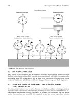
Use optical micrometer
to measure the offset at
this target
Step 1
Step 2
Step 3
Adjust tangent
screws to zero on
this target
Near to far target distance
Near target to
transit distance
Translation distance needed for correction =
(Near to far target distance
+ near target to transit distance)
*
(offset at near target)
Near to far target distance
New position
Original position
Translate the jig
transit to here
Translation distance
needed for correction
Offset at near target
Rotate the jig transit to
aim at the center of the
far target then focus back
to see if the near target
is also centered
FIGURE 19.21 Bucking in your line of sight to the centerline of the bore of the cylinder.
Piotrowski / Shaft Alignment Handbook, Third Edition DK4322_C019 Final Proof page 631 26.9.2006 8:43pm
Bore Alignment 631
OK, so much for dumb luck. The near and far targets are not directly in line with each
other. What you have to do now is translate the entire jig transit in the sideways
direction and rotate the jig transit through its azimuth (Z) axis to align the vertical
crosshairs of the telescope with the vertical paired lines on the near target. Similarly, you
have to raise or lower the jig transit in the vertical direction using the precision lift
mechanism and plunge (i.e., pitch) the jig transit through its pivoting (X) axis to align the
vertical crosshairs of the telescope with the horizontal paired lines on the near target. Now
there are two ways to do this: trial and error and mathematics. Both work, mathematics
just happens to be slightly faster but requires a little bit of number crunching.
Plug the scale target reading at the near target and the distances into the formula to
obtain the necessary translation distances.
2. Translate (i.e., move) the entire jig transit in the sideways direction to the amount you
calculated in the equation. You can either use the rotary indicator wheel on the
translation table where the scope is mounted or you can focus the scope on the near
target, set the optical micrometer to the desired lateral translation distance (assuming it
is under 100 mils), and begin translating the scope until the crosshairs line up on the near
target’s horizontal and vertical paired lines.
Raise (or lower) the entire jig transit in the vertical direction the amount you
calculated in the equation by adjusting the vertical lift mechanism. You can focus the
28 mils to the right
18 mils high
34 mils to the left
52 mils high
Telescope crosshairs are
bucked into the bore
centerline of the near
cylinder when these
measurement were taken
Near target in
far cylinder
Far target in
far cylinder
FIGURE 19.22 Measuring the amount of misalignment of the near and far targets in the far cylinder.
Piotrowski / Shaft Alignment Handbook, Third Edition DK4322_C019 Final Proof page 632 26.9.2006 8:43pm
632 Shaft Alignment Handbook, Third Edition
Scale :
10 in.
10 mils
Near cylinder
Far cylinder-far support
Far cylinder
Bore target position
Bolting plane
52 mils high
18 mils high
Far cylinder-far target
Far cylinder-near target
Far cylinder-near support
Near cylinder-near support
Near cylinder-far support
Side view
Up
Overlay/final desired alignment line
raise up 6 mils
Raise up 14 mils
FIGURE 19.23
Side view alignment model with one possible alignment solution
shown.
Piotrowski / Shaft Alignment Handbook, Third Edition DK4322_C019 Final Proof page 633 26.9.2006 8:43pm
Bore Alignment 633
Scale:
10 in.
10 mils
Near cylinder
Far cylinder-far support
Far cylinder
Bore target position
Bolting plane
34 mils to the left
28 mils to the right
Far cylinder-far target
Far cylinder-near target
Far cylinder-near support
Near cylinder-near support
Near cylinder-far support
Top view
Right
Overlay / final desired alignment line
Move 22 mils left
Move 14 mils left
Move 15 mils right
Move 23 mils left
FIGURE 19.24
Top view alignment model with one possible alignment solution
shown.
Piotrowski / Shaft Alignment Handbook, Third Edition DK4322_C019 Final Proof page 634 26.9.2006 8:43pm
634 Shaft Alignment Handbook, Third Edition
scope on the near target, set the optical micrometer to the desired vertical translation
distance (assuming it is under 100 mils), and begin translating the scope until the
crosshairs line up on the near target’s horizontal and vertical paired lines.
3. Once you have translated the scope you must now rotate the scope through its azimuth
axis so your vertical crosshair lines back up with the vertical paired lines on the near
target. Similarly, you now must plunge or pitch the scope through its X-axis so your
horizontal crosshair lines up with the horizontal paired lines on the near target.
If everything works well, the telescope’s line of sight should be centered at the near and far
targets. If not, repeat step 1 through step 3 until the telescope crosshairs and the centers of
both targets are in line with each other. At this point, the line of sight of the pivoting scope on
the jig transit is parallel to the bore centerline of the cylinder.
19.6 CORRECTING THE MISALIGNMENT
Once the bore targets were centered in the far cylinder and the telescope’s line of sight was
bucked back into the centerline of the bore of the near cylinder, measurements were taken at
the near and far targets of the far cylinder. To help visualize the misalignment between the
two cylinders and assist in correcting the misalignment condition, construct side view and top
view alignment models.
As shown in Figure 19.22, assume that the following measurements were taken at the far
cylinder targets:
Near target: 18 mils high and 28 mils to the right
Far target: 52 mils high and 34 mils to the left
Figure 19.23 shows an exaggerated misalignment condition between the near and far cylinders
in the side view (up or down direction). Figure 19.24 shows an exaggerated misalignment
condition between the near and far cylinders in the top view (left or right direction). Notice that
the target positions and bolting plane positions have been accurately scaled on the graph paper
from left to right and the bore centerline of the far cylinder has been accurately scaled from top to
bottom on the graph (see scale factors in lower left hand corner). Now a straight line can be drawn
on top of the graph and the cylinders can be moved to that overlay or final desired alignment line.
19.7 LASER BORE ALIGNMENT SYSTEMS
Laser–detector systems as shown in Figure 19.25 through Figure 19.30 have been developed
to accomplish the task of bore alignment. If you have not already done so, you might want to
review the information on lasers and photodiode detectors in Chapter 6 to get a basic
understanding of how these components work.
The principles of bore alignment with laser–detector systems are virtually identical to the
process using optical alignment equipment explained in this chapter. The laser beam is substi-
tuted for the visual line of sight established with a jig transit. Rather than visually observing a
sighting target placed in the center of a hollow cylinder, a photodiode is centered in the
cylinder and a cable transmits the position of the laser beam on the surface of the detector.
Piotrowski / Shaft Alignment Handbook, Third Edition DK4322_C019 Final Proof page 635 26.9.2006 8:43pm
Bore Alignment 635
FIGURE 19.25 D630 Extruder system. (Courtesy of Damalini, Molndal, Sweden. With permission.)
FIGURE 19.26 D630 Linebore system. (Courtesy of Damalini, Molndal, Sweden. With permission.)
Piotrowski / Shaft Alignment Handbook, Third Edition DK4322_C019 Final Proof page 636 26.9.2006 8:43pm
636 Shaft Alignment Handbook, Third Edition
FIGURE 19.27 Fixturlaser Extruder system. (Courtesy of Fixturlaser, Molndal, Sweden. With permission.)
FIGURE 19.28 Fixturlaser Centering system. (Courtesy of Fixturlaser, Molndal, Sweden. With
permission.)
Piotrowski / Shaft Alignment Handbook, Third Edition DK4322_C019 Final Proof page 637 26.9.2006 8:43pm
Bore Alignment 637
FIGURE 19.29 Pru
¨
ftechnik Boralign system. (Courtesy of Pruftechnik, Ismaning, Germany. With
permission.)
FIGURE 19.30 Pru
¨
ftechnik Centralign system. (Courtesy of Pruftechnik, Ismaning, Germany. With
permission.)
Piotrowski / Shaft Alignment Handbook, Third Edition DK4322_C019 Final Proof page 638 26.9.2006 8:43pm
638 Shaft Alignment Handbook, Third Edition
20
Parallel Alignment
Chapter 18 covered alignment of V-belt-driven equipment. As you observed, the goal of
aligning belts and sheaves is to get the driver shaft parallel to the driven shaft and the belts to
track straight in the sheaves. To accomplish this task, the outer surfaces of the sheaves or the
grooves of the sheave itself were used as the reference positions. The assumption is that the
outer surfaces of the sheaves or the grooves of the sheave itself are perfectly perpendicular to
its centerline of rotation. To verify the perpendicularity of the sheave to its shaft, face runout
measurements are taken as shown in Figure 18.13 and Figure 18.15. Once we are sure that the
sheaves are indeed perpendicular to their centerlines of rotation, we can then use straight
edges, strings, wires, or laser beams to align the sheaves, bringing the two shafts into a parallel
position. It seems cumbersome to use the sheaves as the reference positions but the shafts are
typically buried inside the machine casings, making it virtually impossible to use the shafts
themselves to measure from. If only the whole length of both shafts were exposed! Well, in
some cases, they are.
There are drive systems in industry that encompass a series of cylinders, shafts, or rolls
where they must be positioned so they are parallel to each other. Examples of this are
frequently found in the paper, plastic, printing, and steel industry.
20.1 ROUGH ALIGNMENT OF PARALLEL ROLLS
As a quick review, Figure 20.1 shows the coordinate system and terminology used in aligning
cylinders or rolls. The goal in aligning rolls is to get all rolls so that their individual y–z planes
are parallel or coplanar and their x–z planes are parallel or coplanar.
Perhaps the simplest method of measuring roll parallelism is to use a standard tape
measure. Effectively you wrap the tape measure around each roll, once at one end, record
the distance around and between the two rolls there, then again at the other end as shown in
Figure 20.2 and Figure 20.3. Compare the distance at the near and far ends. If the measure-
ments are the same, assuming both rolls are level with respect to gravity, the centerlines of
rotation of the rolls are parallel to each other.
If however, the rolls are not level with respect to gravity, their y–z planes may be parallel,
but the centerlines of rotation may not be parallel. Figure 20.4 shows how the two tape
measurement distances at the near and far end can be the same but the centerlines of rotation
of the rolls might not be parallel.
Bear in mind that the x–z plane does not have to be referenced to gravity, that is, the x–z
plane does not necessarily have to be level. Remember, level and aligned do not mean the
same thing. It is nice and convenient that the rolls are level but they do not have to be. If their
slopes are the same (i.e., the x–z plane is not level, but at a fixed angle), placing the rolls
parallel to each other is still achievable.
Piotrowski / Shaft Alignment Handbook, Third Edition DK4322_C020 Final Proof page 639 27.9.2006 1:30am
639
z
y
x
Roll
Pitch
Yaw
x
z
y
x
y−z plane
x−z plane
x
FIGURE 20.1 Coordinate system for cylinders.
Measure distance at near end
FIGURE 20.2 Using a standard tape to measure the distance between the rolls at the near end.
Measure distance at far end
FIGURE 20.3 Using a standard tape to measure the distance between the rolls at the far end.
Piotrowski / Shaft Alignment Handbook, Third Edition DK4322_C020 Final Proof page 640 27.9.2006 1:30am
640 Shaft Alignment Handbook, Third Edition
20.2 USING OPTICAL ALIGNMENT EQUIPMENT FOR ROLL PARALLELISM
The extreme accuracy and versatility of optical alignment equipment makes it ideal for use in
accurately positioning rolls for parallelism and perpendicularity. To align the rolls in
the vertical, horizontal, and if necessary the axial direction, two instruments are needed,
two telescopic transit squares or one telescopic transit square and a jig transit as shown in
Figure 20.5 and Figure 20.6. The transit square has a second scope affixed to the yokes of the
transit that is at a precise 908 angle to the main sighting scope.
20.3 ALIGNING THE ROLLS IN THE VERTICAL (UP=DOWN) DIRECTION
For this procedure you either need the telescopic transit square or a jig transit, a stand, and a
lateral translation slide.
1. Setup the optical transit on its tripod or base so that your line of sight is slightly above
the one of the shafts (or rolls). In this case, we set the equipment up to first observe the
position of the upper shaft (or roll) as shown in Figure 20.7.
2. Level the scope. Take a reading at scale target A and record the measurement. Take a
reading at scale target B and record the measurement. Measure the distance between the
scale targets and their respective positions to the bearings that support both ends of the
upper shaft (or roll). If the diameter of the roll is the same at both measurement
positions, and the readings at A and B are exactly the same, then the roll is level with
respect to gravity. If the diameter of the roll is the same at both measurement positions,
and the readings at A and B are not the same, then the roll has a slope with respect to
gravity. Determine what the slope is by obtaining the difference between the measure-
ments at A and B and divide it by the distance between target A and target B. This will
tell you the slope in mils=inch (or mils=foot if you prefer).
3. Move the optical equipment so you can sight along the top of the lower shaft (or roll)
as shown in Figure 20.8. Level the scope. Take a reading at scale target C and record
the measurement. Take a reading at scale target D and record the measurement.
Again, measure the distance between these scale targets and their respective positions
to the bearings that support both ends of the lower shaft (or roll). It is convenient,
but not necessary that the distance between scale targets A and B is the same as the
distance between scale targets C and D. If the diameter of the roll is the same at both
measurement positions, and the readings at C and D are exactly the same, then the roll is
level with respect to gravity. If they are not the same, determine the slope as described
in step 2.
Side view
End view
FIGURE 20.4 Centerlines of rotation are parallel in the y–z plane but skewed in the x–z plane.
Piotrowski / Shaft Alignment Handbook, Third Edition DK4322_C020 Final Proof page 641 27.9.2006 1:30am
Parallel Alignment 641
4. By comparing the difference between the readings you observed at scale targets A and B
and the difference between the readings you observed at scale targets C and D, you will
be able to determine if the rolls are parallel to each other in the up–down direction.
20.4 ALIGNING THE ROLLS IN THE LATERAL (SIDE TO SIDE) DIRECTION
For this procedure you need either a telescopic transit square and a jig transit or two
telescopic transit squares, a stand with lateral translation slides for each instrument, and a
light source for one transit.
1. The best way to perform this procedure is to use two telescopic transit squares or one
telescopic transit square and a jig transit. Setup the telescopic transit square on its stand
so that your line of sight is slightly to one side of one of the shafts (or roll) as shown in
Figure 20.9. This transit will be referred to as the measurement transit.
FIGURE 20.5 Telescopic transit square. (Courtesy of Brunson Instruments Co., Kansas City, MO.
With permission.)
Piotrowski / Shaft Alignment Handbook, Third Edition DK4322_C020 Final Proof page 642 27.9.2006 1:30am
642 Shaft Alignment Handbook, Third Edition
2. Level the telescopic transit square. Position scale targets on the side of the shaft (or roll)
at both ends as shown in Figure 20.9. Measure the distance between the scale targets and
their respective positions to the bearings that support both ends of the lower roll. You
should also measure the distance from the nearest scale target to the center of the
universal transit square (i.e., where it rotates through its azimuth axis). Loosen
the locking screw that will allow the pivoting telescope to rotate through the X axis.
What you are going to do now is position the universal transit square so the pivot-
ing telescope’s line of sight is parallel to the shaft (or roll) as shown in Figure 20.10
and Figure 20.11.
FIGURE 20.6 Jig transit. (Courtesy of Brunson Instruments Co., Kansas City, MO. With permission.)
Piotrowski / Shaft Alignment Handbook, Third Edition DK4322_C020 Final Proof page 643 27.9.2006 1:30am
Parallel Alignment 643
3. Take a reading at scale target E and record the measurement. Take a reading at scale
target F and record the measurement. If you are really lucky, the readings at scale targets
E and F are exactly the same (i.e., the telescope’s line of sight is parallel to the roll).
4. OK, so much for dumb luck. The readings at scales E and F are not the same. What you
have to do now is translate the entire universal transit square in the X direction and
rotate the universal transit square through its azimuth (Y) axis so the pivoting telescopes
line of sight is parallel to the lower shaft (or roll). Now there are two ways to do this,
trial and error or mathematics. Both will work, but mathematics just happens to be
slightly faster and requires a little bit of number crunching.
Optical jig
transit or
universal
transit square
Line of sight
Optical
scale
target B
Optical
scale
target A
Lower shaft
(or roll)
Upper shaft
(or roll)
Y
Z
X
FIGURE 20.7 Observing the vertical position of the upper roll.
Optical
scale
target D
Optical
scale
target C
Lower shaft
(or roll)
Upper shaft
(or roll)
Line of sight
Optical jig
transit or
universal
transit square
FIGURE 20.8 Observing the vertical position of the lower roll.
Piotrowski / Shaft Alignment Handbook, Third Edition DK4322_C020 Final Proof page 644 27.9.2006 1:30am
644 Shaft Alignment Handbook, Third Edition