Illustrated Sourcebook of Mechanical Components Part 6 pps
Bạn đang xem bản rút gọn của tài liệu. Xem và tải ngay bản đầy đủ của tài liệu tại đây (4.15 MB, 47 trang )
Washers
11-7
Tube crimped
Gefol
/lot
wosher
of
end
Rubber
flof
woshersv
-
VOCUl
-
Rubber
Ball
f/of
wusher ‘Adhesive bond
‘Adhesive bond
‘Ploslic chamber
4
Compression ball seat
5
Hose
bib retainer
,
Connec
fion
8
Protective bumper
9
Expansion isolator
11-8
Take Another
Look
at
Serrated- Washers
They're
a
stock item and come in a variety
of
sizes.
With a little thought they can
do
a variety
of
iobs.
Here are just eight.
Robert
0.
Parrnley
Washers
11-9
11-10
Dished Washers
Get
Busy
Robert
0.
Parmley
A
0
HEIGHT ADJUSTMENT
Jam
nuf
Dished
washer3
1
20
GUIDE WHEEL
Add rubber
befwsen
wosbers
for
gr@power
To
remove
pi??
Refahing
ring
I
COIL
SPRING STABlLlZEA
10
SIMPLE VALVE
Washers
11-1
1
Let these ideas spur your own design creativity. Sometimes commercial
Belleville washers will suit; other wise you can easily
dish
your own.
Washers
Section
A-A
Workpiece
Section
A-A
Base
3
ALIGNING BUTTONS
0
will rotate
if
holding screw is shouldered
here for
non-slipp;ng
non-s//p
arrangement/
4,
V-BELT
PULLEY
Rubber
sur
face adhesive.
A
Alternate: Profecf corners and
,Lock washer
I
I
tope
on
bevels
Sbc
Washers
/
7ff
I
7111
I
c
7.
END AND
CORNER
PROTECTION
11
FLARED SPOOL-FLANGES
Sho
f
fs
Beflevil/e
sprjng
washers Enlarged
\I
Jam
ffufs
/
Work area
12
0
CORRUGATING ROLLERS
FOR
PAPER
OR
CARDBOARD
11-12
Design
Problems
Solved
with
Belleville
Spring
Washers
Robert
0.
Parmley
Pulley assembly
Mounting spring stabilizer
(Nut and washer
Force
Retain tapered
coil
spring
Knurled adjustment
Washers
11-13
~elleviIle springs are a versatile component that offer a wide range
of
applications.
There are many places where these components can be used and their availability
as a stock item should be considered when confronted
with
a design problem that
requires a fast solution.
Secure anchor
bolt
Clamp fixture spring
,
Belleville
._
r
Lock retainer
Lock
mechanism
Machine
leg spring mounts
I
spring
disc
A
€5
C
11-14
HOW
to
Increase Energy
Capacity
of
Belleville,Spring Washers
New equations give stress-energy relationships and lead to the unusual arrangement
of
nesting Bellevilles one inside the other.
H.
P.
Swieskowski
INCE
1867,
when Mien
F.
Belfeville was issued a
S
patent in Paris for the invention, Belleville springs
have never ceased
to
find wide application. Now, more
and more, they are being used to absorb high impact
energies. With the arrangements and new design
equations given here, you can easily design
for
maximum
energy-absorbing capacity.
Also
called
conical
disk
springs, Belleville springs are
actually
no
more than conical washers. They are very
compact, which leads to first
of
several advantages:
@They can absorb
a
large amount
of
energy at high
loads and with a comparatively short working stroke.
They can return to the system practically all the energy
they absorb during the compression
or
impact stroke.
With ring springs, in contrast, approximately
50%
of
the input energy is dissipated as heat.
Their load-deflection characteristics can be altered
simply by adding
or
removing individual washers, by
stacking washers in various parallel-series combinations,
1
.
.
Four arrangements
of
Belleville
springs. The nested design
and by nesting them inside larger washers, Fig
1.
Generally speaking, Belleville springs are better suited
than helical compression springs where longitudinal
space is limited, in other words, where space for
solid
height is limited and where
a
helical spring would result
in a small index (the ratio
of
the mean coil diameter to
the wire diameter).
Design
recommendations
You
don’t need a maze of nomographs and tables
to
calculate the impact load
a
Belleville spring must absorb.
With these new design equations, given below,
you
can
predict the amount
of
induced stress directly.
But
first,
some important findings:
Nested springs-ne washer inside another-require
no more space than single springs and reduce the maxi-
mum stress by
14%.
One-parallel-series arrangements
of
Belleville springs are
more efficient energy absorbers than two-
or
three-parallel
TWO-PARAiLEL SERIES
THREE-PARALLEL
SERlES
has highest efficiency
for
absorbing
energy. Contrary to popular opinion,
the one-parallel design
is
more
efficient
than the two-
or
three-parallcl designs
Washers
11-15
series
-
contrary to some popular misconceptions.
0
Final working stress is directly proportional to the
square root
of
the energy capacity and inversely propor-
tional
to
the outside diameter and square root
of
the
solid height.
Oneparallel-series
equations
To
simplify analysis, it is assumed that the minimum
working height
is
equal
to
the solid height and that there
is no precompression
for
assembly. Thus the total deflec-
tion
is
Fs
=
HF
-
Hs
For
symbols, see
Box
on page
93.
The height-thickness ratio,
B
=
h/t,
determines the
shape
of
the load-deflection curve. By varying the
B
values, it is possible
to
obtain
a
wide variety
of
load-
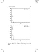
deflection curves, Fig
2.
The curves are plotted against the
deflection in terms
of
height as the spring washers are com-
NESTED
ARRANGEMENT
I
for
most ratios
of
dish height (deflec-
tion
to
flat)
to
metal
thickness.
Bel!eville
springs
.Preload
nut
Buffer
mechanism
with
Belleville
springs
for
high-impact energy absorption.
11-16
pressed from free height to solid height.
ville springs are
Load
The conventional
load
and stress formulas for Belle-
where the constants
C,,
C,
and
Y
are given by the equa-
t;ons
2.c
1
.E
l.E
1.4
1.2
a"
1.c
2
0
D
3
0.E
c
U
0
Of
01
0;
(
3
(A
-
1)
Ga
=
T
In
A
The constants can be iuickly approximated by means
of
Fig
3.
The stress equation, Eq
2,
givcs the value
of
the com-
pressive stress which occurs on the convex side at the
inner diamzter. The stress h2s
a
maximum value when
fi
=
h.
Hen-e the maximum (final) stress from
Eq 2
is
The energy stored in one washer compresszd
from
0
2h
0
4h
0
6h
Deflection
in
terms
of
height,
h
0.8h
h
2
.
.
LOAQ-DEFLECTION
CURVES.
The
hcight-thicknebs ratio,
S,
dclci-iniiics thc
shape
of
tl~c
CUI'VC.
Washers
11-17
free height to the flat position is obtained by integration
of
Eq
1:
-
For
an assembly of
N
washers in series
Keeping in mind that
H,
=
Nt
and
B
=
h/t,
Eq
5
is rewritten to read
EHs
t4B2
(B2
+
4)
Z(l
-
Q')
YD,'
EN
=
(6)
Combining
Eq
3
and
6
gives the relationship between
final stress and energy capacity:
For the usual spring materials where
E
=
30
X
loR
psi and
Q
=
0.3,
the final stress is
For all practical purposes, the stress at solid height,
which
is
the final stress, can be chosen at the permissible
stress-the maximum working stress for the spring.
text
continued,
page
94
Ra
tto
of
OD/
ID
3
. .
CONSTANTS
for
load
and
stress
equations.
SYMBOLS
General
symbols
A
B
c
values
of
C,
and
C,
Di
=
Inside diameter,
in.
Do
=
Outside diameter,
in.
E
=
Modu-us
of
elasticity, psi
EX
=
Energy capacity, in lb
F
=
Deflection, in.
FS
=
Total deflection,
in.
(FS=HF HX)
h
=
Dish height,
in.
HF
=
Free height
of
spring assembly, in.
HS
=
Solid height
of
spring assembly,
in.
P
=
Load, Ib
=
Poisson's ratio
=
Stress, psi
Q
s
ss
=
Final stress, psi
t
=
Thickness
of
washer,
in.
Y
=
Constant, see equation
or
chart
for
For one-parallel series
S'S
=
Diameter ratio
(A
=
D,,/D,
)
=
Height-thickness ratio
(B
=h/t)
=
Constant; see equations
or
chart for
(HsxNt)
values
Variation index
of
final stress
Energy capacity and final stress
of
in-
ner spring
in
nested design, in lb, psi
Energy capacity and final stress
of
outer spring in nested design, in.Jb,
psi
=
Number
of
washers
in
one-parallel
series
E.<,s:
N
For two-parallel series
B,
=
Height-thickness ratio
S"1
=
Final stress, psi
N?
For three-parallel
szries
B.3
=
Height-thickness ratio
SWd
=
Final stress, psi
N,
=
Number
of
parallel units each con-
taining two washers
=
Number of parallel units each con-
taining three washers
11-18
This is particularly true for critical applicalions where
spring space is limited and loading is
of
an impact nature.
In the design of Belleville springs,
a
main consideration
is to keep
the
final stress at a safe and reasonable level.
Eq
8
shows that the final stress is inversely proportional
to the outside diameter and the square root
of
the
solid
height; therefore, we make these two values as large as
space requirements allow. Doubling the value of the
outside diameter (keeping all other variables constant)
will result in
a
50%
reduction in the final stress.
A
similar increase in the solid height will produce a
30%
reduction. Eq
8
further shows that the final stress is
directly proportional
to
the square root
of
the energy
capacity.
The values
for
the outside diameter, solid height, and
energy capacity are usually given within narrow limits for
a particular application. The outside diameter is deter-
mined by the hole diameter into which the spring mud
fit. The value of the solid height
is
dictated by the
minimum working height and the energy capacity
is
pre-
scribed by functional considerations.
The question now remains, what ratios of
A
=
OD/
ID
and
B
=
h/t
will result in the minimum final stress?
Visual examination of Eq
8
does
not
readily show
the
stress effect of the two ratios.
However, by simplifying
Eq
8,
a series of design curves, Fig
4,
is obtained in
which the final stress factor is plotted wiah respect
to
ratio
A.
Ratio
B
acts as
a
parameter.
For this chart,
Eq
8
becomes
where
S’,
is called the variation index of the final stress.
It
can be seen from Fig
5
that
the
final stress
is
at
a
minimum when the diameter ratio
A
=
1.7 for
all
values
of
B.
Also,
for
a
given
B
value, the final stress increases
at most by
3%
in
bhe range
1.5
4
A
6
2.0.
Therefore,
we recommend that the diameter ratio should be kept
within the range
of
1.5
to
2.0.
Note also from Fig
4
that in the favorable diameter
ratio range the final stress increases with increasing values
of
B.
This condition is true except for the height-thickness
ratio of
B
=
3,
for
in
the range of
A
=
1.5
to
A
=
2.0, the final stress for
B
=
3
is
less
thm
that
for
smaller
B
values (of
1
<
B
L
2). Belleville washers,
however, have \been generally designed for energy
ca-
pacity with
B
values less
than
unity because frequently
a short work stroke and a high degree of stability are
required.
Example lane-parallel design
A
set of Belleville springs, grouped into
a
oneparallel
series arrangement, are to absorb the recoil
of
a rifle
bolt. The given requirements are:
Outside diameter,
Do
=
0.900
in.
Solid height,
H8
=
2.035
in.
Stroke,
F8
=
0.407
in.
Energy-absorption requirement,
EN
=
100 in lb
Material
=
alloy steel,
AIS1
6150
Step
1:
Select the diameter ratio.
Based on the pre-
vious recommendations, a ratio
of
A
=
OD/lD
=
1.7
is chosen. Therefore from Fig
3
(or,
for more accuracy,
from the equations of the constants)
:
C,
=
1.15,
C,
=
1.26,
Y
=
0.61
Step
2:
Determine the height-thickness ratio. In this
case a stroke of
0.407
is required, which means that
=
0.2
h
2
H,
2.035
B=
F8
-%!!!?
Step
3:
Calculate final working stress from
Eq
8:
=
222,000psi
Step
4:
Calculate the thickness,
t.
If
the stress value
of
222,000
psi is acceptable, the thickness
t
can now
be calculated from either Eq
3
or 6.
From Eq
3:
Ski,
5:
Dctcrminc
thc
dish height,
I?:
I&
=
B1
=
0.3(.055)
=
0.011
itb.
Step
6: Determine the number of washers:
The complete design data
for
this spring are listed
in the second column in Table
1.
The data will be com-
pared later
to
a
nested arrangement.
Variations
in
stroke
The analysis shows that increased spring travel can be
obtained with no corresponding increase in final stress.
16
15
14
-2:
1.3
x
D
2
12
c
rn
I
-
n
c
-
LL
1.1
1.c
G:
Ot
I
I
I
0
20
30 40
Dicrneter
ratio,
A:OD/ID
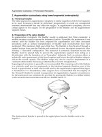
4
.
.
STRESSES
IN
one-parallel Bellevilles
Washers
11-19
Consider the point
A
=
2.0
and
S'#
=
1.07 in Fig
4.
The two curves
B
=
1
and
B
=
3
intersect at this point
which means that two spring designs can occupy the
same
spring
space
(in
other words, with the same
Ha
and
Do
values), end have equal energy capacities and final
stresses-however, their total travel,
FB,
will be in the
proportion
of
3
to
1.
To
illustrate this point, consider
the
two
springs listed
in
Table
I1
with the same values for:
Outside diameter,
Do
=
2.300 in.
Inside diameter,
Di
=
1.150
in.
Solid
height,
Hs
=
3.650 in.
Total
travel,
k's
6
3.000 in.
Energy requirement
=
342
in.
lb.
Material
AISI
6150
The two springs have been desigded
to
B
=
1
and
B
=
3.
Final stress and energy capacity
of
both designs
are equal, but the springs differ in total travel and
numfber of washers. The load-deflection diagram
for
each design is shown in Fig
5.
The energy capacities for
the springs are represented by the areas under the curves.
The areas are equal to each other. Note that there is an
energy content common to both designs. The total travel
for design
B
(4.95
in.)
is
three times that
of
design
A
(1.65
in.).
Nested arrangements
Again, to simplify the analysis, it is assumed that
there is no diametral clearance between the nested springs.
To
have
a
meaningful comparison, both assemblies are
designed to the same values for:
.Energy capacity,
EN
=
ENo
-t
EN' (where super-
TABLE
I
SINGLE
VS
NESTED ARRANGEMENTS
Thickness, in.
Dish height, in.
Number
of
washers
Diameter ratio
Outside diameter, in.
Inside diameter, in.
Height-thickness ratio
Stroke, in.
Solid height,
in.
Energy capacity,
in lb.
Material,
AIS1
Final stress, psi
scripts
o
and
i
purtain
to
the oulcr
and
inncr springs,
respectively.
.Stroke,
F8
Solid height,
Ha
Diameter ratio,
A
=
1.7
0
Material,
AISI
6150
Outside diameter (the outside diameter of nested
arrangement equals the outside diameter
of
single spring)
For
outer spring
For
inner spring
For efficient design,
the
stress in the nested arrange-
ment should be equally distributed,
thus
Sao
=
&'.
There-
fore
Eq
9
and
10
result in
EN'
=
2.89
.EN'
(11)
EN
=
1.346
ENo
(12)
From the basic assumption that
EN
=
ENo
+
EN',
and
from Eq
11,
it follows that
The relationship between the final stress of the single
springs to that of the nested spring
is
obtained
from
Eq
S,
9
and
12
as
(13)
Ss
=
1.168s"
Therefore, the percentage reduction in final stress,
AS,
ONE-PARALLEL
ARRANGEMENT
0.055
0.01
1
37
1.7
0.900
0.530
0.20
0.407
2.035
100
6150
222,000
NESTEO ARRANGEMENT
OUTER SPRING INNER SPRING
0.051
0.0102
40
1.7
0.900
0.530
0.20
0.408
2.040
74
6150
191,000
0.030
0.006
68
1.7
0.530
0.312
0.20
0.408
2.040
26
61
50
191,000
11
-20
that
is
gained by the substitution
of
a
nested arrange-
ment for
a
single spring
is
The stress reduction is constant and applies generally
because it is independent
of
the solid height and outside
diameter
of
the single spring.
I'xample >Nested design
Assume that the final stress
of
222,000 psi in the first
cxample
is
excessive and must be reduced. The use
of
a
riested arrangement will decrease the stress by
31,000
psi
to 191,000 psi.
A
nested arrangement that
is
equivalent
to the first spring in energy and space conditions is easily
computed with the aid
of
Eq
3
and
Eq
9 through
13.
The
design data are listed
in Table
I.
The solid height and total stroke
of
the nested design
are not exactly equal
to
those
of
the single spring because
the number
of
washers in each spring has to be a whole
number. However, their differences are negligible, and
for comparison purposes the height and stroke are con-
sidered equal. Note that the individual energy capacities
total 100 in lb in Table
1.
Other parallel-series arrangements
A
comparison is now made
of
a one-parallel series
with two-parallel and three-parallel series. Again, for a
vlilid comparison, all spring assemblies have the same
300
n
-
20c
T3
0
0
-I
IOC
values for energy capacity, stroke, solid height, diameter
ratio, material,
and
outside diameter.
For two spring washers in parallel, the load-deflection
formula
is
=
+l-Q2)YDa[(
4EF
h
-
-
:)
(h-P)
t+t3
]I
(1A)
The energy stored in the washers upon compression
,from free to solid height
is
The energy stored in
,a
two-parallel series, as shown
in
Fig
1,
with
N,
pairs
of
washers is
(5A)
With the equations
H,
=
2N,t
and
B.
=
h/t,
Eq
5A
is
transformed to
EH&Bz2
(B2'
+
4)
2(1
-
Q')
Y
Doz
Eiv
=
Stress at solid height of the two-parallel series
is
L
(OA)
I
/-Spring
A
Spring B
/
I
1
10
1.65
2.0
3.0
Deflection,
in
I
4.95
5
.
.
COMPARISON
OF
ENERGY CAPACITY.
Both
springs can absorb equal amounts for
a
given
stress level. Spring
A,
however, accomplishes
the
job
in one-third the distance required for spring
B.
Combining
Eq
3A
and
6A
gives the following expres-
sion for the two-parallel series:
(I
-Q2)
2E
Hs
Ex
(Rz2f4)
Y
)"[
c,
2
+
C2]
(7A)
The relationship
of
the final stress of the one-parallel
series to
the final strew
of
two-parallel series, obtained
from
Eq
7 and
7A,
is
From the given condition that both assemblies should
have equal strokes, it follows that
Bg
=
2R
(15)
Therefore,
Eq
14
is
rewritten as
L
A graph
of
the stress ratios for one and two-parallel
series arrangements are shown in Fig
7.
Note that in
the practical range
-of
B,
(B
1),
the one-parallel series
is
more efficient &an the two-parallel series. This
is
particularly true for
B
values between
0.3
and
0.6
where
ail
8%
stress savings can be realized.
Washers
TABLE
11.
.SAME PERFORMANCE
-
DIFFERENT TRAVEL
I
SPRING
A
I
Outside diameter,
in.
2.300
Inside diameter, in.
~
1.150
Height, in.
~
0.055
Thickness, in.
1
0.055
i
Height-thickness ratio 1
.o
Diameter ratio
Number
of
washers 30
Solid height, in. 1.65
Total travel, in. 1.65
I
Final stress,
psi
21
8,000
Energy capacity, in lb.
1
342
Material,
AIS1
i
6150
SPRING
B
2.300
1.1 50
0.075
0.025
3.0
2.0
66
I
.65
4.95
21
8,000
342
61 50
11-21
11
-22
Similarly, the ha1 stress of the three-parallel series
(shown
in
Fig
1)
is
In combination with Eq
7,
and the
fact
that both
assemblies have equal strokes, it follows that the ratio
of stresses of one-parallel to three-parallel design is
L-
This equation is
also
plotted in Fig
6.
Note that in
the practical
B
range, the one-parallel series offers a
better utilization
of
spring space than a three-parallel
series. For example, two spring assemblies that corre-
spond to the points
B
=
0.4
and
Ss/S,
=
0.87
(a one-
parallel series, with
B
=
0.4,
and a three-parallel series,
with
B,
=
1.2) will have equal strokes and energy ca-
pacities and occupy the same space package. The final
stress
of
the one-parallel series, however, will be
13%
less. This comparison is shown in Table
III.
Ged
load-deflection
formulas
load-deflection
(P/F)
calculations are
Formulas that can be used to good advantage for
P
-
4Et3
_-
F
(1-&2)
D2YN
and
(20)
4Et4
-
P
_-
F
(1-Q')D)
For the usual spring materials where
E
=
30
X
10"
psi and
Q
=
0.3,
the above equations are reduced
to
P 132
X
106ta
F
Do2
YN
-=
and
P
132
X
106t4
-=
F
D2
YHs
(19A)
The formulas are more convenient
to
use
than
Eq 1
and are acceptably 'accurate for
B
values less than
dr
equal to unity, where the rate is essentially linear, as
can be seen from Fig 2.
Other
design recommendations
To
simplify the analysis, it was assumed that there
was
no
initial spring compression and also that there was
no clearance between minimum operating height
and
solid height. However, in actual practice, it is recom-
mended that a small precampression be applied to pre-
vent looseness and that clearance be provided to avoid
loading to flat position. The two recommendations are
easily satisfied by designing for a total energy capacity
slightly larger than actually required.
Stress values given by Eq
2
and
8
are localized stresses
that
occur
at the inner diameter and not throughout the
entire cross section. Therefore, caloulated stress values
may at times exceed the yield point
of
the spring mate-
rial and yet be permissible.
TABLE
111
ONE-PARALLEL
VS
THREE-PARALLEL ARRANGEMENTS
Number
of
individual washers
Outside diameter, in.
Inside diameter, in.
Diameter ratio,
Height
Thickness, in.
Height-thickness ratio,
Stroke, in.
Solid height, in.
Energy capacity, in lb
Final stress, psi
ONE-PARALLEL
SERIES
26
1.87
1.10
1.7
0.034
0.085
0.4
0.884
2.21
600
305,000
THREE-PARALLEL
SERIES
48
1.87
1.10
1.7
0.055
0.046
1.2
0.884
2.21
600
266.000
Washers
11
-23
SEM
Applications
N.
Dale
tong
when a split lockwasher is called
for
in a screw fastening,
a flat washer
is
invariably necessary. The ways
of
assembling
them illustrated below are strict requirements in military
specifications-especially for electronic equipment.
Corn-
shown here
can
be depended
on
to
pay
off.
mercial requirements usually vary-depending upon either
the designer’s decision
or
product-cost restrictions.
For
good
quality and reliable service, however, the fastening methods
ASSEMBLY
OF
FLAT WASHERS AND
SPLIT
LOCKWASHERS
Flut
washers
should
be
placed
between .
.
.
Nome
fa/
maieriol
/F/oi
washer
F/ai
washer
Meid
Q032-ik
or
less
ihkk
F/a
f
washer
-
washer
11
-24
Creative
Ideas
for Cupped Washers
A
standard off-the-shelf item with more uses than many ever considered.
Robert
0.
Parmley
2
Simple step pulley
sher
(sectioned]
m
y’’’’A
b
Tubing connector
Cupped washer
)
(press
fit
or
weld)
€nd
3
Rod aligner and pipe-end bearing
Cupped
washer
7
Simple piston
for
cylinder‘
Washers
11
-25
1
Coil
spring stabilizer and compression brake
Cupped washers
Cupped washers
h
‘snap
rings
Snop’ring
4
Simple
pulley and roller
IV
I
I.
1
Cupped
washer)’
8
Toggle
switch
housing
Inverted
Post
shoe
5
Post
anchors and supports
CURRed washers
[sectioned
Plostic
stem
9
Protection
for
step shoulders
I
L
LU
S
T
RAT
E
D
S
OU
RC
E
B
0 0
K
of
ME
C
HAN
I
CAL
C
0
MP
0
N
E
N
T
S
SECTION
12
RETAINING
Comparisons of Retaining Rings Verses Typical Fasteners
12-2
12-4
12-6
12-8
Retaining Rings Aid Assembly,
I
Retaining Rings Aid Assembly,
II
Coupling Shafts with Retaining Rings
The Versatile Retaining Ring
12-12
The Multiple-Purpose Retaining Ring
12-16
More Work for Round Retaining Rings
12-18
12-20
12-22
12-24
Energy Absorber Squeezes Rings to Cushion Shocks
Defection of Perpendicularly Loaded
Split
Circular Rings
Improve Design with Retaining Rings
RETAIN COMPONENTS
on diecastings with
a simple-to-use grip ring. Slipped over the
end
of
the shaft, the ring exerts a frictional
hold against axial displacement
of
the shaft.
r i
Retaining Rings
12-3
7
SHOULDER AND NUT
are replaced by
two
retaining rings.
A
flat ring replaces the shoul-
der, while a bowed ring holds the component
on shaft for resilient end-play take-up,
THREADED INTERNAL FASTENERS
are
costly because
of
expensive internal thread-
ing operation. Simplify by substituting
a
self-
locking retaining ring-see lower drawing.
COVER-PLATE ASSEMBLY
has been re-
designed (lower drawing) to avoid
use
of
screws and machined cover-plate.
Much
thin-
ner wall can be used-no drilling
or
tapping.
w
W
HEAT-FORMED STUD
provides
a
shoulder
against retained parts but must be scrapped
if
the parts must be disassembled for serv-
ice. Self-locking ring can be easily removed.
Free
ring
Groove
detail
Roller
Roller
axle
Heavy-duty
Two types of rings may be used on one assembly. Here permanent-shoulder rings
provide a uniform axle step for each roller, without spotwelding or the like.
Heavy-duty rings keep the rollers in place
Reinforced circular
self- locking
rapered
-section
self- locking
Retaining Rings
12-5
Reinforced
E-
ring
Bowed
locktnq-
prong
ring
Snug assembly
of
side members to
a casting with cored hole
is
secured
with
two
rings: 1-spring-like ring has
high thrust capacity, eliminates springs,
bow washers, etc; 2-reinforced E-ring
acts as a retaining shoulder or head.
Each ring can be dismantled with
a
screwdriver
~~il~~~~~~g
Triangular retaining nut eliminates the
need for tapping mounting holes and
using a large nut and washer. Secure
mounting
of
small motors and devices
can be obtained in this manner
These three examples show self-locking retaining rings used as adjustable
,stops on support members (pins made to commercial tolerances): A-external
riug provides positive grip, and arched rim adds strength; B-ring is
adjustable in both directions, but frictional resistance is considerable,
and C-triangular ring with dished body and three prongs will resist extreme
thrust. Both
A
and
C
have one-direction adjustment only
Retaining Rings
12-7
\.
/Housing
\
Ring
\
f
Vacuum
released
Internal self-locking ring supports the plastic ball valve
when the vacuum is released, thus providing a support
during the "off" cycle. Air or liquid is released when ball
is at rest and exits through the areas between the grip
points
of
the ring, which is adjustable at entry position
s+em m
Weight
disc,
I I
.
Ring
-Rubber stopper
with
internal
threaded
sleeve
Drain
hole
Triangular retainer
nut
positions and unifies components of
the tank drain assembly. The triangular nut eliminates the
need
for
a large standard nut and lockwasher or spring-
type component and simplifies the design
Tamper-proof lock for a shaft
in
a
housing provides location of the
shaft and at the same time retains
the key. Heavy axial loading and
permanent retention of the key are
double values
in
this application
Ring
half\
Observation
lid
"I*
u
Ring half
Observation
lid
on tubing makes
it
possible to inspect wiring at will.
The two-part balanced retainer ring
has identical semicircular halves,
which are held together by the
interlocking prongs at the free ends
Retaining Rings
Shaft
half
Retaining ring
\
A
balanced two-part ring provides an attractive appearance in addition to with-
The one-piece ring,
b,
standing
high
rotational
speeds
and heavy thrust loads,
a.
secures the shafts in
a
high-torque capacity design.
12-9
This
assembly for heavy-duty service requires minimum machining.
Ring thickness
should
be substantial, and extra ring-section height
is
desirable.
12-
10
self-locking
ring
a
Shaft
VA
_____I
14
I
I I
I
r
For a connection that requires axial shaft adjustment, the self-locking ring requires
An alternate solution,
b,
uses an inverted-lug ring seated in an internal
The ring
is
uniformly
no groove, a.
groove.
concentric with housing and shaft.
Extra ring-section height provides a good shoulder.
Coupler
and
Coup1;ng
half
Retaining
ring
Ring groove
I
Couplings locked
to
shafts
r
with sei screw
and
keys
Where attractive appearance
is
desired in a dependable locking device, this
connector and ring can be used.