Illustrated Sourcebook of Mechanical Components Part 7 potx
Bạn đang xem bản rút gọn của tài liệu. Xem và tải ngay bản đầy đủ của tài liệu tại đây (3.81 MB, 44 trang )
Grommets, Spacers
&
Inserts
14-11
A
C
B
\
I
7
D
two general types. The first uses modified external threads
that form an interference with the parent material, and
provide locking action. The second type has many varia-
tions, but is characterized by standard external and in-
ternal threads, with various types
of
pins or keys to lock
the bushing to the parent material. Some of the most
widely used variations are:
A
two-piece insert with a locking ring and two keys
fits into mating grooves in upper external threads, The
ring is pressed into place after the insert is screwed into
tapped hole; it cuts through enough threads of parent
material to provide a positive lock.
A
counterbore in the
tapped hole is required for the ring, but assembly and
replacement can be made with standard tools.
Another solid bushing insert has
bo
integral keys
which act as
a
broaching tool when insert is installed
flush with the parent material. Locking pins are pressed
into the base
of
the tapped hole through the grooves in
the external thread.
Still another, a solid bushing, has standard internal and
external threads and an expandable upper collar with
serrations in the outer surface
to lock the insert in the
parent material.
Factors
that
affect selection
type:
These factors must be considered in selecting the best
Shear strength of parent material
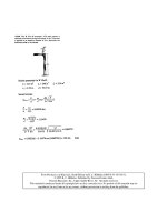
SOLID
INSERTS
FOR
PRE-
TAPPED
HOLES
have many
variations.
Among
the
most
pop-
ular are:
(A)
modified external
threads
for
interference
and
lock-
ing
action;
(B)
two-piece
unit
with
key
ring
for locking actfon;
(C)
integral
keys
give
locking
action:
(D)
expandable collar
with external wrrations.
Operating temperature
Load requirement
Vibratory loads
Assembly tooling-serviceability and ease
of
installation
Relative cost
Shear strength
of
parent material below
40,000
psi gen-
erally calls for threaded inserts. This includes most
of
the aluminum alloys, all magnesium alloys and plastic
materials. But other factors must
be
considered.
High operating temperature effects the shear strength
by reducing strength of the parent material; an insert with
a IaTger shear area may be required.
Bolt loading frequently makes it necessary to use
threaded inserts. For example, if the full pull-out strength
of
a
125,000-psi bolt is required, it is probable that the
parent material will need a threaded insert to increase the
shear area and thus reduce the effective shear stress.
Vibratory loads may reduce bolt preload, and require a
threaded insert to increase the effective shear area.
Or
vibration may cause creep, galling, and excessive wear, and
inserts with both external and internal thread-locking fea-
tures will be needed.
The pullout capacity
of
an insert is
a
function of pro-
jected shear area, and should equal the tensile strength
of
the bolt. This means pull-out strengrh should be greater
than torque-applied tensile strength of the bolt.
In wire thread inserts the projected shear area per coil
14-12
500
r
400
-
+
L
300
-
f
200
-
.t-
0
0
V
RELATIVE EVALUATION-5 TYPES
OF
THREAD INSERTS
!A-self-tapping insert; B-wire thread insert; C-solid bushing
for pre-tapped holes; D-solid bushings for pre-fapped holes
and
external interference threads; E-self-fapping insert)
0
400
-
4-
+
300
-
z
3-
a
+
C
E
O
2-
El
D
c
v)
Lo
v1
0
L)
D
-
al
m
0
w
0
8
200
-
c
A
E
-
100
E
I
0
COST
OF
PART
is
price quoted
for
TOOL COST
for
each
type is based on
lots
of
1000.
manufacturer’s prices
for
tooling
a
evaluation.
EASE
OF
ASSEMBLY
is
a
qualitative
standard tapping head.
0
;ii
Iiii
$4
23
.+
O2
=I
0
0
NUMBER
OF
ASSEMBLY
OPERA-
TIONS
covers
complete installation
of
an
insert, including drill, counterbore,
tap,
ream, install and reinspect.
d
n
)!I,
0.4
0.5
0.6
0:7
018
d19
1.0
Effective
Shear
Area,
sq
in.
A
USEFUL
RELATION
is effective shear area to
D/L
ratio.
It determines required insert length
or
pull-out strength.
Solid curves
are
for
self-tapping inserts; dotted curves for
wire thread inserts.
is relatively small; only way to increase the total projected
shear area is to increase the number of coils. On the
other hand, in solid and self-tapping inserts the projected
shear area Can be increased
by
a larger
OD
as well as
by
more threads, while maintaining the same bolt diameter.
One way to determine adequacy of pull-out capacity is
to
plot
the ratio of the internal diameter vs insert length
as a function of the effective shear area developed in the
parent matcrial. The accompanying curves for three sizes
of sclf-tapping and wire thread inserts were derived from
tats in which the insert was pulled out
of
the parent ma-
terial. Similar curves could be developed to determine the
length needcd for
any
othcr type of insert.
For
exnmplc, assume that
a
+-28
bolt with an ultimate
strength
of
5000 Ib is to bc uscd in a material with a
shear strength
of
20,000 psi. The required shear area
is 5000 lb/20,000 psi
=
0.25
sq
in. From the accom-
panying curves, the
D/L
ratio is
0.57;
insert length,
L
=
0.25/0.57
=
0.438
in.
Similar calculations, using the same curves, can deter-
mine whebher length
df
bhe insert is sufficient
to
give
a
required amount
of
creop resistance: The creop strength
of
the parent material is substituted for shear strength
in the above calculation.
Also,
if the inscrt lcngth is limited, these calculations
wiil give the availaMe pull-out strength, which will vary
wibh shear arca of the insert. This analysis can be used to
dctcniiine cithcr the rcquircd length or pull-out strengbh,
and from this, the thickness of the parcnt material for
minimum weight and maximum economy.
Solid threaded bushings oftcn permit using a shorter
bolt than for the wire thread insert with limited shear area.
Witth a large number of fasteners in an assembly, weight
saving in reduction
of
parent material is much greater
bhan the small extra weight added by the solid insert.
Other important factors in sdecting inserts are assem-
bly tooling, serviceability, relative cost, and ease of installa-
tion. These factors have bcen evaluated in the bar charts
prepared
by
W.
Moskowitz
of
GE’s
Missile and Space
Vehicle Dept, Philadelphia.
Dab
are for five types using
10-32
internal thrcads. Part of this information
is
based
on
estinwtcs
of
the operating pcrsonnel concerning the
numbcr
of
assembly
qcrations, tolerancus rcquired during
installation, and relative
ease
of
installation.
Grommets, Spacers
&
Inserts
14-13
Flanged Inserts Stabilize
Multi-Stroke Reloading Press
E. E.
Lawrence, Inventor
Robert
0.
Parmley, Draftsman
Flanged Insert
\
I
I
I
I
1
L
0
Flanged Insert
/
/
Flanged Insert
W
ILLUSTRATED SOURCEBOOK
of
MECHANICAL COMPONENTS
SECTION
15
12
Ways to put Balls to Work
15-2
15-4
Rubber Balls Find Many Jobs
15-6
Multiple Use of Balls in
Milk
Transfer System
15-8
Use of Balls in Reloading Press
15-10
Nine Types of Ball Slides for Linear Motion
15-12
Unusual Applications of Miniature Bearings
15-14
Roller Contact Bearing Mounting Units
15-16
Eleven Ways
to
Oil Lubricate Ball Bearings
15-18
Ball-Bearing Screw Life
15-20
Stress on a Bearing Ball
15-27
Compute Effects of Preloaded Bearings
15-29
Compact Ball Transfer Units
15-39
How
Soft
Balls Can Simplify Design
Balls
15-3
11
BALL-LOCI( FASTENS
STUD
IN BCIND
HBLE
.
Exponds
u8en hqnde
is
serewedon
shoft
*
*I
*1
3,
,
>>
",
ST-BEARjNG
TAKES
LIGHT
LOADS.
'
I
Balls
15-5
Balls
15-7
HOLLOW
SHAFT-SEAL
embodies
ad-
hesive-bonded rubber ball with flow hole.
Quick connection
of
leakproof
joint
for
7
lubricant
or
other
liquid
is
gained.
Balls
15-9
Balls
15-11
Balls
15-13
5
Sleeve bearing consisting
of
a hardened sleeve, balls and
retainer, can be used for reciprocating as well as
osdl-
lating motion. Trawl is limited similar to that
of
Fig.
6.
This
type can withstand transverse loads in any direction.
Ball reciprocating bearing
is
designed for rotating, re-
6
ciprocating or oscillating motion. Formed-wire retainer
holds balls
in
a helical path. Stroke is about equal to twice the
difference between outer sleeve and retainer length.
Ball bushing with several recircu-
7
lating systems
of
balls permit
un-
limited linear travel. Very compact,
this
bushing simply requires
a
bored
hole
for
installation. For maximum
load capacity a hardened
shaft
should
be used.
8
Cylindrical shafts can
be
held by
commercial ball bearings which
are assembled to make
a
guide. These
bearings must
be
held tightly against
shaft to prevent looseness.
Curvilinear motion
in
a
plane
is
9
possible with
this
device when
the radius
of
cumam
is
large. How-
ever, uniform spacing between grooves
is important. Circular
-
sectioned
grooves decrease contact stresses.
Hamilton
Standard
*
Bearing,
Fig.
5-PRECLSE
RADIAL.
ADJUSTMENTS
obtained by
dating
the
eccentric shaft thus
shifting
location
of
bearing.
Bearing
has
special-
contoured outer race
with
standard inner race.
Application is to adjust a lens with grids for
an aerial survey camera.
Thrust bearing,
Balls
I
Housing-
-
-
-
-+
Threaded
coffar
-
-
-
-
Stepped
-
r'
caffar
/
Fig.
74EAR-REDUCTION
UNIT.
Space
requirements reduced by having both input and
output shafts at same end of unit. Output shaft
is
a
cylinder with ring gears at each end. Cyl-
inder rides in miniature
ring
bearings that have
relative large inside diameters in comparison
to the outside diameter.
15-15
f-f
'Lens
Fig.
MUPPORT
FOR
CANTILEVERED
SHAFT obtained with combination
of
thrust
and flanged bearings. Stepped collar provides
seat for thrust bearing
on
the shaft but does not
interfere with stationary race of
thrust
bearing
when shaft is rotating.
Gear train Ring gear
I
I
I
I
,Ring
bearings
0
1
,'
Ouier bearing race-
-
y
Rubber tip
for
tachometer
readings
I
\
I
\\
I
Inner bearing race,
,/*h
Fig.
8-BEARINGS USED AS GEARS.
Manually operated tachometer must take
readings- up -to
6000
rpm. A 1040-1 speed
reduction was obtained by having two bear-
ings
function both as bearings and
as
a
planetary gear system. Input shaft rotates
the inner race
of
the inner bearings, causing
the output shaft to rotate at the peripheral
speed
of
the balls. Bearings are preioaded
to prevent slippage between races and balls.
Outer housing is held stationary. Pitch di-
ameters and ball sizes must be carefully
Bearing'
\\
calculated to get correct speed reduction.
Sfationory
housing
Balls
15-17
Fig. 5-me cylindrical car-
tridge is readily adaptable to
various types of machinery.
It
is fitted as a unit into a straight
bored housing with
a
push
fit.
A
shoulder
in
the housing is
desirable but not essential. The
advantages
of
a predesigned
and preassembled unit found in
pillow blocks also apply here.
FIG.
6-The flange mounting
unit
is
normally used when the
machine frame is perpendicular
to the shaft. The flange mount-
ing unit can be assembled with-
out performing the special bor-
ing operations required in the
case of the cartridge. The unit
is simply bolted into the hous-
ing
when
it
is being installed.
FIG.
7-The ftange cartridge
unit projects into the housing
and is bolted
in
place through
the flange. The projection into
the housing absorbs a large part
of the bearing loads.
A
further
use of the cylindrical surface is
the location of the mounting
unit relative to the housing.
U
(B)
FIG.
&Among
specialized types
of
mounting
units
are
(A)
Eccentrics used
particularly
for
cottonseed
oil
ma-
sible an adjustment
in
the
position
of
bearing mounting units are made.
chinery and mechanical shakers and
the
shaft for conveyor
units.
Many
(B)
Take-up
units
which
make
pos-
other types
of
special
rolling
contact
Balls
m
Fig.
7-Another
screw
bumb abblication
15-19
I
. .
forces the oil upward through an external
passage. The cup-shaped slinger traps
some oil as the spindle comes to rest.
Upon starting, this oil is thrown into the
bearings and avoids a short initial period
of
operation with dry bearings.
Fig.
&Most
circulating
systems
are used
tor
vertical shaft applications and usually
where ball speeds are comparatively high.
Dne system consists
of
an external screw
which pumps the oil upward through the
hollow spindle to a point above the top
>ear
i
n
g
s
.
Fig.
%-Wick
Feed
filters and transfers
oil
to
a smoothly finished and tapered rotating mem-
ber which sprays a mist into bearings.
Wick
should be in light contact with the slinger
or
Fig.
9-Wick
feeds
are used in
applications
of
extremely high
speeds with light loads and where
a very small quantity
of
oil
is
re-
quired in the form
of
a fine mist.
Slingers clamped on the outside
tend to draw the mist through the
Fig.
IO-Air-Oil
Mist.
Where the
speeds are quite high and the bear-
ing
loads relatively
light,
the
air-
oil
mist
system
has
proven
sue-
cessful
in
many
applications.
Very
little
oil
is
and
the
air
flow serves to cool bearings.
Fig.
Il Pressure let. For
high speeds
and heavy loads, the
oil
must often
function as a coolant. This method
utilizes a solid jet
of
cool oil which is
directed into the bearings. Here ade-
quare drainage is especially important.
The
oil
jets may be formed integrally
with the outer oreload saacer.
Balls
15-2
1
The basic unit
ot
a ball-bearing
screw assembly consists
of
a screw and
nut having helical races separated by
balls. A tubular guide on the nut in-
terrupts the path of the balls, deflects
them from the races, and guides them
diagonally across the outside of the
nut and back to the races. In opera-
tion, the rolling balls recirculate con-
tinuously through this closed circuit
as nut and screw rotate in relation to
each other.
The lead of a ball-bearing screw
is
the distance the nut
(or
screw) ad-
vances for one revolution of the screw
(or nut). It is usually expressed
as
a
decimal dimension, but may be given
in threads per inch. The ball circle
diameter, or pitch diameter, is the
diameter of a circle whose radius
is
the distance from the screw axis to the
center of the active bearing balls.
Grooves forming the helical races
of ball-bearing screws and nuts may be
either of circle arc
or
Gothic arc
cross-section. The Gothic arc groove
design minimizes lash by reducing the
axial freedom of the assemblies. Also,
with this construction, foreign matter
entering the grooves is pushed by the
balls into the space at the apex. The
design of the Gothic arc groove shape
is
usually based on a 45-degree con-
tact angle, while with circular grooves,
the contact angle varies with changes
in load, lash, and ball size. The
cir-
cular groove design, however, may
offer a slightly lower frictional
loss
during operation.
Load-carrying
capacity
Load capacity depends on material,
hardness, ball and screw diameters and
on the number of bearing balls. How-
ever, screw and ball diameters are gen-
erally limited by the lead specified or
space available; hence, to increase the
load capacity, it is usually necessary
to increase the number
of
balls.
If
too
many balls
or
too many turns are de-
signed in a single long circuit, there
is a tendency to jam or lock because
of the friction caused by the rubbing
of adjacent balls rolling in the same
direction.
One way to reduce the tendency to
jam
is
to include alternate balls
of
a
smaller diameter. The larger ones
serve as bearing balls, the smaller ones
as spacers. In this way, adjacent balls
rotate in opposite directions, similar to
idler gears
in
a gear train. Obviously
this design carries less load for
a
given
space and weight than types in which
all the balls are load carriers.
Another method for increasing the
number of balls, and thus raising the
load-carrying capacity of
a
ball-bearing
nut of given length,
is
to
provide more
than one circuit. In a multiple-circuit
design, the separate circuits divide the
load equally. Also, every ball is a load
carrier, and the need for extra non-
working spacer balls is eliminated.
Another important advantage is that
if one circuit fails, the others can gen-
erally carry the load until repairs can
be made.
Tests have determined two limiting
factors when all balls are to be load
carriers:
1.
Number of balls in any single
circuit should be less than
125.
2.
Maximum circuit length shotild
not exceed
3%
turns.
Little is gained by providing more
circuits having fewer turns. In one
series of tests it was found that the
life of nuts having
'two
circuits of
3%
turns each was comparable
to
that of a
nut having five circuits'of
1%
turns
each.
Loadcarrying capacity of ball-bear-
ing screws closely parallels that
of
con-
ventional ball bearings. Stress levels
and impacts on the races determine
the life of an assembly. Stress level
(load rating) versus number
of
im-
pacts
(or
screw revolutions) have been
MULTIPLE
BALL
CIRCUITS
increase
load-carrying
capacity.
Each
circuit
carries
equal
share
of
load.
15-22
have been determined by laboratory
test under simulated service conditions,
Fig
1
and
2,
pp 52-53. The ratings
are specified in terms of one million
revolutions. Use of the charts
is
illus-
trated in the following problem.
Design problem
Design a ball-bearing screw of mini-
mum size and weight to meet the speci-
fications listed below (see also illustra-
tion below). The unit is
to
operate an
aircraft hydraulic locking cylinder.
Also
given are typical limits on dimen-
sions and load.
Given
-Nut rotated by input drive, but
prevented from shifting linearly; screw
does the driving.
-Life requirement is
5000
cycles
(in both directions).
*Stroke is
5
in. under load in one
direction: the screw remains under
compression during the return stroke.
(Units with strokes as much as
50
ft
have been designed and tested.
Load is 9300 Ib in both directions.
(Units have been built to provide a
thrust
of
1,000,000
lb.)
Ball-circle diameter of pitch dia,
D
is 1.25 in. (manufacturing limits:
min
=
i%
in.; max
*Lead
=
0.3125 in./rev. (Leads
8
in.)
9300
/6
load
from
0.125
to
1.5 times the pitch di-
ameter are best, although there
is
no
definite top limit.)
Ball diameter,
d
=
32 in. The lead
specified, as well as the ball-circle
diameter, limit the maximum size
of
the balls because the lands between
the grooves must be sufficiently wide
to provide adequate support.
Also,
a portion of the land on the nut is
removed by the counterboring re-
quired for the ball return system. In
this instance, the maximum ball diam-
eter of
3%
in. was dictated by experi-
ence.
Compute
Total travel
=
5
in.
stroke
in
each
direction
=
10
in./cycle
=
10
X
5000
=
50,000
in
rev/in.= 1/0.3125
=
3.2
Total revolutions
=
3.2
X
50,000
1.25
Diameter ratio
=
D/d
=
-
-
=
160,000 rev
7/32
=
5.71,
(Ideal
D/d
ratio
is
between
4
and
8.)
From
charts
Number
of
impacts per revolution
for a
D/d
ratio of
5.71
is
7.8,
Fig 2.
Impacts are the number
of
balls that
pass one point on the nut in one revo-
lution
of
the screw. It is best to keep
the number of impacts within
5
to
13.6
per revolution. Note from the chart
that
if
the nut were driving, with the
screw stationary, the higher diagonal
line would be read, resulting in a
higher number of impacts.
Multiplying the number
of
revolu-
tions to be traveled
(160,000)
by the
number of impacts per revolution
(7.8),
we find the total number of impacts
to be 1,248,000. Referring to Fig
1,
for this number of impacts and
3%
in.
dia balls, the load that can be carried
per ball is
150
Ib.
Thus
9300
150
No.
of
balls required
'=
=
62
balls.
This is less than the maximum
of
125
balls per circuit necessary
to
avoid
locking; hence only one circuit is re-
quired.
If
more than 125 balls were
required, divide the total by 125 and
use
the next largest whole number as
the number of circuits.
Number of balls per turn is
P
(-:-)
=
5.71~
=
17.9
=
18
DIMENSIONS
for
design
problem.
Nut
rotates,
but
is
stationary
in
a
linear direction.
1
o9
1
O8
I
o7
In
t
0
0
c
W
-I
‘c
1
o6
I
o5
Balls
15-23
I
1
-
-
LIFE-LOAD
RELATIONSHIPS
for
various diameter balls.
15-24
Number
of
turns
is
No.
of
balls
No.
of
balls
per
turn
=
s2
z3.44
=
34
18
The number of turns determines the
minimum length of nut. In general,
the minimum nut length can be ap-
proximated from the following table:
TOTAL
NUMBER
OF
TURNS
7
9
104
13
x
Lead
X
Lead
Effect
of
a
varying
load
In numerous life tests with hardened
screws under various load conditions,
failures have always been the result
of
a broken ball. The impact life
lines in Fig
1
terminate at
the
loads
which will subject the raceways to a
mean stress of
550,000
psi. This is
considered to be the maximum static.
non-Brinell condition for raceways.
Tests have shown that ball-bearing
screw assemblies can operate for ap-
proximately
44,000
impacts at these
loads.
When the operating load changes at
a
cpnstant rate throughout
the
stroke,
the equivalent constant load can be
calculated
by
taking the root mean
a,Le average
of
the loads:
where
L
=
the
equivalent constant
load,
Lz
=
the higher
load
L1
=
the lesser
load
Effect
of
hardness
on
life
The life-load chart, Fig
1,
is based
on a minimum raceway hardness of
60Rc
and a case depth sufficient to
support the load throughout
the
life
of
the assembly without appreciable
spalling. However, it
is sometimes im-
practical or uneconomical to provide
such a degree of hardness.
While it is possible to harden very
long screws, they will invariably dis-
tort as the result
of
quenching.
Straightening
of
such screws to the re-
quired accuracy is difficult and expen-
sive. Hence, a lesser degree of hard-
ness is best for such cases.
Also,
screws made of stainless steel, such as
Armco
17-4PH, are best hardened
to
between
40
to
45Rc
by heating to
950
F
for
1
hour. This low-tempera-
ture heat treatment causes only a
minimum of distortion.
For
lightly
loaded, low-cost applications you can
16
14
12
<IO
w
L
\
u)
+
V
0
a
E
-a
6
4
2
C
1
~
i
I
I
2
4
6
8
IO
Pitch
dia.
=
D,~
Ball
dio.
2
IMPACTS
per
revolution
versus
ratio
D/d.
Hardness,
R,
3
HARDNESS
FACTOR
versus
Rockwell
hardness.
Balls
15-25
Cartridge-operated rotary actuator
quickly retracts webbing to forcibly
separate
a
pilot from his seat as the seat
is ejected in emergencies. Tendency
of
pilot and seat to tumble together after
ejection prevented opening of chute. Gas
pressure from ejection device fires the
cartridge in the actuator to force, ball-
bearing screw
to
move axially. Linear
motion of screw is translated into rotary
motion of ball
nut.
This rapidly rolls
up
the webbing (stretching
it
as shown)
which snaps the pilot
out
of
his seat.
Talky
Industries.
Before After
retraction retraction
Speedy, easily operated, but more
accurate control
of
flow through valve
obtained by rotary motion of screw
in
stationary ball nut. Screw produces linear
movement
of
gate. The swivel joint elimi-
nates rotary motion between screw and
gate.
Sfahonary
ba//-nuf
request cold-rolled unheat-treated
actual
load
effect on the life of a unit. Most ball-
steel. However, the hardness
for
such
bearing screw assemblies produced by
steel is only approximately
27
to
32Rc.
Saginaw are made from
SAE
4145,
Effect
of
hardness
on
the life of
4150,
or
6150
steels, that are usually
ball-bearing screws is shown in Fig
hardened to
60
Rc.
3.
Effective load, for determining the
In the chemical and food-processing
life
of
assemblies, is hardened and compatible, has little industries, actuators are generally
effective
load
=
hardnessfactor
Effect
Of
materials
On
life
The material employed,
if
properly
15-26
Time-delay switching device integrates
time function with missile’s linear
travel. Purpose is to safely arm
the
war-
head.
A
strict “minimum G-time” ‘system
may arm
a
slow missile
too
soon
for
adequate protection
of
own forces;
a
fast
missile may arrive before warhead is
fused. Weight of nut,
plus
inertia under
acceleration will rotate the ball-bearing
Screw which has a fly wheel on the end.
Screw pitch
is
such that a given number
of
revolutions
of
flywheel represents dis-
tance traveled.
Globe
Industries.
Accurate control
of
piston position
in hydraulic actuator for aircraft has
ball-bearing screw mounted directly to
piston by means
of
threaded nut. Piston
rod is actuated linearly by means
of
hydraulic pressure applied
lo
ball nut
through port
A
or
B.
Linear movement
produces rotary motion
in
screw which
is attached to no-back braking device.
Piston
rod,
therefore, can be stopped
by
any
linear position
by
actuating the
lever of braking device. Attaching gear
train and rotary dial
to
screw shaft will
give direct reading
of
linear position
of
piston rod.
Illison
Div
of
General
Motors
Cnrp.
\
Swifcn
acfuofor
Screw
shotf
for?
A
No
bock
brakin
Ball-
bearing
screw
Thrust
bearings
made from corrosion-resistant mater- Haynes Stellite
#25,
to
1000
F.
The
ials.
For
high-temperature applica- higher temperatures, however, do
tions, steels such
as
the
ones
listed lower the life of
a
unit.
above are suitable
up
to
about
350
F;
AIS1
Type
440
stainless steel,
to
550
F;
hot-work tool and die steels, to
800
F;
and cobalt-base materials
such
as
15-28
Symbols
used
with
curves
P P
CONTACT RADIUS
FOR
STEEL
BALL ON
STEEL
SEAT
(For
aluminum
seat,
multiply
radius
bv
1.251
0
IO
20
30
40
50
Compressive
load
F:
Ib
15-30
and then by mounting the bsaring in
pairs (A to
D);
by use of shims (E);
and by the insertion
of
spacers in
which one spacer is slightly longer
than the other
(F).
What does preloading do?
Preloading removes the internal
clearances that normally exist between
the balls (or rollers) and one of the
races. In fact, because the result is
usually
an
interference fit between the
balls and the races, clearance or play
is avoided even under load (up to,
of
course, a specific point).
Thus,
pre-
loading:
0
Provides more accurate shaft po-
sitioning,
both axially and radially.
This
is a prime objective for designers
of precision
tools
and mechanisms,
such as machine tool spindles, instru-
ments, gyroscopes. Of course, many
designers in these fields are already
employing preload.
@Reduces the shaft deflection un-
der load
and improves the assembly
stiffness characteristics.
Increases the bearing fatigue life,
providing that the assembly is
not
overpreloaded.
0
Decreases hearing
noise
and per-
mits the bearing to take higher shock.
0
Provides system isoelasticity,
in
which the deflection in the bearing
system is along the line
of
the external
load.
Care
must
always be taken to avoid
excessive preload because this in-
creases the running torque and oper-
ating temperature of the bearing and
thus significantly reduces bearing life.
The following sections give the key
equations and charts for accurately
predicting the amount of preload a
bearing assembly should have. Sample
problems are included in most cases.
continued,
page
86
C
Preload
A
Duplex set with back-to-back angular ball bearings prior
to
axial pre-
E?.
Same unit as in
(A)
after tightening axial nut to remove gap. The con-
tact angles will have increased.
C.
Face-to-face angular-contact duplex set prior to preloading. In this case
it
is
the
outer-ring faces which are ground
to
provide the required
gap.
D.
Same set as in
(C)
after tightening the axial nut. The convergent contact
angles increase under preloading.
E.
Shim between two standard-width bearings avoids need for grinding the
faces of the outer rings.
F. Precision spacers between bearings automatically provide proper pre-
load by making the inner spacer slightly shorter than the outer.
2
loading.
The inner ring faces are ground to provide a specific gap.
C
D
F
Balls
15-3
1
RADIAL PRELOADING
Preload
vs
bearing life
As stated previously, light preload-
ing increases the bearing fatigue life.
Specifically, in the case
of
radial pre-
loading, the preload extends the cir-
cumferential arc
of
loading (Fig 3),
which in turn reduces the maximum
load experienced by
a
ball
or
roller.
But by how much is the bearing
life extended? Most statements on pre-
load are qualitative; quantitative anal-
yses are generally shunned
as
being
too complicated. This was perhaps
true in the past. Now, with certain
key equations and charts, one can di-
rectly come up with accurate estimates
as
to
the amount
of
preload that
is
desirable and its effect on bearing life.
First step is to determine
the
ex-
tent
of
the circumferential zone
of
roll-
ing element loading. This is obtained
by solving Eq
1
and
2
simultane-
ously for
8,
the radial deflection, and
e,
the projection
of
the zone
of
load-
ing on the bearing pitch diameter
of
symmetry (a numerical problem that
follows illustrates the technique)
:
Symbols
where
F
is the applied load on the
bearing (caused by the load imposed
on the shaft from the gearing, belting,
rotating mass, etc),
2
is the number
of balls or rollers,
K
is the deflection
constant defined for mo\t deep-groove
ball bearings by
Eq
3
and for roller
bearings by
Eq
4,
c
is
diametral clear-
ance (which is frequently referred to
as
radial clearance according to Anti-
Friction Bearing Manufacturers’ As-
sociation (AFBMA) terminology),
and
J
is
a radial load function given
by Fig
4
for
ball
and roller bearings.
The exponent
n
is
1.5
for ball bear-
ings and
1.1
for
roller bearings.
For
ball bearings
K
=
1.53
x
107005
(3)
Symbols
Description
total groove curvature
diametral (radial)
clearance
basic load rating
bearing pitch diameter
ball
or
roller diameter
inner
ring groove radius/D
outer ring groove radius/D
radial load or preload
axial load on bearing
1
axial load on bearing
2
axial deflection constant
radial distribution integral
radial deflection constant
rating
life
(10%
failures)
effective
roller length
shaft speed
external thrust load
number of balls or rollers
zero load contact angle
contact angle on bearing
1
contact angle on bearing
2
radial or axial deflection
axial preload deflection
increase
in
clearance due to
centrifugal force
projection of loading arc on
bearing diameter
life
adjustment factor
Units
in.
Ib
in.
in.
-
Ib
Ib
Ib
-
Source
Eq
14
bearing
mfr
or
catalog
catalog
catalog
bearing mfr.
bearing
rnfr.
bearing application
Eq
13
and 15
Eq
13 and 15
Fig
9
Fig 4
Eq
3
or 4
Eq
5 or
6
catalog
bearing application
bearing application
catalog
bearing rnfr.
Eq
20
and
21
Eq
20
and
21
Radial:
Eq
1
and
2
Axial.
Fig 10
Eq
11
or
12
AFBMA
tables
Eq
2
Fig 5
Note:
When source is listed as “bearing
mfr.,“
the
data may
be
found
in catalogs.
For roller bearings
K
=
5.28
x
106~~0.89
where
D
is the diameter
of
the balls
and
L,
the effective length
of
the roll-
ers.
You
can easily solve Eq
1
and
2
by
trial-and-error techniques. Assume a
value
of
E,
then pick
off
J
in Fig
4.
Next, solve for
8
in Eq 1 and use this
value in
Eq
2
to
determinc a new
value
of
E,
which you then compare
against the assumed value. Repeat the
process until the difference between
the assumed and the calculated values
of
E
is sufficiently small (usually
un-
der
0.01).
This value
of
E will then affect the
rating life
or
Llo
fatigue life, which
is in tcrins
of
hours
of
a
radially
loaded, rolling bearing in accordance
with AFBMA
load
rating standards
given by the equations:
For
ball bearings
(4)
LJ
For
roller bearings
In the above equations,
C
is the
basic load rating supplied by the bcar-
ing catalog, and
N
the shaft speed.
These equations, however, differ from
the often published
AFBMA
equa-
tions in that they contain
a
life ad-
justment factor
A.
This factor is
ob-
tained from Fig
5
by knowing
E,
and
thus accounts in Eq
5
and
6
for
the
effect of diametral clearance, both pos-
itive and ncgative, on bearing life.
Generally, in nonpreloaded bear-
ings, the clearances are relatively large
and the values for
A
quite low, in the
0.7
to 0.9 range (hence
it
is frequently
called a “reduction factor”). But with
preloaded bearings, values above
1
.O
are readily obtained. In addition, val-
ues of
E greater than
1
should be
avoided to maintain long fatigue life.
Good design practice calls for radial
preloads which cause
E
to fall between
0.5
and
1.0.
Improved fatigue life is
thereby obtained.
Example I-Nonpreloaded life
A single-row deep-groove ball bear-
ing (SKF bearing number 6309 with
a
loose
C3
fit) has
a
basic dynamic
load rating of
9120
Ib.
This bearing
supports a radial load
of
2000
Ib
at
a shaft speed of
1000
rpm. According
to
the catalog, the bearing contains 8
balls
of
h? in. diameter.
Also,
this bear-
ing is listed as having
a
mean diametral
clearance of
c
=
0.001
in. Without
any preload, what is the radial deflec-
15-32
tion and estimated
Llo
fatigue life?
From
Eq 3
K
=
(1.53(107)(0.G875)0.5
=
1.269
X
lo7
From
Eq
1
2000
=
(8)(1.269)(107)
X
0.0000197
=
(6
-
0.0005)L.5J
(7)
From
Eq
2
=
0.5(1
-
0.0~2)
(8)
Assume a value for
E
(a good start-
ing point
for nonpreloaded bearings is
e
=
0.4). Use the
E
value in Fig
4
to
determine
J,
solve for
6
in
Eq
7,
and
then solve for
E
in
Eq
8
to
see how
close
it
is to the assumed value. This
finally
yields:
e
=
0.402
6
=
0.00254
in.
Now compute the predicted bearing
life. At
E
=
0.402,
from Fig
5,
A
=
0.9
and
L,o
from
Eq
5
becomes:
Llo=-L
(1
000
000)(0.9)
~ 9120
(60)
(1
000)
r
2000
-1
L
-I
=
1338
hr
Example n-Preloaded life
Let us now
look at what happens
when the bearing
of
the foregoing ex-
ample (bearing No. 6309) is mounted
with a press fit
on
the shaft and
in
the
housing such that the resultant clear-
ance
is
0.0005
in. tight. This provides
a light radial preload. What radial de-
flection and
Ll0
fatigue life can
now
be expected?
From
Eq
1
2000
=
(8)
(1.269)
(lo')
(
+
o.Oy5)l.;
_I_
0.0000197
=
(6j
0.00025)1.5J (9)
From
Eq
2
=
0.5(1
+
0
'-j-
00025
-
)
(10)
Solving
Eq
9 and
10
with the aid
of
Fig
4
yields:
e
=
0.577
6
=
0.0016
in.
At
=
0.577,
from
Fig
5,
h
=
1.055.
Thus from
Eq
5:
I
I
0.2
0.3
0.4
0.50.6
0.8.
1
,I?
3
4
561
Projection
of
loading arc,
e
4
Radial load function
J
vs
the zone of-loading projection,
<.
These
factors play an important part
in
computing the change in fatigue
life
of a ball bearing when preloaded. For best results, design
for
0.5<,<1.
Projection
of
loading arc,
E
5
Fatigue-life reduction factor,
A
vs
Many designers are unaware that
this factor should be applied to the standard fatigue equations used
in
industry to predict the life
of
roller bearings.
To
obtain values
of
1.0
or
over for
A
(desirable), factor should be between
0.5
to
0.9.
(1,000,000) (1.055) 9120
Lo
=
(60)
(ioooT
(2300
)
=
1660
hr
Hence, this bearing when mounted
with 0.0005-in. interference deflects
0.0009
in. less and has
a
15%
in-
crease in fatigue life.
Equations for high
speeds
The previous analysis did not take
into consideration the centrifugal
force associated with the ball
or
roller
orbital speed. At high cage speeds,
the centrifugal force tends to increase
the diametral clearance which reduces
bearing life. Because this force in-
creases
as
the square of cage speed, its
effect at slow speeds is usually neg-
lected.
The increase in clearance,
A,
caused
by centrifugal force can be approxim-
ated by the following equations. This
calculated value should be added to
the value for
c
used in Eq
1
and
2:
For
ball bearings
A
=
1.07
x
10-9Dl.67dO.67Nl.?-3
xy1
*
(11)
L
In these equations
d
is the bearing
pitch diameter. Use the minus sign
when the inner ring is rotating (as
when the shaft is rotating) and the
plus sign for outer ring rotation.
For
the bearing in Example
I1
(pitch
dia
=
2.8543 in.), rotating at only
1000
rpm, the increase in clearance
from
Eq
11
is 0.000008 in neglig-
ible when compared to the 0,0005
diametral tightness.
On
the other hand,
if
the shaft speed is raised to
10,000
rpm, the estimated increase in clear-
ance will be
0.0002
in. which must be
subtracted from the preload tight-
ness. Roughly, this
will result in
a
A
factor
of
1.03, which will decrease life
by about 2.5%. Thus, when designing
Balls
15-33
for
a radially preloaded bearing ap-
plication at other than slow speeds it
is necessary to account for the effect
of bearing rotational speed.
The clearance in Eq
1
and 2 is that
which occurs
after
the bearing is
mounted
on
the shaft and in the hous-
ing. When the shaft
or
housing is
other than steel (assuming steel bear-
ings), the effect
on
clearance
of
differ-
ential expansion due to elevated oper-
ating temperatures must be taken.
AXIAL
PRELOADING
The most common type
of
axial pre-
loading occurs in angular contact ball-
bearing applications in which duplex
bearings are pressed axially against
each other to gain increased rigidity
against the effect
of
externally applied
thrust load.
The reason for the improvement in
rigidity,
or
stiffness,
is
illustrated by
Fig
7
which shows ball-bearing de-
flection
as
a
function
of
bearing load.
If the bearing can be made to operate
to the right of the knee of the curve,
ie,
if
the left-hand portion
of
the curve
could be removed, the subsequent de-
flection with load can be decreased
considerably because the deflection
rate diminishes as load increases.
For roller bearings, however, the
deflection-load characteristic is nearly
linear
and there exists
no
knee to be
removed. Consequently roller bearings
are rarely preloaded to increase stiff-
ness. Tapered roller bearings, however,
require an axial load
for proper opera-
tion, and in the absence
of
an
applied
thrust load
this
may be effected by
applying
a
light axial preload.
Angular contact ball bearings can be
purchased from manufacturers' cata-
logs
to yield specified preloads. The
bearings usually have one side face
ground down. When such bearings are
duplex mounted and locked up against
each other
as
in Fig
6,
a
specified pre-
load exists according to the difference
in width between the inner and outer
rings.
For
example,
SKF
angular
contact
ball bearings which carry the suffix
G
followed by
a
code symbol indicate
the amount of preload; thus
GO2
in-
dicates
20
Ib
and
G2
indicates 200
Ib preload. Table
I
(opposite) gives a
schedule
of
preloads supplied by
SKF.
However,
if
you
wish to use stand-
These
faces
ground
Face-to-face
DF
Back-to-back
DB
Duplex sets
of
angular contact ball bearings.
6
The back.to-back
is
the more popular arrange
ment because the contact angle converges out-
side the bearing outer ring which provides a high
degree of resistance to misaligning forces. Select
these bearings
when
loading
is
cantilevered
or
overhung as for pulleys, sheaves. Face-to-face
mountings are best when it
is
desired to dis-
mount spindles and other accessories that are
st the inner ring of the bearing-
ieving the preload
of
the bearings.
0
F-
Deflection
vs
load characteristics tor ball bearings.
As
7
the load increases, the rate of the increase
of
deflec-
tion
is
slowed, therefore preloading (top line) tends to
reduce the bearing deflection under additional loading.
15-34
ard bearings, you can use a shim of
a width to match the amount that
is
normally ground
off
from
a
preload
bearing. Because this amount for a
specific preload varies with the bear-
ing type, you must compute this value
(see the technique that follows),
or
you may be able
to
obtain specific
values from the bearing manufac-
turers.
Computing
the
grindoff
amount
Angular-contact ball bearings that
are to be preloaded are usually
mounted in pairs in a face-to-face or
back-to-back mounting. This mount-
ing may be subjected to an additional,
applied thrust load,
T. The equili-
brium
of
axial forces requires that
l'
=
F,
-
Fz
(13)
where
F1
and
Fa
are the thrust loads
on bearings
1
and
2,
Fig 8.
If
there
is
only
preload on the bearings
(no
applied thrust load) then
Fi
=
FZ.
The next important relationship in-
volves the inner and outer raceway
groove curvatures,
j,
and
fo.
which
can be obtained from the bearing
manufacturers. A constant,
B,
is then
obtained by means of the equation
R
=
f%
t
fo
-
1
(14)
The groove curvatures are usually
given as a percentage of the ball diam-
eter and fall between
52
to
53%
of
the ball diameter for most angular-con-
tact bearings.
We now employ two equations to
relate the axial deflection,
6,
to the
axial preload,
F:
F,
=
ZD'G
X
Here, subscript
j
relates to the specific
bearing in question either bearing
No.
1
or
2
in
a
duplex set,
a0
is the initial
contact angle (under zero load condi-
tions) and
a
is
the final contact angle.
Values for
Z,
D,
and
a0
in the above
equations are easily obtained from
catalogs
or
from the bearing
nianu-
facturers. The axial preload,
F,
is usu-
ally known or assumed from the ap-
plication requirements.
Go to
the curve in Fig 9 to obtain a
value for
G
based
on
the computed
value
for
B
(from Eq
14),
and
to
the
chart in Fig
10
to obtain other neces-
sary factors as follows:
I.
Calculate
a
constant,
t,
from the
known factors in the first part
of
Eq
15,
by making
t
equal to
F
t
=
-~
ZD2G
2.
In Fig
10,
locate the point
of
in-
tersection of the line for
i
and the
radial line for
ao.
On
the curves, the
example is
t
=
0.01
and
a0
=
40
deg.
3.
Swing
a
radius about the right-
hand origin through the located point.
4.
At the intersection of this arc
and the abscissa line (where
a0
=
0)
locate the value of
SIBD.
In
the ex-
ample
S/BD
=
0.089.
5.
Align a straight-edge through the
intersection of
t
and
ao
lines such that
the straight-edge
is
parallel
to
identi-
cally numbered markers of the upper
and lower
a
-
ao
scales. In the exam-
ple, locate
u
-
a0
=
3.6
deg.
From the values obtained in steps
4
and
5,
you can now quickly deter-
mine the axial deflection
S
and final
contact angle a-without need for
further reference to Eq
15
and
16.
The amount of grinding required to
achieve a given preload
is
then equal
to
6.
Example 111-Axial preload on duplex
pair
It is desired to obtain
an
axial pre-
load of
500
Ib from a set
of
duplex
angular contact ball bearings. The
bearings have
52%
inner and outer
raceway groove curvatures, an initial
contact angle of
40
deg, and a comple-
ment of
15
balls
of
0.5
in. diameter.
How
much stock must be ground
from the inner ring face
of
each bear-
ing? From Eq 14:
B
=
0.52
+
0.52
-
1
=
0.04
From Fig 9, for
a
value of
B
=
From Eq
17:
0.04,
G
=
110,000.
500
15
X
(0.5)2
X
110,000
t
=
__-
=
0.0012
From Fig
10,
S/BD
=
0.022.
Hence,
6,
=
(0.022)
(0.04)
(0.5)
=
0.00044
in.
Subscript
p
was added to denote
that the deflection is due to axial pre-
loading alone.
SKF
preload suffixes for bearings
Table
1
Bore
dia.
Light Heavy
mm
preload
preload
Over
Incl.
Lb
Suffix
Lb
Suffix
0
20
20
GO2
100
GI
20
45
50
GO5
200
G2
45
80
100
G
1
300
G3
80
95
100
G
1
400
G4
95
120
200
G
2
500
65
120
150
200
G
2
700
G7
150
240
300
G
3
900
G9
Bearings can be ordered with faces
of
inner ring
shaved down to provide a specific preload.
Ex.
ample: To obtain a heavy preload for a
7210
B
angular contact bearing, specify
7210
BG
5.
This
bearing
will
provide a
500-lb
axial preload
when
clamped
in
assembly.
Preloaded set
of
duplex bearings subjected
to
8
an external thrust load, T. The computation for
the resulting deflection
is
complicated
by
the fact
Tiatthe
preloact at
%beanngfis-i.rrcreased-by
bad
T,
while
the
preload at bearing
2
is
decreased.