Inspection, Evaluation and Repair of Steel Structures Part 4 ppsx
Bạn đang xem bản rút gọn của tài liệu. Xem và tải ngay bản đầy đủ của tài liệu tại đây (447.68 KB, 14 trang )
EM 1110-2-6054
1 Dec 01
3-18
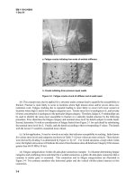
Figure 3-10. Critical areas for miter gates
EM 1110-2-6054
1 Dec 01
4-1
Chapter 4
Detailed Inspection
4-1. Introduction
This chapter summarizes appropriate inspection procedures, nondestructive testing (NDT) inspection methods,
required inspector qualifications, and code acceptance criteria for defects in new weldments.
4-2. Purpose of Inspection
a. If distressed structural members or connections are identified in the periodic inspection or deterioration
in structural performance is assessed from the initial evaluation, then the entire structure should receive a more
detailed inspection. Detailed inspections may also be used as part of a damage-tolerance fracture control plan.
This fracture control concept is based on the fact that presence of cracklike discontinuities in the structural
members or connections does not necessarily mean the end of the service life of the structure. An integrated
approach using scheduled inspections on the flawed members and analysis of fracture/fatigue resistance of the
same members can assure satisfactory structural performance. The cost for repair or replacement of the flawed
members can therefore be balanced against the inspection cost.
b. To develop schedules for inspection when the damage-tolerance fracture control plan is used, fracture
mechanics theories must be applied. The inspection periods can be determined by fatigue propagation analysis
of the cracked structural members. The crack growth history from a detectable size to the critical size can be
predicted using the propagation laws (e.g., Paris's crack growth law). Time interval between inspections should
be a fraction of this crack growth life. The optimum inspection intervals vary with service conditions and the
discontinuity conditions. These inspection intervals should be short enough that the cracks that were not
detectable at the preceding inspections do not have time to propagate to failure before the next scheduled
inspection. A procedure for planning the inspection schedules from the crack growth analysis is presented in
Chapter 6.
4-3. Inspection Procedures
a. Inspection of cracks. Field inspection for cracking on welded or riveted structures can be
accomplished by various NDT methods. The six NDT methods commonly used in industry are visual testing
(VT), penetrant testing (PT), magnetic-particle testing (MT), radiographic testing (RT), ultrasonic testing (UT),
and eddy-current testing (ET). Selection of an NDT method for inspection depends on a number of variables,
including the nature of the discontinuity, accessibility, joint type and geometry, material type, detectability and
reliability of the inspection method, inspector qualifications, and economic considerations. A summary of
NDT methods that describes advantages and disadvantages of each is provided in paragraph 4-5 and Table 4-1.
The following are recommended steps for inspecting for cracks:
(1) Visual examination, particularly with the aid of a magnifying glass (5 H or higher), is the most efficient
first step.
(2) If cracks are suspected and the gate component is dry, PT inspection can be used to confirm the
presence of a crack. For most cases, more sophisticated methods, such as UT and MT, can also be employed
but may not be needed.
(3) Record the location, orientation, and length of the cracks. Record conditions of the gate when cracks
are detected.
EM 1110-2-6054
1 Dec 01
4-2
Table 4-1
Selection Guide for Inspection Method
Method Applications Advantages Disadvantages
Visual Surface discontinuities Economical, fast Limited to visual acuity
of the inspector
Liquid Surface cracks and porosity Relatively inexpensive and Cleaning is needed before and after
penetrant reasonably rapid inspection. Surface films hide
defects
Magnetic Surface discontinuities and Relatively economical and Applicable only to ferromagnetic
particle large subsurface voids expedient materials
Radiographic Voluminous discontinuities Provides a permanent Planar discontinuities must be favorably
Surface and internal record aligned with radiation beam. Cost
discontinuities of equipment is high
Ultrasonic Most discontinuities Sensitive to planar type Small, thick parts may be difficult
discontinuities. High to inspect. Requires a skilled
penetration capability operator.
Eddy current Surface and subsurface Painted or coated surfaces Many variables can affect the test
discontinuities can be inspected. signal
High speed
(4) Take photographs of all cracks showing their position relative to the components of the structure.
(5) The inspector should complete a report following the actual inspection. The report should include the
identification and location of inspected structures, date and time of inspection, type of inspection, inspection
procedure, inspection equipment, inspector identity and qualifications, and a record of discontinuities detected
that includes the location, size, orientation, and classification of each discontinuity. Standard symbols are
found in AWS (1998b).
b. Inspection for loose rivets. The inspection of riveted structures should include procedures to identify
loose and/or deteriorated rivets. Loose rivets may exist where there are corrosion patterns around the rivet
head (as shown in Figure 4-1) or where fretting corrosion (Chapter 2) is observed. A rivet with a deteriorated
head may be loose. If loose rivets are suspected, a nonvisual means of inspection is likely required. A com-
monly practiced nonvisual inspection technique is to impact the rivet head transversely with a hammer. The
effectiveness of the rivet may be judged by the tone of the impact. Ewins (1985) describes a method in which
the rivet is impacted longitudinally with an instrumented impact hammer. A vibration signal is emitted from
the tested rivet. By monitoring the vibration signal emanating from the rivet and comparing the signal to that
of a sound rivet, the condition can be determined. The magnitude of the impact force must be consistent for
these comparisons. Generally, the signal from a loose rivet will have a lower and broader frequency than the
signal from a sound rivet. During inspection, it is not necessary to check each rivet in a structure. Detrimental
situations can be identified by testing a representative sample of rivets.
c. Inspection for corrosion. Appropriate tools to assist in measuring and defining corrosion damage
include a depth micrometer (for pitting), feeler gages (for crevice corrosion), an ultrasonic thickness gage (for
thinning), a ball peen or instrumented hammer (for corroded or loose rivets), a camera, a tape measure, and a
means to collect water samples. When corrosion is observed, the type, extent, severity, and possible cause
should be reported. If the corrosion is severe, the specific locations should be noted and the severity (amount
of thinning, etc.) should be quantitatively determined. Some guidelines on subjective quantification of the
severity of corrosion damage are given by Greimann, Stecker, and Rens (1990). If extensive paint system
failure is evident, the river water should be analyzed for corrosiveness. Weight loss (ASTM D2688) and
electrochemical (ASTM G96) methods can be used to determine the corrosivity of water. Corrosivity of water
can also be determined by correlation with pH and ion concentration levels (Pisigan and Singley 1985).
EM 1110-2-6054
1 Dec 01
4-3
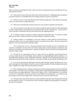
Figure 4-1. Localized corrosion
Although each of these techniques can be used, the weight loss and electrochemical methods are recommended
since they provide a more direct measurement and are easier to apply. Common NDT methods that can be
applied for inspecting structures for corrosion damage include VT inspection and UT inspection. Newer
methods of inspecting for corrosion, such as magnetic resonance testing, are being developed, but these are not
yet ready for routine implementation.
(1) Visual inspection.
(a) Visual inspection is the primary NDT technique of inspecting for corrosion. It can be done in situ,
usually with only ordinary lighting. A visual inspection of all corrosion-susceptible areas (identified in
Chapter 2) should be made to locate, identify, and determine the extent of corrosion. Any failure of the paint
system should also be identified.
(b) The extent of corrosion at crevice sites, particularly in riveted structures, should be recorded during
each inspection. A sheet feeler gauge may be used to quantify the width of a crevice exhibiting corrosion.
Measuring the depth of the crevice (distance into the crevice) may be difficult due to corrosion product
blocking the gauge.
(c) When corrosion exists around rivet heads, deterioration of the rivet head and rivet should be checked.
A deteriorated rivet will have reduced strength and may not perform as intended. Figure 4-2 shows where rivet
heads have split or have developed rosette heads. A corrosion pattern around a rivet may suggest that corrosion
is occurring somewhere beneath the rivet head, or that the rivet is loose. Figure 4-1 shows such a corrosion
pattern. The corrosion pattern should always be recorded in these instances.
(d) The extent of paint system failure and regions of localized discoloration of structural components
should be recorded. In areas where paint failure has occurred, the surface should be visually examined for
pitting. When pitting is present, it should be quantified using a probe type depth gauge following guidance
specified in ASTM G46.
EM 1110-2-6054
1 Dec 01
4-4
Figure 4-2. Corrosion of rivet heads
(2) Ultrasonic inspection.
(a) Ultrasonic inspection is useful when corrosion appears to have caused significant thickness loss in
critical components and can be used to obtain a baseline reference for thickness. The thickness of a steel plate
or part can be determined to an accuracy of ±0.01 cm (0.005 in.). The technique can be performed through a
paint film or through surface corrosion with only a slight loss in accuracy. Ultrasonic transducers are available
in a number of sizes. Thus, ultrasonic inspection is useful in determining both general and localized thickness
loss due to corrosion, even on curved skin plates.
(b) Ultrasonic inspection can be used when only one side of a component is accessible. The open surface
can be scanned with the transducer to identify thickness variation over the surface and to determine where
corrosion has occurred. Methods and equipment for automated scanning and mapping of thickness variation
are available but are probably not economically justifiable for in situ use on hydraulic steel structures.
(c) When ultrasonic inspection is used, the transducer must be coupled to the steel using a coupling liquid,
but this is not a serious limitation. Ultrasonic inspection to determine thickness is generally not reliable when
pitting corrosion is prevalent, because the size and depth of the pitting impair the output signal of the
transducer.
d. Inspection for plastically deformed members. When plastically deformed or buckled members are
found during an inspection, the type and extent of the deformation must be described accurately and in detail
so that an assessment of the effect of the damage can be made. The location of the damaged member should be
noted as well as the type and extent of deformation (global member buckling, local buckling of a flange, or
impact damage to the skin plate). The magnitude of all deformations should be measured and recorded.
Sketches and photographs should be made. The condition of adjacent members, effect on structure
performance or operation, and possible causes of the damage should also be noted.
EM 1110-2-6054
1 Dec 01
4-5
4-4. Inspector Qualifications
For the results of an inspection to be worthwhile, the inspector must be qualified. Corps personnel are often
not adequately trained in inspection methods; therefore, inspections are often performed via contract with
inspection specialists. The following qualification requirements apply to all inspectors, whether Government
or contractor employees.
a. Qualification in NDT methods.
(1) The effectiveness of NDT depends on the capabilities of the person who performs the test. Inspectors
performing NDT should be qualified in accordance with the American Society for Nondestructive Testing
(ASNT) Recommended Practice No. SNT-TC-1A (ASNT 1980). The SNT-TC-1A document is a guide to
establish practices for training, qualification, and certification of NDT personnel. Three basic levels of
qualification are defined in SNT-TC-1A as follows:
(a) NDT Level I: An NDT Level I individual shall be qualified to properly perform specific calibrations,
specific NDT, and specific evaluations for acceptance or rejection determinations according to written
instructions and to record results.
(b) NDT Level II: An NDT Level II individual shall be qualified to set up and calibrate equipment and to
interpret and evaluate results with respect to applicable codes, standards, and specifications. The NDT Level II
individual shall be able to organize and report the results of NDT.
(c) NDT Level III: An NDT Level III individual shall be capable of establishing techniques and
procedures; interpreting codes, standards, and procedures; and designating the particular NDT methods,
techniques, and procedures to be used.
(2) Certification of all levels of NDT personnel is the responsibility of the employer. The employer must
establish a written practice for the control and administration of NDT personnel training, examination, and
certification.
b. Qualification in weld inspection.
(1) Welding inspectors are responsible for judging the quality of the product in relation to some form of
written specification. The following qualifications are necessary for individuals to inspect welds adequately.
(a) A welding inspector must be familiar with engineering drawings and able to interpret specifications.
(b) A welding inspector should be familiar with welding processes and welding procedures.
(c) A welding inspector should be able to maintain adequate records.
(d) A welding inspector should have passed an eye examination with or without corrective lenses to prove
near-vision acuity of Snellen English, or equivalent, at 300 mm (12 in.), and far-vision acuity of 20/40, or
better.
(2) In addition, one of the following three requirements is necessary to qualify an individual as a weld
inspector for a hydraulic steel structure:
(a) Current or previous certification as an AWS Certified Welding Inspector (CWI) in accordance with the
provisions of ANSI/AWS QC1.
EM 1110-2-6054
1 Dec 01
4-7
indications. Some substances in the penetrants can affect structural materials. If penetrants are corrosive to the
material being inspected, they should be avoided.
c. Magnetic particle testing (MT). MT inspection is used to detect surface or near-surface discontinuities
in ferromagnetic materials. ASTM E709 and E1316 and ANSI/AWS B1.10 provide information on MT.
Magnetic fields can be generated by yokes, coils, central conductors, prod contacts, and induced current.
When the material is magnetized, magnetic discontinuities that lie in a direction generally transverse to the
direction of the magnetic field will cause a leakage field at the surface of the material. The presence of this
leakage field is detected when fine ferromagnetic particles are applied over the surface. Some of the particles
are gathered and held by the leakage field. This collection of particles indicates the discontinuities. Several
magnetic particle materials commonly used for MT inspection are dry powders (i.e., suitable for field
inspection of large object), wet magnetic particles suspended in water or light oil (i.e., suitable for very fine or
shallow discontinuities), magnetic slurry suspended in heavy oil, and magnetic particles dispersed in the liquid
polymers to form solid indications.
(1) Advantages. The MT inspection is a sensitive means of detecting small and shallow surface or near-
surface discontinuities in ferromagnetic materials. MT inspection is considerably less expensive than
radiographic or ultrasonic inspection and is generally faster and more economical than penetrant inspection.
Compared to PT inspection, MT inspection has the advantage of revealing cracks filled with foreign material.
(2) Disadvantages and limitations. MT inspection is limited to ferromagnetic material. For good results,
the magnetic field must be in a direction that will intercept the direction of the discontinuity. Large currents
sometimes are required for very large parts. Care is necessary to avoid local heating and burning of surfaces at
the points of electrical contact. Demagnetization is sometimes necessary after inspection. Discontinuities must
be open to the surface or must be in the near subsurface to create flux leakage of sufficient strength to
accumulate magnetic particles. If a discontinuity is oriented parallel to the lines of force, it will be essentially
undetectable.
d. Radiographic testing (RT). RT inspection is based on differential absorption of penetrating radiation
by the material being inspected. Radiation from the source is absorbed by the test piece as the radiation passes
through it. The discontinuity and its surrounding material absorb different amounts of penetrating radiation.
Thus, the amount of radiation that impinges on the film in the area beneath the discontinuity is different from
the amount that impinges in the adjacent area. This produces a latent image on the film. When the film is
developed, the discontinuity can be seen as a shadow of different photographic density from that of the image
of the surrounding material. Evaluation of the radiograph is based on a comparison of these differences in
photographic density. The dark regions represent the more easily penetrated parts (i.e., thin sections and most
types of discontinuities) while the lighter regions represent the more difficult areas to penetrate (i.e., thick
sections). An essential element to the radiographic process is film, a thin transparent plastic base coated with
fine crystals of silver bromide (emulsion). RT inspection shall conform to ASTM E94, ASTM E142, ASTM
E747, and ASTM E1032. Other applicable documents include ASTM E242, ASTM E1316, ASTM E999,
ASTM E1025, ANSI/AWS B1.10, and ANSI/AWS D1.1.
(1) Advantages. RT inspection detects surface and internal discontinuities, is generally not restricted by
the type of material or grain structure, and provides a permanent record for future review.
(2) Disadvantages and limitations. RT presents a potential radiation hazard to personnel, is costly
(radiographic equipment, facilities, and safety programs are expensive), and is relatively time consuming. The
RT method is difficult to conduct during field applications. To provide reliable detection, discontinuities must
be favorably aligned with the radiation beam, and accessibility to both sides of the parts to be inspected is
required.
EM 1110-2-6054
1 Dec 01
4-8
e. Ultrasonic testing (UT). UT inspection is a nondestructive method in which high-frequency sound
waves are used to detect surface and internal discontinuities. The sound waves travel through the materials to
be inspected and are reflected from surfaces, refracted at interfaces between two substances, and diffracted at
edges or around obstacles. The reflected sound waves are detected and analyzed to define the presence and
location of discontinuities. Cracks, laminations, shrinkage cavities, pores, and other discontinuities that act as
metal-gas interfaces can be easily detected. Inclusions and other nonhomogeneous defects in the metal can also
be detected. UT inspection is usually performed with longitudinal waves or shear waves (i.e., angle beam).
Most UT inspections for discontinuities are performed using angle-beam technique. The pulse-echo method
with A-scan is most commonly used for inspection of welds. The most commonly used frequencies are
between 1 and 5 MHz, with sound beams at angles of 0, 45, 60, and 70 degrees. During application of the
method, all surfaces of the part to be examined should be free of weld spatter, dirt, grease, oil, paint, and loose
scale. Applicable guidance documents include ASTM A435/A435M, ASTM A577/A577M, ASTM E114,
ASTM E164, ASTM E214, ASTM E1316, ANSI/AWS B1.10, and ANSI/AWS D1.1.
(1) Advantages. UT provides near-instantaneous indications of discontinuities. It is not hazardous to
personnel, nor does it have adverse effects on materials. The method is very accurate. It has superior
penetrating power allowing the detection of discontinuities deep in the part, is highly sensitive permitting the
detection of small discontinuities, and provides good accuracy in determining the size, position, and shape of
discontinuities.
(2) Disadvantages and limitations. Manual operation and interpretation of results require experienced
technicians. Even with experienced personnel, reference standards are needed for calibrating the equipment
and for characterizing discontinuities. Parts that are rough, irregular in shape, very small, or inhomogeneous
are difficult or impossible to inspect.
f. Eddy-current testing (ET). ET inspection is an electromagnetic method that is based on the principles
of electromagnetic induction. When an alternating current is passed through a coil, eddy current is created in
the material being tested by an alternating magnetic field. The test coil is electronically monitored to detect the
changes of magnetic field caused by the interaction between the eddy currents and the initial field. Any surface
or subsurface discontinuities that appreciably alter the normal flow of eddy currents can be detected by ET
inspection. ASTM E1316 and ANSI/AWS B1.10 provide guidance on the use of ET.
(1) Advantages. Because ET inspection is an electromagnetic induction technique, it does not require
direct contact between probe and the material being tested, so coated materials can be inspected. ET inspection
is adaptable to high-speed inspection.
(2) Disadvantages and limitations. The test material must be an electrical conductor (not a concern for
inspection of hydraulic steel structures). Internal discontinuities that are more than approximately 6 mm
(1/4 in.) from the surface cannot be accurately detected by eddy-current inspection. The method is based on
indirect measurement, and the correlation between the instrument readings and the structural characteristics of
the material being inspected must be carefully established. Since many variables can affect an eddy-current
signal, interpretation of results must be done by experienced personnel.
4-6. Discontinuity Acceptance Criteria for Weldments
a. Discontinuity classification. The common weld discontinuities detected from various NDT methods can
be classified into planar and nonplanar types. Planar type discontinuities include cracks, delaminations or
laminar tearing, and sometimes incomplete joint penetration or incomplete fusion. The nonplanar type
discontinuities are volumetric weld discontinuities, which include porosity, slag or tungsten inclusions, under-
cut, underfill, and overlap. Figure 4-3 shows these common types of weld discontinuities (ANSI/AWS B1.10).
EM 1110-2-6054
1 Dec 01
4-9
Figure 4-3. Weld discontinuities (ANSI/AWS B1.10; copyright permission granted by
American Welding Society)
b. Acceptance criteria. The results obtained from various NDT inspections for new fabrication are
assessed according to the recommended acceptance criteria for weld discontinuities as presented by ANSI/
AWS D1.1. These acceptance criteria as they apply to various NDT inspection results can be summarized in
three perspectives: weld profile, static loading case, and dynamic loading case. Weld profile is a code
compliance for weld quality. Inspection for this code compliance is usually made by visual inspection with the
aid of a weld gauge. The purpose of this code compliance is to provide information on the structural fitness of
the welds. Weld profile noncompliance may be acceptable if an engineering assessment is conducted. The
code acceptance criteria recognize the effect of dynamic loading on the structures as opposed to the statically
loaded case. Planar type discontinuities are not acceptable in either case, and permissible conditions on
nonplanar type discontinuities are specified in the code criteria with smaller allowances for the dynamically
loaded structures. Repair or replacement of structural members or connections that contain unacceptable
discontinuities (i.e., flaws) may be required. These acceptance criteria are obviously applicable to existing
structures with discontinuities as well. To avoid unnecessary repair or replacement, fracture mechanics
analysis may be conducted to reassess these unacceptable discontinuities for new fabrication or existing
structural weldments. A maintenance schedule may be developed in lieu of immediate repair or replacement of
the distressed members or connections using a damage-tolerance fracture control plan (Chapter 6).
EM 1110-2-6054
1 Dec 01
5-1
Chapter 5
Material and Weld Testing
5-1. Purpose of Testing
a. A structural inspection may reveal that certain structural members or connections are weakened due to
some form of distress, but have not failed. With strength less than the design strength, these members and
connections operate with a safety factor lower than that intended in design. The structure could continue to be
operated with this reduced factor of safety, or the load conditions could be adjusted to raise the actual factor of
safety. To determine the appropriate decision, engineering assessments that include fracture and fatigue
analysis should be conducted, as discussed in Chapter 6. Mechanical properties of the structural members and
welds are usually needed in the analysis.
b. For hydraulic steel structures fabricated in recent years, the materials used for the structural members
and welds are usually well documented and can be identified from the design drawings. For older structures,
however, information on mechanical properties of the structural materials or welds may not be readily
available. Mechanical tests of these materials and welds are sometimes required to determine necessary
information for fracture and fatigue analyses. In addition, determination of the chemical composition of
unknown materials may be required.
5-2. Selection of Samples from Existing Structure
Material information that may be required to evaluate a steel structure includes chemical composition, tensile
strength, bend ductility, fillet weld shear strength, hardness, and fracture toughness. The test samples may be
taken from the materials left from original fabrication, removed from existing gate members or connections, or
obtained from weldments made of similar materials with welding procedures similar to those used in the
original fabrication.
5-3. Chemical Analysis
When the chemical composition of an existing structural (steel) material is not available, it may be necessary to
perform a chemical analysis. This is an important initial task in the overall material and weld testing program.
The information from this analysis will provide a basis for characterizing the properties of the unknown
materials. This information can be used to assist in selecting appropriate NDT methods, assessing corrosion
problems, conducting fracture analyses, and assessing material weldability for possible repair. A chemical
analysis for material compositions should be in conformance with ASTM E30 and E350.
5-4. Tension Test
a. Tension tests provide information on the strength and ductility of materials under uniaxial tensile
stress. The pertinent data obtained from a tension test are ultimate tensile strength, yield strength, Young's
modulus, percent elongation, percent reduction of cross-sectional area, and the stress-strain relationship.
b. Transverse tension tests are generally used to determine weld quality during the weld qualification
process. Similar tests could be used for existing structures if the original fabrication practices can be replicated.
The transverse rectangular tension specimens are machined from a butt-welded plate, with the weld crossing in
the midsection of the specimen (AWS B4.0 (AWS 1998a), Figure C-2). Specimens are then tested to failure in
tension with results reflecting the effects of nonhomogeneous weld/metal interface and other weld defects.
When weldment thickness is beyond the capacity of test equipment, the weldment is divided through its
EM 1110-2-6054
1 Dec 01
5-2
thickness into as many specimens as required to cover the full weld thickness. The results of the partial-
thickness specimens are averaged to determine the properties of the full-thickness joint.
c. The base metal and weld metal tests are performed on a tensile testing machine in accordance with the
requirements of ASTM E8. The machine should be calibrated in accordance with ASTM E4. The rate of
straining should be between 0.05 and 0.5 units per unit of gauge length, per minute.
d. Material properties are calculated as follows:
(1) Ultimate tensile strength = maximum load/original cross-sectional area in the gauge length.
(2) Yield strength = load at 0.2 percent offset/original cross-sectional area in the gauge length.
(3) Percent elongation = (final gauge length - original gauge length)/original gauge length × 100.
(4) Reduction of area: Fit the ends of the fractured specimen together and measure the thickness and
width at the minimum cross section. Calculate the reduced area.
e. At least two specimens should be tested for each sample type. The result of the tension test is the
average of the results of the specimens.
5-5. Bend Test
a. In accordance with ASTM E190, bend tests are generally used in the weld qualification process for
new fabrication. Similar tests, however, could be conducted for existing structures if original fabrication
practices can be simulated. Guided bend tests are used to evaluate the ductility and soundness of welded joints
and to detect incomplete fusion, cracking, delamination, effect of bead configuration, and macrodefects of
welded joints. The quality of welds can be evaluated as a function of ductility to resist cracking during
bending. The top and bottom surfaces of a welded plate are designated as the face and root surfaces, respec-
tively. Face bends have the weld face on the tension side of the bent specimen, and the weld root is on the
tension side for root bends. For thick plates, transverse slices are cut from the welded joint, and one of the cut
side surfaces becomes the tension side of the bent specimen. For all types of bend tests, face, root, and side, the
specimen is tested at ambient temperature, and deformation should occur between 1/2 and 2 min.
b. When the plate thickness is less than or equal to 10 mm (3/8 in.), two specimens are tested for face
bend and two specimens are tested for root bend. When the thickness of the plate is greater than 10 mm
(3/8 in.), four specimens are tested for side bend.
c. Transverse side bend test specimens (Figure A-5 of AWS 1998a) are used for plates that are too thick
for face bend or root bend specimen. The weld is perpendicular to the longitudinal axis of the specimen. The
side showing more significant discontinuities should be the tension surface of the specimen.
d. For a transverse face bend specimen (Figure A-6a of AWS 1998a), the weld is perpendicular to the
longitudinal axis of the specimen. The weld face becomes the tension surface of the specimen during bending.
For a transverse root bend specimen (Figure A-6b of AWS 1998a), the weld is perpendicular to the
longitudinal axis of the specimen. The root surface of the weld becomes the tension surface of the specimen
during bending.
e. During the test, the convex surface of the bent specimen should be examined frequently for cracks or
other open defects. If a crack or open defect is present after bending, exceeding a specified size measured in
any direction, the specimen is considered to be failed. Cracks occurring on the corners of the specimen during
EM 1110-2-6054
1 Dec 01
5-3
testing are not considered to fail a specimen unless they exceed a specified size or show evidence of defects
(AWS 1998a).
5-6. Fillet Weld Shear Test
a. The fillet weld shear test is used to determine the shear strength of fillet welds. Fillet weld shear tests
are generally used in the weld qualification process for new fabrication; however, similar tests could be
conducted for existing structures if original fabrication practices can be simulated. The test is performed in
accordance with the requirements of ASTM E8 on a tensile machine. The machine should be calibrated in
accordance with ASTM E4. For longitudinal shear strength, the specimen is prepared in accordance with
Figure E-1 of AWS B4 (AWS 1998a), and for transverse shear strength, the test specimen is prepared in
accordance with Figure E-2 of AWS B4. The specimen is positioned in the testing machine so that the tensile
load is applied parallel to the longitudinal axis of the specimen. The length, average throat dimension, and legs
of each weld should be measured and reported. The welds are sheared under tensile loads and the maximum
tensile loads are reported.
b. Shear strength in pounds per square inch is calculated by dividing the maximum load by the effective
weld throat area (i.e., theoretical throat thickness times total length of fillet weld sheared). At least two
specimens are tested. The result of the shear test is the average of the results of the specimens. A test is
considered invalid if the failure is caused by a base metal defect. The fracture location must also be included
in the report.
5-7. Hardness Test
a. Hardness tests are used to provide generic information on the material properties (primarily toughness
and strength). Hardness measurements provide indications of metallurgical changes caused by welding,
metallurgical variations, and abrupt microstructural discontinuities in weld joints, brittleness, and relative
sensitivity to cracking under structural loads.
b. Specimens for hardness testing include as-welded partial or complete assemblies, weldments from
which the reinforcement has been removed, and weld joint cross sections. For hardness tests of existing
hydraulic steel structures, the weld reinforcement may or may not be removed. When it is removed, a local
area of the reinforcement is ground smooth before testing. For large assemblies, portable hardness testers are
available that can be transported for use in the field. Microhardness testing of welds is usually performed on
ground, polished, or polished and etched transverse cross sections of the weld joints.
c. The most common hardness testing methods include Brinell, Rockwell, and Vickers tests. Selection of
test method depends on hardness or strength of the material, the size of the welded joints, and the type of
information desired. The Brinell, which is appropriate for field evaluations, produces a large indentation suited
for large welds in heavy plates. The Rockwell test produces much smaller indentations than the Brinell test
and is more suited for hardness traverses. The Rockwell hardness test is also suitable for field inspection if a
portable tester is used (see ASTM E110). The Vickers test makes relatively small indentations and is suited for
hardness measurements of the various regions in the weld heat-affected zone and for fine-scale traverses. The
Brinell and Rockwell tests are generally used for hardness measurements of fusion-welded joints in laboratory
or field environments. For each type of hardness test performed, at least five indentations should be made for
each region. The result of the hardness test is the average of the indentations. The hardness values from
different test methods can be correlated through a conversion chart provided by ASTM E140.
d. The Brinell hardness test is performed in accordance with the requirements of ASTM E10. It is an
indentation hardness test using calibrated machines to force a hard ball into the surface of the material and to
EM 1110-2-6054
1 Dec 01
5-4
measure the diameter of the resulting impression after removal of the load. The Brinell hardness number, HB,
is related to the applied load and to the surface area of the permanent impression made by a ball indenter.
e. The Rockwell hardness test is performed in accordance with the requirements of ASTM E18. This test
is an indentation hardness test, in which a diamond spheroconical indenter or hard ball indenter is forced into
the surface of the material in two operations. The Rockwell hardness number, HR, is a number derived from
the net increase in the depth of indentation as the force is increased from a preliminary test force to a total test
force and then returned to the preliminary test force. The higher the number, the harder the material.
f. The Vickers hardness test is performed in accordance with the requirements of ASTM E92. The
Vickers hardness test is an indentation hardness test in which a square based pyramidal diamond indenter with
specified face angles is forced into the surface of the material. The Vickers hardness number is related to the
applied load and the surface area of the permanent impression.
5-8. Fracture Toughness Test
Fracture toughness testing provides a measure of resistance to fracture of a material. Test methods include
Charpy V-notch test (CVN), Plane-Strain Fracture Toughness test (K
Ic
), and Crack-Tip Opening Displacement
(CTOD) test. The CVN test is used to measure the ability of a material to absorb energy. The K
Ic
and CTOD
tests are used to determine resistance to fracture given a specific crack subject to a specific stress level. As
discussed in Chapter 2, the welding process and welding procedure have a significant effect on the fracture
toughness of a welded joint. If possible, fracture toughness test specimens should be selected from a distressed
member or connection, so that the test results are representative of the structure. As an alternative, test samples
may be made using similar materials and welding procedures to those used in the original fabrication. Size and
orientations of the test specimens taken from structure samples should follow the provisions specified in
Figure D-3 of AWS (1998a). Test specimens should not contain metal that has been affected thermally as a
result of cutting, preparation, or welding stops or starts. When an evaluation of the base metal or heat-affected
zone is required, the location of the notch should be specified.
a. Charpy V-notch test.
(1) The CVN test provides information about behavior of metal when subjected to a single application of a
load resulting in multiaxial stresses associated with a notch coupled with high rates of loading. For some
materials and temperatures, impact tests on notched specimens have been found to predict the likelihood of
brittle fracture better than tension tests or other tests used in material specifications.
(2) The specimen preparation and test procedure for the CVN test is described by ASTM E23. When
specified, the surface finish of the V-notch of the Charpy impact specimen is 0.5 µm (20 µin.), or less. The
testing machine is a pendulum type of rigid construction and of capacity more than sufficient to break the
specimen in one blow. The test is performed at various specified temperatures over the range of temperatures
that covers brittle to ductile behavior.
(3) Five specimens should be tested for each test condition, and the amount of energy absorbed by the
specimen at fracture should be recorded. The highest and lowest values are discarded, and the result is taken as
the average of the remaining three specimens tested. If any specimen fails to break, or jams in the machine, the
data of that specimen are not included in the calculation of the average.
(4) In addition to the absorbed energy, other test indicators, such as lateral expansion of the fractured
specimen and appearance of the fractured surfaces, can also be used to characterize the fracture toughness of
the test material. The amount of expansion on each side of each half can be measured using a lateral expansion
gauge. The two broken halves must be measured individually, and the larger value is used.