Inspection, Evaluation and Repair of Steel Structures Part 9 potx
Bạn đang xem bản rút gọn của tài liệu. Xem và tải ngay bản đầy đủ của tài liệu tại đây (649.21 KB, 14 trang )
EM 1110-2-6054
1 Dec 01
CRACK
SUPPORT
BRACKET
Figure 8-5. Cracked miter gate vertical girder tension flange
(3) Repair alternatives. Due to the general configuration and restrained geometry of this connection,
a repair that restores the original intended strength may be difficult to achieve. However, the crack can be
repaired using splice plates on the flange and web. The splice plates could be welded or bolted. A bolted
repair would result in a Category B detail; however, due to the constrained geometry, the effective area
considering the required bolts may be a concern. A welded repair would result in a Category E condition
at the end of the splice plates. (However, with modern welding practices, the condition would be
improved over that of the original connection.) To minimize the effect of the Category E, the splice
plates could be extended into a region of low stress. For either a welded or bolted repair, a hole should be
drilled at the crack tips. Prior to cracking, the condition could have been improved by grinding the weld
profile smooth, or by retrofitting the welds by peening or GTA remelting procedures. A similar
modification was undertaken on an extensive retrofit of the Yellow Mill Pond Bridge in the early 1980s
(Fisher 1984).
c. Cracked girder and bracing members on a vertical lift gate.
(1) Description of condition. Figure 8-6 shows a connection between a vertical diaphragm, diagonal
bracing members, and a main horizontal girder on a vertical lift gate. This type of connection (intersection
of bracing members, diaphragms, and girders) is a very common occurrence on lift gates, miter gates,
tainter gates, and bridges. Flanges of bracing members and the diaphragm were each welded directly to
the girder flange. Cracking occurred completely through each bracing member and through the
diaphragm flange and girder flange (at various locations on this particular structure). The girder is
designed to resist flexural forces imposed by hydrostatic pressure, and under this condition, the down-
stream flange is subject to tension. The bracing members are designed as members of a truss that resists
vertical loads imposed by the gate weight and water pressure. Therefore, the bracing members are
presumably subjected to axial tension or compression. Field measurements have shown that out-of-plane
displacement and rigidity of end connections may also impose flexure in the bracing members
(Commander et al. 1994).
8-11
EM 1110-2-6054
1 Dec 01
CRACK
Figure 8-6. Cracked girder, diaphragm, and bracing in a lift gate
(2) Cause of cracking. The location and orientation of cracks indicate that cracking initiated at weld
terminations and weld intersections. The re-entrant corners between members and the inferior weld
geometry (overlapping welds, transverse to stress and not ground smooth) both create a critical stress
concentration condition for the stress flow through the girder flange, diaphragm flange, and bracing
members. The attachment to the girder tension flange is a Category E, and considering axial behavior of
intersecting members, a Category C, D, or E situation exists depending on the thickness of joined
elements. (With overlapping welds and poor weld profiles, the strength is likely less than that of a
Category E detail.)
(3) Repair alternatives. It is necessary to restore the girder strength and to provide adequate
connections of the intersecting members. To avoid future fractures, the repair details should improve the
original condition if possible. Various alternatives could be used to repair the girder while improving the
original condition:
(a) One alternative would be to drill holes at the ends of each existing crack and to add a bolted
gusset plate as shown in Figure 8-7. The gusset plate would be sized such that the plate and connected
flanges would resist the required forces considering the net area. This alternative would improve the
fatigue strength to Category B; however, due to the number of bolts required and the resulting reduction
in net area, a very large plate would likely be necessary.
(b) A second alternative would be to use a welded gusset plate. A gusset plate could be placed over
the existing flanges and welded to each flange. This would provide a temporary patch; however, the
fatigue strength considering bracing and girder stresses would be Category E (although with proper
welding procedures and no intersecting welds, the situation would be improved over the original
condition).
(c) A better detail is shown in Figure 8-8. This would require removing a specified length of flange
from each of the intersecting members and replacing the flanges with a single gusset plate. All of the
member flanges would be welded to the gusset plate with full-penetration groove welds, and the member
8-12
EM 1110-2-6054
1 Dec 01
Figure 8-7. Bolted repair alternative for cracked lift gate
Figure 8-8. Welded repair alternative for cracked lift gate
webs would be welded to the gusset plate with full-penetration or fillet welds. Web access holes are
required at flange welds and should be prepared in accordance with ANSI/AWS D1.1. The exact
configuration should be determined to avoid intersecting welds. With this approach, the detail would
improve from a Category E to a Category C or B depending on weld profile and weld inspection
requirements (see requirements for groove welded connections in Table 2-1).
8-13
EM 1110-2-6054
1 Dec 01
d. Cracked bridge floor beam connection angle.
(1) Description of condition. Figure 8-9 shows a crack in a connection angle that attaches a floor
beam to one web of a box girder in a USACE tied arch bridge. The crack extends from the upper edge of
the connection angle downward along the fillet of the angle. The cracks were discovered after
approximately 40 years of service. Similar cracks have been found in at least four connections. The
cracks were repaired by drilling a hole at the end of the crack approximately 6 years ago. Recently,
cracking through the hole was observed in at least one location.
CRACK EXTENDED
PAST HOLE
Figure 8-9. Crack in bridge floorbeam connection angle
(2) Cause of cracking. For the purposes of this example, it is assumed that floor beam flexural forces
cause unintended distortion of the connection angle that was not accounted for in the design. The
connection is assumed to be a simple shear connection and was not designed to resist floor beam flexure.
However, the angle actually resists out-of-plane forces due to connection rigidity, and the crack driving
force is apparently due to the floor beam flexure. The prior repair, which consisted of drilling a hole at
the end of the crack, served to arrest the crack temporarily. However, since the out-of-plane displacement
is not restrained and the floor beam flexure still exists, the crack has reinitiated from the hole.
(3) Repair alternatives. To eliminate the cause of cracking, the connection must be modified to
reduce the inherent rigidity (to minimize bending forces) or to increase the rigidity (to minimize the out-
of-plane displacement of the connection angle). Cases similar to this are discussed by Keating (1994) and
Fisher (1984).
(a) Simple connection. One alternative is to alter the floor beam connection detail to reduce the
connection rigidity such that minimal flexure is imposed at the end of the floor beam. This would
eliminate the driving force that causes the out-of-plane distortion of the angle. Although many repair
details could be designed to serve this purpose, one possibility would be to remove rivets at the top of the
angle and to cut away the corresponding length of angle to reduce the angle length. To account for the
lost shear strength, a seat angle could be added at the bottom of the floor beam. This alternative would
8-14
EM 1110-2-6054
1 Dec 01
maintain the required shear strength and would reduce the connection rigidity that causes crack driving
force.
(b) Rigid connection. Another alternative would be to reinforce the connection to prevent the
distortion. This could be done by attaching the top flange of the floor beam to the box girder web using a
tee section with its flanges bolted to the box girder web and its web bolted to the top flange of the floor
beam. The top portion of the existing connection angle would have to be removed to provide room for
the tee flange. Although the displacement of the original connection angle would be controlled, large
flexural forces would develop at the end of the floor beam due to the connection rigidity. This may result
in other problems such as distress of the girder web, since the connection was designed as a simple
connection.
e. Fractured bars on a trashrack.
(1) Description of condition. Figure 8-10 shows a trashrack used at an inlet structure on a dam. The
trashrack is composed of a steel outer frame, two support beams, and several screen bars that span the
frame across the support beams. The bars were attached on the upstream face of the rack with the edges of
the bar welded directly to the support beams and frame with fillet welds. Seventeen out of twenty of the
bars fractured completely as shown in Figure 8-10. In each of the fractured bars, the cracks initiated at the
end of the weld that joins the bar to the supporting member (on the downstream edge of the bar).
F
FRACTURED SCREEN BARS
TYPICAL
FRACTURE
SUPPORT
BEAM
SCREEN BAR
SUPPORT
BEAM
Figure 8-10. Fractured screen bars on dam intake trashrack
(2) Cause of cracking. Design loads consisted of lateral hydrostatic loads that induce flexure in the
bars. The direction of bending in the bar at the welds is such that the design stress is compressive on the
downstream edge of the bar at the crack locations. Therefore, under design assumptions, cracking is not
expected. The cracking is attributed to tensile fatigue stresses caused by out-of-plane distortion of the bars
8-15
EM 1110-2-6054
1 Dec 01
as they are vibrated by passing water. The weld termination and abrupt change in geometry between the
bar and supporting member create a severe stress concentration resulting in a detail with low fatigue
strength. Even with vibration due to passing water, the cracking might not have occurred given
connection details with higher fatigue strength.
(3) Repair alternatives.
(a) The attachment between the screen bars and supporting members creates a severe stress
concentration condition that could be avoided by using a different type of connection. Similar trashracks
have been designed where the supporting members have carefully sized holes through which the screen
bars pass and there is no need for a welded attachment. This eliminates the stress concentration at the
weld, and it is likely that the screen bars would have a significantly longer life. The actual repair for this
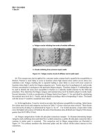
case is shown in Figure 8-11. New screen bar supports with holes (retainer bars) were fabricated and
attached to the existing channel support members with bolts. The bars were then threaded through the
retainer bar holes and held in place by angles at the bar ends oriented perpendicular to the bars and
attached to the existing frame with bolts.
(b) The selected repair eliminated the stress concentration and may have reduced the future number
of load cycles. The fatigue strength has been improved from a detail similar to Category E to Category A.
The repair may also decrease the vibration of the bars with passing water since the new screen bar edges
were rounded on the upstream edge to minimize hydraulic disturbance. Additionally, the overall flexural
stiffness of the bars has been reduced significantly since the bars are now free to rotate at the connection
points. This affects the natural frequency of vibration of the bars and may reduce vibration as water
passes.
f. Crack at diaphragm flange to girder flange intersection in a lift gate.
(1) Description of condition. Figure 8-12 shows a crack in the downstream girder flange of a vertical
lift gate. The crack initiated at the end of the weld between a diaphragm flange and downstream girder
flange and propagated into the girder flange. The fatigue strength of the girder flange at the weld
termination is analogous to Category E. Under typical design assumptions, the girder is in flexure due to
lateral hydrostatic forces and the downstream flange is subject to tensile stress. If cracking were to occur
considering design assumptions, the expected direction of cracking in the girder flange would be
transverse to the flange (perpendicular to flexural tensile stress). However, the crack is oriented at
approximately 45 degrees to the horizontal girder flange.
(2) Cause of cracking. The crack is located at the re-entrant corner between flanges (a severe stress
concentration condition), and tensile cyclic stress exists in the flange at this location. The cracking is
attributed to fatigue cracking of a detail with low fatigue strength. It is also presumed that the condition
was exasperated by out-of-plane distortion of the girder flange. Under vertical hydrostatic loading on the
lift gate, the horizontal girder flanges displace in a vertical plane similar to a uniformly loaded simple
beam as shown in Figure 3-5. The figure illustrates displacement of downstream girder and diaphragm
flanges due to vertical loading. The ends of diaphragm flanges are forced to rotate with the displaced
girder flanges causing out-of-plane flexure in the diaphragm flanges. This induces stresses acting parallel
to the diaphragm flange with tension on one edge and compression on the other as shown in Figure 3-5.
Experimental measurements of lift gate stresses verify this behavior (Commander et al. 1994). At the
point of crack initiation, longitudinal tension stresses exist in both the girder flange (due to lateral
hydrostatic loading) and diaphragm flange (due to out-of-plane distortion). The combined effect of these
perpendicular tensile stresses results in a primary tensile stress that acts perpendicular to the direction of
the existing crack.
8-16
EM 1110-2-6054
1 Dec 01
Figure 8-11. Trashrack repair details (1 in. = 2.54 cm; 1 ft = 0.3 m) (Continued)
8-17
EM 1110-2-6054
1 Dec 01
Figure 8-11. (Concluded)
8-18
EM 1110-2-6054
1 Dec 01
GIRDER FLANGE
DIAPHRAGM
FLANGE
CRACK
Figure 8-12. Cracked girder tension flange at diaphragm of a lift gate
(3) Repair alternatives.
(a) The ideal crack repair would also improve the fatigue strength of the detail and would eliminate
the out-of-plane distortion. However, to eliminate the displacement shown in Figure 3-5 would require
significant structural modification, and the cracking might not have occurred given connection details
with higher fatigue strength. The fatigue strength of the detail would be improved by providing a smooth
radius between the diaphragm flange and girder flange. This would improve the stress concentration
condition and could theoretically improve the fatigue strength from Category E to Category B (see
condition 16 of Table 2-1). The recommended repair is a combination of crack repair procedures shown
in Figures 8-3 and 8-4. First, repair the crack according to Figure 8-4 while following the guidelines for
welded crack repair given in paragraph 8-4a. Then add the radius plate and drill the hole as shown in
Figure 8-3 and as described in paragraph 8-6a(3).
(b) Another possible alternative would be to install a bolted repair similar to that shown in Figure 8-7
(a similar repair is described in paragraph 8-6c(3)). Before the bolted repair is installed, the crack tip
should be drilled and the diaphragm-flange-to-girder-flange weld should be removed to eliminate the
stress concentration.
(c) In the design of new gates, the low fatigue strength details could be eliminated by installing a skin
plate on the downstream face of the gate. This was done in a recent design of a vertical lift gate. Instead
of downstream bracing members, the new design called for a skin plate on the downstream face of the
gate.
g. Crack in vertical lift gate at uncoped web stiffener.
(1) Description of condition. A through-thickness crack that extends through the tension flange of a
built-up girder on a vertical lift gate is shown in Figure 8-13. The structure had been in service for less
than 2 years at the time the crack was discovered. The crack is located where an uncoped transverse web
stiffener is attached. The crack apparently initiated at the intersection of the three welds (web-to-flange,
8-19
EM 1110-2-6054
1 Dec 01
Figure 8-13. Cracked girder tension flange of a lift gate
stiffener-to-web, and stiffener-to-flange). Figure 8-14 shows the intersection of welds where the girder
web, girder flange, and stiffener are joined.
(2) Cause of cracking. The three intersecting welds (web-to-flange, stiffener-to-web, and stiffener-
to-flange) each contract during cooling and contain tensile residual stresses creating a state of triaxial
tension stress. Under the condition of triaxial tensile stress, steel cannot yield and an extremely brittle
condition exists. Additionally, at locations of intersecting welds, there is often a lack of fusion at the end
of one or both stiffener welds. This results in an embedded discontinuity. The fatigue category
considering girder flexure is a Category C for a stiffener coped per American Association of State
Highway and Transportation Officials (AASHTO) requirements (minimum cope dimension is required to
be at least 4 times the thickness of the web). However, the described condition has much lower fatigue
strength due to the increased brittleness and likelihood of embedded discontinuities. The use of uncoped
stiffeners should always be avoided; however, there are many such cases in existing USACE structures. A
similar condition exists in many vertical lift gates and miter gates where built-up girders and diaphragms
intersect. If the diaphragm web is not coped, intersecting welds exist (girder-web-to-girder-flange weld,
diaphragm-web-to-girder-web weld, and the diaphragm- web-to-girder-flange weld).
(3) Repair alternatives. Prior to cracking, a general retrofit for uncoped stiffeners is to drill a hole in
the stiffener adjacent to the intersection and grind all surfaces smooth. The drilled hole removes the weld
intersection and effectively serves as a cope. A similar type repair has been completed on web connection
plates that intersect with transverse web stiffeners (Fisher 1984). The actual repair of this condition
consisted of a bolted splice plate (Figure 8-15). Ideally, the stiffener should have been drilled near the
intersection (as previously described) before the splice plate was installed. Additionally, the crack tip
should have been located and drilled out. With this repair, the crack is isolated and the fatigue strength is
improved to Category B. It is possible that a welded repair (similar to that described in paragraph 8-6a(3)
for a crack that extends into the web), could have been completed. However, such a weld repair would
have been difficult or impossible with the existing stiffener located adjacent to the crack.
8-20
EM 1110-2-6054
1 Dec 01
Figure 8-14. Intersecting welds at web stiffener of the girder shown in Figure 8-13
Figure 8-15. Bolted repair splice for the girder shown in Figure 8-13
h. Cracked handrails.
(1) Description of condition. After less than 2 years of service, severe cracking occurred at
numerous locations on a welded steel handrail (Figure 8-16). The basic railing configuration is shown in
Figure 8-17. All railing consists of 38-mm (1-1/2-in.) stainless steel pipe. The top rails are continuous
and are fillet welded to the top of vertical posts. The bottom rails consist of segments of pipe fillet
welded at each end to the vertical posts. Considering flexure in the rails, the fatigue strength of the rails at
8-21
EM 1110-2-6054
1 Dec 01
FRACTURED RAIL
Figure 8-16. Cracked steel handrail
Figure 8-17. Steel handrail schematic (1 in. = 2.54 cm; 1 ft = 0.3 m)
the post is similar to Category C. Vertical cracks (perpendicular to the rails) located at the outer edges of
the posts occurred in the top and bottom rails at numerous locations. Several of the cracks propagated
through the pipe.
(2) Cause of cracking. Cracking is attributed to high cycle fatigue. A laboratory analysis was con-
ducted on one of the failed pipes to determine the cause of cracking. The analysis showed that the crack
8-22
EM 1110-2-6054
1 Dec 01
initiated at the weld toe and propagated to failure under high cycle vibration loading. Field observations
confirmed that the rails vibrated with significant midspan displacement when subjected to wind loading.
(3) Repair. The handrails were repaired with bolted tee and cross fittings fabricated to fit snugly
around the intersecting pipes (Figure 8-18). The fittings consist of two pieces that sandwich the pipe like
two halves of a sleeve to form a bolted splice. The first repair fittings were aluminum because steel
fittings were not available. Therefore, corrosion was also a consideration since stainless steel and
aluminum are dissimilar metals. To protect the aluminum from corroding, an electric isolater that
consisted of a thick epoxy-based paint was applied to the inside surface of the fittings. After 2 to 3 years,
the aluminum fittings had corroded significantly. The fittings have since been replaced with custom-
manufactured stainless steel fittings. This repair improved the original fatigue strength from Category C
to Category B. In addition, the rails are now more flexible since their end connections are no longer rigid.
This may improve the vibration problem (similar to the discussion of repair of the trashrack bars in
paragraph 8-6e).
Figure 8-18. Bolted tee connection retrofit of fractured hand rail
8-23
EM 1110-2-6054
1 Dec 01
A-1
Appendix A
References
A-1. Required Publications
ER 1110-2-100
Periodic Inspection and Continuing Evaluation of Completed Civil Works Structures
ER 1110-2-1150
Engineering and Design for Civil Works Projects
ER 1110-2-8157
Responsibility for Hydraulic Steel Structures
EM 1110-2-2105
Design of Hydraulic Steel Structures
EM 1110-2-2701
Vertical Lift Gates
EM 1110-2-2702
Design of Spillway Tainter Gates
EM 1110-2-2703
Lock Gates and Operating Equipment
EM 1110-2-3400
Painting: New Construction and Maintenance
CWGS 05036
Metallizing: Hydraulic Structures
CWGS 09940
Painting: Hydraulic Structures
American Association of State Highway and Transportation Officials 1996
American Association of State Highway and Transportation Officials. 1996. “Standard Specifications for
Highway Bridges,” Designation: AASHTO HB-16, 16
th
ed., Washington, DC.
ANSI/AWS B1.10
American National Standards Institute/American Welding Society. “Guide for the Nondestructive Inspection
of Welds,” Designation: ANSI/AWS B1.10-99, Miami, FL.
ANSI/AWS D1.1
American National Standards Institute/American Welding Society. “Structural Welding Code – Steel,”
Designation: ANSI/AWS D1.1-2000, Miami, FL.
ANSI/AWS QC1
American National Standards Institute/American Welding Society. “Standard for AWS Certification of
Welding Inspectors,” Designation: ANSI/AWS QC1-96, Miami, FL.