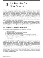
AIR POLLUTION CONTROL EQUIPMENT SELECTION GUIDE - CHAPTER 2 ppt
Bạn đang xem bản rút gọn của tài liệu. Xem và tải ngay bản đầy đủ của tài liệu tại đây (1.15 MB, 8 trang )
© 2002 by CRC Press LLC
chapter 2
Adsorption devices
Device type
Adsorption devices
consist of adsorptive media, either static or mobile, in
a containing vessel through which the gas and its contaminants are
passed. The contaminants are adsorbed onto and into pores in the adsorb-
ing media.
Typical applications and uses
Adsorbers
are most commonly used for solvent recovery, control of hydro-
carbon emissions from storage tanks, transfer facilities, printing operations,
and similar processes where volatile hydrocarbons are present. Activated
carbon types are also used to control sulfurous odor, such as that from
sewage treatment plants. Special impregnated carbons are used to chemically
react with the contaminant once it is adsorbed thereby extending the carbon
life. Where the hydrocarbon has recovery value, adsorbers are often used
after process vents, evaporators, or distillation columns to polish the emis-
sion down to regulatory limits. They are also used on process vents in lieu
of thermal oxidizers.
Regenerative adsorbers are generally not used where the contaminant
is not economically recoverable or the desorption process has a low yield.
For example, cases where adding steam to desorb the carbon results in an
unusable water mixture tends to make adsorption less attractive.
Drum type units are often attached to process tanks to control hydro-
carbon breathing or fill venting losses. The gas flow rates are typically low
and these drum type units can be applied very economically.
Filter type units are used in ventilation systems for hospitals, clean
rooms, auditoriums, bus stations, loading docks, and other environments
where adsorbable hydrocarbons may be present.
© 2002 by CRC Press LLC
Operating principles
Gas adsorption
is the physical capturing of contaminant gas molecules onto
or into the surface of a suitable solid adsorbent, such as activate carbon,
zeolite, diatomaceous earth, clays, or other porous media. The gas molecule
is physically trapped by the pore openings in the media and accumulates
over time until the media saturates and can hold no more. In some devices,
the media is desorbed in place through the application of a gas such as
nitrogen, or steam, to drive the contaminant from the pore openings of the
media. In others, the media itself is directed to a device where thermal energy
(heat) is applied to desorb and recover the media.
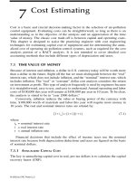
Adsorption is basically a pore surface and size phenomenon. The size
of the gas molecule dictates the pore size of the required adsorbent and the
bulk pore area of the adsorbent per unit volume determines the amount of
adsorbent required to control the specific pollutant. Adsorbents exhibit cer-
tain physical characteristics with respect to pore size. These characteristics
are generally called
macropores
and
micropores
as shown in Figure 2.1. As
defined by the word prefixes,
macro
pores are large pore openings and
micro
pores are small pore openings. In practice, adsorbents exhibit a mixture
of both. The volume of adsorbent required is controlled by the contaminant
Figure 2.1
Macropores and micropores (Barnebey Sutcliffe Corp.).
Area available
to both
adsorbates
and solvent.
Area available
only to
solvent and
smaller
adsorbate.
Area
available
only to
solvent.
© 2002 by CRC Press LLC
gas rate and the amount of time allowed before breakthrough is permitted
to occur. Breakthrough occurs when the pores are effectively filled with the
contaminants or interfering compounds.
The process of activating activated carbon is basically one of opening up
its pores. The carbon can be acid-washed then carefully heated in a reducing
atmosphere or it can be otherwise treated to open the available pores.
Various adsorbents reflect known pore sizes and exhibit specific areas
per unit volume. Application engineers have developed
adsorption isotherms
for various pollutants as they relate to specific adsorbent types. In the family
of activated carbons, for example, there are dozens of different carbon types
(peanut shell-based, coconut shell-based, mineral carbon-based, etc.), each
exemplifying specific pore size and area characteristics. The adsorption iso-
therms are used to predict the rate of capture of that pollutant in the adsor-
bent and to therefore anticipate breakthrough.
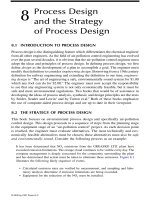
Figure 2.2 shows a typical adsorption isotherm curve. Adsorption tends
to follow the lessons learned earlier about number of transfer units (NTUs)
and driving force. The concentration gradient is important in adsorption
processes because a large gradient tends to fill pores quickly, thereby reduc-
ing the probability of continued adsorption at a high rate. The designer
therefore must allow for a sufficient volume of adsorbent, not only for its
ultimate capacity prior to breakthrough, but also for the concentration gra-
dient that may exist. If the contaminant exists in high concentration, the
volume of adsorbent is increased and the speed at which the gas flows
through the adsorbent is decreased.
Primary mechanisms used
Although the contaminant gas molecule must be fitted to the available pore
size of the adsorbent, the mechanism actually holding the molecule onto the
adsorbent is believed to be van der Waals and other weak attractive forces.
Figure 2.2
Adsorption isotherm (Amcec, Inc.).
40
35
30
25
20
15
10
5
WT %
PPM bv
5,000 10,000
at 75° F
TOLUENE
ETHYL ALCOHOL
ACETONE
TOLUENE
AT 200°F
© 2002 by CRC Press LLC
The adsorption process is more mechanical than chemical. An exception to
the latter is chemically treated adsorbents wherein the pores are precharged
with a chemical that reacts with the contaminant upon contact.
Given that the contaminant molecules are mechanically attached, they
can often be de-attached or desorbed through the application of steam,
heated gases, inert gases, or other processes that force the contaminant out
of the pores. In this manner, the adsorbent can be regenerated and resused
to some extent until the useful life of the adsorbent is reached.
Design basics
Adsorbers
are usually either of the throwaway or regenerative type. The
throwaway type involves the use of a fixed bed of adsorbent in a containing
vessel. These vessels can be either periodically emptied of the adsorbent or
the entire chamber with adsorbent can be exchanged for a new one. The
adsorbent is either regenerated remotely or is thrown way. In the regenera-
tive type, the adsorbent is regenerated or desorbed in place. This typically
involves two chambers that can be isolated. One chamber is actively adsorb-
ing while the other is being desorbed either with steam, hot air, or an inert
gas such as nitrogen.
The ancillary equipment includes dampers to swing the contaminant
gas stream from one chamber to the other, and isolation valves and controls
to administer steam to desorb
in situ
. Some of these designs use an inert gas
such as nitrogen for desorption purposes. The desorbed vapors are often
condensed and collected or are directed to a thermal oxidizer for destruction.
Figure 2.3 shows a multiple chamber adsorber schematic for capture and
recovery of solvent-laden air and regeneration
in situ
using steam.
Sometimes, the designer creates a deep bed of adsorbent and installs it
in a modular housing. These are popular for point of use volatile organic
compound (VOC) control. Equipped with its own fan and pressure drop
monitor, the packaged unit is simple to install and operate. When the adsor-
bent is consumed (breakthrough occurs), the adsorbent housing can be
shipped for regeneration off-site. Figure 2.4 shows a packaged, deep bed
type adsorption unit.
Adsorber gas velocities are usually very low to reduce the pressure drop
of the system. Because the adsorbent particles are close together, their resis-
tance to gas flow is quite high. Gas velocities of 1 to 3 ft/sec or less are
common. The bed depth is dictated by the calculated volume of adsorbent
needed to operate before breakthrough based upon the adsorption iso-
therm(s) for the contaminant(s) to be removed. To avoid channeling of gases,
multiple beds are sometimes used. Each bed may be 1 to 2 feet thick followed
by a vapor space to permit gas redistribution. This low gas velocity means
that adsorbers are generally large devices.
A throwaway type (drum) adsorber is shown in Figure 2.5. The adsor-
bent is precharged in the drum and the drum is designed for off-site regen-
eration or disposal.
© 2002 by CRC Press LLC
Figure 2.3
Regenerative adsorber (Barnebey Sutcliffe Corp.).
Figure 2.4
Packaged adsorption unit (Barnebey Sutcliffe Corp.).
STRIPPED AIR EXHAUST STRIPPED AIR EXHAUST STRIPPED AIR EXHAUST
STEAM
KEY
SOLVENT LADEN AIR
SOLVENT FREE AIR
STEAM
DRYING & COOLING
AIR
RECOVERED
SOLVENT
WATER MIXTURE
ADSORBER ADSORBER ADSORBER
FILTER
DECANTER
TANK
HEATER
DEMISTER
VENT CONDENSER
CONDENSER
PRODUCT COOLER
COOLER
COOLER
DRYING
AIR
RECOVERED SOLVENT
WATER
SOLVENT
LADEN AIR
© 2002 by CRC Press LLC
These designs are often used for tank vent emissions control for
volatile hydrocarbons where the gas flow rate is 50 to 150 acfm. Upon
achieving breakthrough or scheduled replacement, the canister is
removed from service, sealed, and shipped to the supplier for off-site
regeneration or replacement.
Unfortunately, water and water vapor can be adsorbed as well on most
adsorbents (exception: zeolites). The water vapor becomes, in effect, an
unwanted contaminant because it takes away adsorbent area that would be
better used to collect the real contaminant. To reduce water’s effect on the
adsorbent, humid gas streams are sometimes reduced in water vapor content
by first cooling the gas stream to condense water vapor, then reheating the
stream to be well above the water dewpoint. The adsorber housing is then
insulated to prevent the water from cooling and reforming a vapor. In low
humidity applications, the gas stream is sometimes sent through a bed of
gravel or rocks to remove entrained water vapor. Sending the gases through
a strong acid scrubber can also dry the gases so that the adsorption process
is maximized.
The canister type systems often include a bed of gravel or a separate
water trap canister to reduce the carryover of water to the adsorption can-
ister. Others are band heated to keep the gas humidity below the dewpoint.
Sometimes heated air is bled into the system to reduce the gas moisture
content. The most effective method, however, involves cooling the gases to
condense water followed by indirect reheat.
If the contaminant gas easily desorbs and can exceed the lower explosive
limit (LEL), the adsorber vessel must be designed for explosion-proof oper-
ation. The adsorption process is one of concentrating a dilute gaseous stream
so LEL considerations must be taken into account.
The activated carbon type adsorbers are generally used in applica-
tions of less than 150
°
F. For higher temperatures, zeolites are often used.
Figure 2.5
Canister type adsorbers (Carbtrol Corp.).
© 2002 by CRC Press LLC
Zeolites are mineral-based adsorbents that are less affected by water
vapor and temperature. Zeolites have been effectively used in rotating
wheel type devices as shown in Figure 2.6 and as mentioned in Chapter
1. They are used ahead of thermal oxidizers to concentrate the contami-
nants in a dilute gas stream to a point where they can economically be
thermally destroyed. This concentrator type service reduces the size of
the required thermal oxidizer.
Panel type air filters are also available precharged with activated carbon
or other suitable adsorbent. Figure 2.7 shows such a panel filter wherein the
finely divided carbon is mixed with the filter media itself. In other designs,
pelletized carbon fills the space between filter media panels thereby provid-
ing some VOC control. These designs are used in room ventilation systems.
The adsorbent, the filter media, or both can be pretreated with a biocide to
kill bacteria that may also be found in the gas stream. Highly specialized
filters such as these are used to protect military personnel who handle mobile
vehicles such as tanks and personnel carriers from gaseous weaponry and
deadly battlefield smoke particulate.
Operating suggestions
As previously mentioned, water and water vapor should be removed prior
to non-zeolite type adsorbers. If regenerative type adsorbers are contem-
plated, the vendor should be consulted regarding the integration of the
adsorber into the process and a thorough economic analysis be performed.
Figure 2.6
Zeolite type adsorption concentrator (Munters Zeol).
Exhaust to
Atmosphere
Exhaust to
Atmosphere
Process
Fan
Secondary Heat
Exchanger
Primary Heat
Exchanger
Cooling Fan
Oxidizer Fan
Munters Zeol Rotor
Concentrator
Fuel
VOC
Laden
Air
Oxidizer
© 2002 by CRC Press LLC
On many applications, the use of a regenerative type adsorber can provide
significant savings in recovered solvent or chemical.
With the exception of the rotating wheel type adsorber, the capacity of
any adsorber slowly decreases from the moment of initial operation. As the
adsorption gradually moves to the point of breakthrough, the adsorption
efficiency stays relatively constant. For this reason, time or a breakthrough
sensor (hydrocarbon analyzer) must be used to determine breakthrough. If
batch type adsorbers are used, one must carefully monitor the time between
regeneration or replacement, or invest in monitoring equipment that indi-
cates when regeneration or replacement is required.
Figure 2.7
Panel type adsorption filter (Barnebey Sutcliffe Corp.).