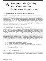
AIR POLLUTION CONTROL EQUIPMENT SELECTION GUIDE - CHAPTER 3 doc
Bạn đang xem bản rút gọn của tài liệu. Xem và tải ngay bản đầy đủ của tài liệu tại đây (926.01 KB, 7 trang )
© 2002 by CRC Press LLC
chapter 3
Biofilters
Device type
Biofilters
use biologic colonies that reside on a supporting substrate (biomass)
and are selected for their ability to produce enzymes that reduce absorbed
organic pollutants to less hazardous or less volatile forms. The biofilter itself
is a combination of adsorber (the media on which the bacteria colonize
provides an adsorption surface) and absorber (the moist biofilm on the media
surface absorbs the contaminants).
Biofilters are considered by some to be green technology, that is, envi-
ronmentally friendly. In reality, the organic chemical action that occurs
within a biofilter is often more complex than that of inorganic chemisorp-
tion systems.
Typical applications and uses
Biofilters
are often used to control the emissions of water-soluble or condens-
able hydrocarbons (such as alcohols), phenols, aldehydes such as formalde-
hyde, odorous mercaptans, organic acids, and similar compounds. They are
used to control emissions from aerosol propellant manufacture and filling
operations, meat processing and packing processes, pharmaceutical manu-
facture (fermenter emissions), and fish and other food processing sources.
Candidate pollutants that can be controlled by biofilters, in general, must
be water soluble because the biodegradation occurs in the moist biofilm layer
supported in the biofilter. Aliphatic hydrocarbons are generally more easily
degraded than aromatic hydrocarbons. Halogenated hydrocarbons show an
increased resistance to this method as their halogen content increases,
although some exceptions exist.
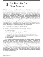
A typical biofilter is shown in cutaway format in Figure 3.1. The basic
components consist of a humidification system to produce a saturated gas
stream (to the lower left), a substrate to support the biomass, a containing
vessel, and some means (such as a fan; upper right) to move the gases
through the biofilter.
© 2002 by CRC Press LLC
Biofilters have also been used to control the emissions of propane and
hexane from the filling of aerosol cans. These systems can actually be built
into the ground, so the containing vessel becomes the surrounding earth.
Buried distribution pipes introduce the contaminated gas beneath the
biomass and its support. The gases percolate and diffuse through the
biomass layer.
Some meat packing facilities ventilate their meat processing devices
(cookers, etc.) into biofilters for odor control. More intense odors are con-
trolled using packed towers, tray towers, fluidized bed scrubbers, and vari-
eties of spray type devices where oxidizing chemicals are used. These devices
can be followed by biofilters, however, wherein the latter act as polishers to
remove residual pollutants.
Operating efficiencies of 70 to 90% are obtainable with a properly
designed unit with higher efficiencies available if extended residence times
are economically feasible. These efficiencies, in the United States at least, are
often less than the levels required by the regulatory authorities; therefore,
biofilters are not as popular here as in other countries.
To be successful, a biofilter must be used under conditions that are
conducive both to the viability of the biofilm and to the absorption of the
contaminant. Typical biofilters are operated under 100
°
F and at 100% relative
humidity. They usually operate using a preconditioning spray chamber or
scrubber to ensure high humidity. Because the resistance to gas flow through
a biofilter is significant, they are often very large devices. Sometimes, an
entire field containing underground distribution pipes is used to provide an
adequately large and stable biomass.
Biofilters are used in applications wherein the gas stream does not con-
tain compounds that are toxic to the bacteria, where the gas stream temper-
ature and humidity can be controlled within a range suitable for sustaining
the bacteria colonies, and where the concentration of pollutants is sufficiently
Figure 3.1
Biofilter (Monsanto Enviro-Chem Systems, Inc.).
© 2002 by CRC Press LLC
low so that the bacteria colony is not overwhelmed. These conditions vary
based on application and bacteria or enzyme selected. Table 3.1 is a list of
popular pollutants that are treatable using biologic methods. This table was
derived from information from Microbac International,
Bioremediation: A
Desk Manual for the Environmental Professional
, by Dennis Schneider and
Robert Billingsley (Cahners Publishing), and from the
Handbook of Bioreme-
diation
, by Robert S. Kerr (ed.), (Lewis Publishers).
Operating principles
Bacteria that produce enzymes suitable for the oxidation or reduction of
the target pollutant are harnessed to do the work in biofilters. They repre-
sent millions of tiny catalytic oxidation sites that in most cases take oxygen
in the gas stream and fix it to the pollutant to mineralize it (convert the
pollutant to CO
2
, water, and innocuous residuals). Some particular bacteria
strains use their enzymes to cleave organic molecules or extract specific
elements (such as sulfur) thereby changing the characteristics of the con-
taminant molecule.
A number of firms have developed specific bacteria strains and/or
enzymes tailored to the control of particular pollutants. If the gas stream can
be conditioned to provide an environment wherein this bacteria strain or its
enzymes can be sustained, the application is a candidate for biofiltration.
Table 3.1
Common Pollutants Recognized as
Biodegradable
Atrazine Heptane
Acetone Hexane
Acrylonitrile Isopropyl acetate
Antracene Isopropyl alcohol
Benzene Lindane
Benzoic acid Methylene chloride
Benzopyrene Methylethyl ketone
Butanol Methylmethacrylate
Butylcellosolve Napthalene
Carbon tetrachloride Nitroglycerine
Chlordane Nonane
Chloroform Octane
Chrysene Pentachlorophenol
p-cresol Phenol
DDT PCB
Dichlorobenzene Pyrene
Dichloroethane Styrene
Dioxane Tetrachlororethylene
Dioxin Trichlorothylene
Dodecane Trinitrotoluene (TNT)
Ethylbenzene Vinyl chloride
Ethyl glycol Xylene
© 2002 by CRC Press LLC
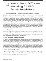
Figure 3.2 shows the basic components of an above-ground biofilter. It
consists of a preconditioning and humidification chamber to raise the gas
relative humidity to 100%, a gas distribution system or header, large vessel
containing a mixture of organic material that both supports the bacteria
colonies and provides food, the bacteria dosing system, and a condensate
return system.
The mixture of organic material the bacteria in the biofilter adhere to is
called
biomass
. This biomass may be cellulose or similar wood-based mate-
rial, peat, carbon (or charcoal), straw, waste organic material, or plastic
material (like scrubber packing) or mixtures thereof designed to support the
bacteria colonies. Generally, a thin wetted layer called a
biofilm
is formed
throughout this media thereby extending the film’s surface area (this is akin
to the use of packing in a packed tower). Because the bacteria usually enjoy
a warm, moist environment, the humidification spray is used to prevent the
biomass from drying out, thereby killing the bacteria. These reactions occur
in a moist environment in the biofilm; therefore, the pollutant must be soluble
in water and be absorbed.
The contaminant gas is absorbed into the moist biofilm and enzymes
secreted by the bacteria reduce or oxidize the contaminant. Given adequate
time, the hydrocarbons are converted to carbon dioxide and water vapor. In
some cases, they are converted to methane gas, much as in a biologic water
treatment system.
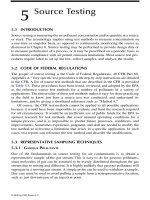
In some biofilters, the specific enzyme has been extracted remotely and
a concentrated solution of that enzyme is used to coat a supporting media
(such as cellulose gauze). The enzyme fixes oxygen in the air to the hydro-
carbon thereby oxidizing it without depletion of the enzyme itself. In this
way, the enzyme is considered to catalyze the oxidation of the contaminant.
Figure 3.3 shows a compact gas cleaning device using an enzyme solution
supported on a gauze type media.
Figure 3.2
Biofilter components (Monsanto Enviro-Chem Systems, Inc.).
Solenoid
Valve
Heat
Addition
Mist
Eliminator
Water
Distributor
Packing
Process
Gas
1
2
3
T
PD
4
6
5
Process
Water
Sump
Recirc. Pump
Bio Media
Load Cell
To Drain
Process Blower
Supplemental
Watering System To Exhaust
Stack
© 2002 by CRC Press LLC
Primary mechanisms used
Absorption is the primary mechanism for the movement of the contami-
nant from the gas phase into the biofilm. Biologic oxidation occurs using
enzymes (called oxygenases). This is the key mechanism for the oxidation
of the contaminant once it is absorbed. Enzymes in the bacteria strain act
as catalysts to fix oxygen to the contaminant, thereby oxidizing the latter.
Some bacteria strains fix other chemicals to the contaminant where a
reducing reaction follows. They basically extract a portion of the contam-
inant, for example sulfur in a mercaptan odor, changing the odorous
compound’s structure.
For long-chain hydrocarbons, a stepwise cleaving process can occur.
Over time, the secreted enzymes break the hydrocarbon chain into smaller
components that eventually result in CO
2
and water. These processes occur
naturally in the environment. In the biofilter, conditions are created and
maintained to make these processes occur more rapidly.
The gases typically mix through diffusion because the gas velocities are
very low (to reduce pressure drop as well). Impaction and interception are
minor in a biofilter given the extremely low vapor velocities at which these
devices operate.
Design basics
In mechanical function, biofilters can be compared to packed towers. The bio-
mass support media is the packing and the biofilm is the absorbing liquid. In
Figure 3.3
CAP™ “Clean Air Plant” compact biofilter (SRE, Inc.).
© 2002 by CRC Press LLC
the case of biofilters, however, the biofilm is stationary. It is attached to the
support media. The gas, therefore, is caused to move slowly through the bio-
mass so that the contaminant gas can diffuse over to the biofilm surface, and
time is allowed for the gas to penetrate the biofilm surface. As a result, gas
velocities are under 1 to 2 ft/sec. Biofilters therefore are usually large devices.
They need not be unsightly, however. Figure 3.4 shows an above-ground
biofilter, the housing of which has been designed for function and appearance.
This design is built in modular components to reduce costs and speed
installation time. The upper vessel is made from fiberglass-reinforced plastic
(FRP) and is sloped to allow for strength and draining of snow and rain. It
sits on a lined concrete basin, which provides structural support and houses
the gas distribution system.
Because the bacteria strains that are used are living organisms, they
require a suitable living environment to survive. This usually results in a
requirement of humidifying and sometimes heating or cooling the gas stream
within a narrow operating window to suit the bacteria strain used. Inlet
relative humidities are usually above 95% and the temperatures are 60 to
110
°
F. Reduced moisture can dry out the biomass and excessive temperatures
can kill the bacteria. The pH is usually 6 to 8, although some bacteria strains
can function at a pH of 4 to as high as 10.
The device also must be designed to be replenished. Access doors must
be provided but adequate pull space must also be provided because biofilters
are often bulk loaded with biomass support material that is dumped into
place and distributed. For this reason, above-ground biofilters often are
configured with driveways next to them allowing for mechanical removal
and replacement of the substrate into dump trucks or other hauling devices.
Operating suggestions
It should be clear from the previous comments that biofilters must be oper-
ated within their thermal and humidity window. Care should be taken to
Figure 3.4
Modular biofilter (Envirogen).
© 2002 by CRC Press LLC
provide a reliable supply of humidification water and supply a suitably
insulated vessel if cold environments are to be encountered.
For hard water, the use of softened water in the humidification system
may be advised to reduce nozzle plugging. If a packed type humidification
device is used, periodic checks should be made regarding the packing con-
dition. The packed zone’s pressure drop should be monitored and the pack-
ing replaced if the pressure drop rises above the vendor’s prescribed figure.
The condensate from the biofilter should be accumulated and, if recycled,
excessively large solids sent through a strainer or filter to prevent nozzle
plugging. If the humidification system is lost, the biofilter can be lost.
It is not uncommon with biofilters to experiment with various bacterial
cultures and substrates. In part, this may reveal the art side of the science.
The reality is that certain bacterial cultures respond to specific pollutants.
When a mixture of pollutants is present, problems can result. Patience is
therefore an asset if one is trying to tackle a multiple pollutant stream.
It is suggested that the temperature of the post-humidification section
and the bed temperature should be monitored. The post-humidification
section should be at the wet bulb temperature or within 2 to 3
°
F thereof.
This indicates near saturation. The bed temperature reflects the bacterial
living conditions. The bacteria culture supplier will have a design range
within which to operate.
Aside from the service accessibility issues and preconditioning require-
ments mentioned previously, the biofilter can be operated as any other absorber.