AIR POLLUTION CONTROL EQUIPMENT SELECTION GUIDE - CHAPTER 7 pptx
Bạn đang xem bản rút gọn của tài liệu. Xem và tải ngay bản đầy đủ của tài liệu tại đây (5.67 MB, 14 trang )
© 2002 by CRC Press LLC
chapter 7
Fabric filter collectors*
Device type
Fabric filter collectors, or baghouses, separate particulate from gas stream
by causing the particulate to pass through a filtering media, a layer of
previously collected (or purposely deposited) particulate, or both. The gas-
borne particulate is intercepted by the fibers of the filtering media, by the
particulate already present on the media surface, or both. To prevent exces-
sive pressure drop as the particulate accumulates, these devices use various
mechanisms to disengage the particulate from the media.
Typical applications and uses
There are three basic dust collector applications. “Nuisance” venting of con-
veyors, transfer points, packing stations and so on — this dust is often sent to
waste. Next is “product collection” venting of classifiers, crushers, storage bins,
air (pneumatic) conveying systems, mills, and flash dryers. This dust is often
recovered because it has value. Last is “process gas filtration” venting of spray
dryers, kilns, power boilers, reactors and so on. The collected solids may or
may not be returned to the process. This dust may or not be worth recovering
but must be controlled for environmental or workplace health reasons.
Fabric filter collectors are also currently used for gas absorption appli-
cations wherein the fabric filter collector is preceded by a spray dryer, dry
Venturi, ductwork injection system, or the bags are precoated with an adsor-
bent or absorbent. Sodium bicarbonate precoat, for example, has been used
to remove gaseous SO
2
from power boiler exhaust gases. A precoat of lime
or a spray dried slurry of lime has also been used on many applications to
simultaneously remove particulate and acidic gases. When toxic dioxins are
present, some applications use activated carbon as part of the precoat.
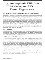
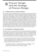
Figure 7.1 shows a baghouse preceded by an evaporative cooler on a
cupola operation. The hot gases enter from the bypass stack at the left and
* This chapter is contributed by Deny Claffey and Michael Claffey, Allied Mechanical, Las Vegas,
Nevada.
© 2002 by CRC Press LLC
proceed to the downward firing cooler/conditioner. An absorbent is injected
in the vertical cylindrical tower at the center of the picture. Toward the right
is the baghouse in which the absorbent and process particulate is collected.
The stack is on the right.
In contrast in size and complexity, the small dust collector in Figure 7.2
collects dust from problem sources and deposits it directly into a drum.
Fabric filter collectors are generally
not
used where the particulate (dust)
is combustible or where the product is to be sent back to the process and
wetted. For the latter, it is often easier to simply use a wet scrubber for
collection. In that manner, the product is prepared to be returned to the
process. Fabric filter collectors are also avoided if glowing embers or other
such damaging carryover exists that could damage the collecting media or
cause a fire. In some cases, a suitably designed cyclone collector is used to
protect the baghouse.
Operating principles
Fabric filter collectors function by filtering or screening particulate from the
gas stream that carries that particulate. To understand this better, first, a little
bit of history.
Dry dust collectors have evolved through the years from very primitive
basic designs to a relatively sophisticated series of machines. Initially, when
air pollution control regulations did not exist, collectors were only required to
catch some of the particulate coming off a process. For example, at one time
Figure 7.1
Baghouse with preconditioner (Bundy Environmental, Inc.).
© 2002 by CRC Press LLC
a drop out box (settling chamber) could in some cases meet the collection
criteria. The dry cyclone was, for a time, the ultimate in collection machinery.
These first dust collectors were simple mechanical machines. The drop
out box (settling chamber) took a moving air stream including dusty partic-
ulate, and slowed it down to a point where the particulate dropped out due
to its own gravity. The slower the air velocity, the heavier the particulate,
and the better the separation. The biggest box allowing for the lowest air
velocity and longest retention time was the best. In the real world, the drop
out box was then and still is well suited to separate lighter floating products
from heavy particulate. The lesson here is that gravity and carrying air
velocity are still very important issues to consider in any dust collector but
they have their limitations.
As mentioned in the dry cyclone
chapter, the dry cyclone uses gravity
and centrifugal force to spin the dust out of the air. Cyclone designs can be
very sophisticated and they can be extremely efficient solids separation
devices and classifiers. Cyclones at one time could separate enough dust
from processes to be considered an air pollution control device. Centrifugal
force alone was not enough. As time went by and air quality standards
became more stringent, a fabric filter collector became the primary device
to use to meet air quality standards. In applications with high particulate
loadings or when processing stringy floating type products, a cyclone makes
an excellent scalper or pre-cleaner for a fabric filter. A cylindrical fabric filter
Figure 7.2
Nuisance dust collector with drum (American Air Filter).
© 2002 by CRC Press LLC
with large annular space between filters and shell set up with a high tan-
gential cyclone type inlet is an excellent heavy duty collector/receiver.
Fabric filters are devices that use some type of permeable fabric to screen
the particulate from moving air. This fabric or material is often called filtering
media or simply, media. The first fabric filters were panel type designs
somewhat like a home hot air furnace filter but their time was short lived
because they could not self-clean. As they plugged or blinded they were
changed manually, discarded, and replaced with new filters. The next step
was to develop a machine with fabric filters that could clean itself. The first
devices used tubular fabric socks arranged in rows in a matrix enclosed in
a housing with a hopper. There were basically two types: the shaker and the
reverse air type. The pulse jet collector followed. All of these devices used
tubular socks of media arranged inside a housing above a hopper to catch
the particulate as it was cleaned off the vertically mounted bags or tubes.
These baghouses incorporate a tube sheet that holds the bag filters in place.
The tube sheet also separates the collector into a clean and dirty side arrange-
ment. The clean air side is called the
clean air plenum
(CAP). The dirty air
side,
dirty air plenum
(DAP). The hopper is located below the DAP, so gravity
helps drop the dust into the hopper. The conventional dust collector is
designed to get rid of the dust in the hopper immediately as it is generated.
A filter receiver type collector has an oversized hopper designed to hold
dust/particulate for some time while the collector is still processing the dirty
air stream.
Primary mechanisms used
Fabric filter collectors primarily use sieving (a combination of impaction and
interception) as the collecting mechanism. The combined porosity of the
media and any previously accumulated particulate serve to produce small
pores through which the new particulate must attempt to pass. This filtering
or sieving action relies on the fact that the net opening at any given time is
smaller than the particulate. Because the particle is bigger than the opening,
it cannot pass through. After collection on the media surface or in the dust
cake, various mechanisms are used to remove the particulate from the media.
After that, the particulate settles by gravity in the device’s housing.
Design basics
The factors that affect sizing and performance of a collector are the material
(dust) itself, the temperature effect on the air, gas, product, fineness of the
material, (fume being an example), dust, and particulate loading in grains
per cubic foot. These factors determine the type of collector selected, the
housing construction required, inlet locations, fabric media selection, and
dust discharge parameters. Dust collector manufacturers distribute applica-
tion data inquiry forms that provide the answers to questions needed to
specify the correct collector design and arrangement for a given application.
© 2002 by CRC Press LLC
For example, it is important to know if the dust is explosive, statically
charged, hygroscopic light, heavy, fine, wet, sticky, and so on. Do we need
insulation, hopper heaters, and special equipment for discharging dust? Is
the collector located inside, outside? Does the exhaust air go back to plant
or outside? These are just a few serious questions meant to indicate just how
important it is for us to know the details before specifying any collector.
After analyzing these parameters, the designer can then choose from
among a wide variety of fabric filter collectors to solve the emissions prob-
lem. The most basic type is the shaker collector, named after its use of a
shaking mechanism to dislodge accumulated particulate.
The shaker collector has tubular socks of a woven media suspended
by a strap on the top of the bag connected to a mechanical shaking arm.
No cages are required to hold the bags open and the lower end of the bag
socks are clamped to the tubesheet located directly above the hopper. The
dirty air enters the unit in the hopper section and is forced to go upward
inside the socks. When the socks get plugged (blinded) the differential
pressure goes up. This creates an electrical signal that shuts off the fan or
closes a damper and shuts off the air flow into the collector. The shaker
mechanism then shakes the filter socks for an adjustable period, dislodging
the dust cake allowing it to fall back down into the hopper. Shakers use a
light woven fabric media designed to be very flexible. After a time, the
shaking stops, the damper opens, air flows through the collector. The
problem with the shaker is that it cannot operate continuously because the
process air and ventilation system must be shut down for it to clean. To
achieve continuous operation, compartmentalized shaker units with some
modules operating cleaning process air and some modules off-line cleaning
filters are required. Also the light-woven, flexible filter media is not par-
ticularly efficient at removing the dust from the air, making the shaker
suspect as an air pollution control device. The shaker is considered a low-
energy intermittent use collector. The filter media does not get worked
very forcefully during cleaning, which can be an asset relative to filter life
in high heat or corrosive applications.
The reverse air collector is built in numerous configurations. It is a
moderate energy device. Generally it uses a caged needled fabric tubular
media making it a pretty good choice for air pollution control applications.
The reverse air cleaning principle is to use an extra air mover for cleaning
filters. This extra air mover produces a higher pressure than the air flowing
through the collector; hence, a flow of air through the cage and media from
the clean side of the filter dislodges the particulate from the dirty side
allowing it to fall into the hopper. The frequency and duration of the cleaning
cycle is much the same as the shaker type. This reverse air flow is usually
better at cleaning than gently shaking the filter bag. The time of the cleaning
cycle is much the same as the shaker. Again this is particularly true when
the collector is set up in modular fashion with some sections of the collector
on line cleaning process air and some sections off line cleaning filters. Clean-
ing the filters off line is easy because there is no process air pressure holding
© 2002 by CRC Press LLC
particulate on the filter bag surface. The only real problem with reverse air
collection is that controlling the air, on and off, during cleaning cycles on
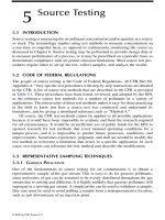
modular arrangements is complex and costly. Figure 7.3 shows an industrial
reverse air collector. The moving arm in the center of the vessel applies a
reverse pulse of air to individual tube rows. Other reverse air collectors break
the housing into compartments using isolation valves. Using blowers, the
air flow through the compartment being cleaned can be reversed, thereby
cleaning the media.
Some reverse air collectors are built with tube sheets low directly above
the hopper with dirty air flowing upward inside uncaged bags and also with
the tubesheet high under the CAP with dirty air flowing to the outside of caged
bags. Reverse air collectors are also built in a cylindrical tall form configuration
as in Figure 7.3. Typically, operating on line, a continuously revolving arm
blowing the higher cleaning air pressure down inside the filters is used as in
our previous example. The solid product falls down between the bags into the
hopper. The round unit with the single revolving cleaning arm is a single
module cleaning a few filters at a time on line making it a stand alone collector.
This is especially true when the reverse air cleaning fan is located within the
Figure 7.3
Reverse air collector (Donaldson Company Inc.).
© 2002 by CRC Press LLC
collector. Some models require an external fan or blower for cleaning energy,
which adds to complexity, cost, space, and moist air cleaning potentials.
An inherent problem with round collectors is they do not use filter space
well. Many, many more filters can be located in a square or rectangular config-
uration. This becomes increasingly important in large installations in the space-
saving sense. Also the tall form, cylindrical design does not lend itself to the
architectural aesthetics’ of the modern low profile industrial park. However, all
and all, the reverse air does excel in some applications especially grain, wood,
paper, and other floating particulate. The cleaning cycle off line is long enough
to free the dust from the filter for an appreciable time so it can drop into the
hopper. The model with a low tubesheet with uncaged filter bags is a good
choice for heavy loadings in hot lime, cement, and kiln processing applications
as the cleaning energy is not too intense to break filters down. Also the mineral
product is heavy enough to drop out of the bags and gravitate to the hopper.
The pulse jet collector is a high energy cleaner as it uses high-pressure
air blown down inside caged filter bags in bursts of 20 to 80 msec. Pulse jets
use filter bags with cages that are suspended from tubesheets between the
DAP and CAP. Needled felt filters are used for hi-cleaning efficiency style,
making it a good air pollution control device. This high pressure air is
typically directed through a Venturi, to increase air volume, raises the air
pressure inside the filter over the process air flowing through the collector
and the shock wave blasts the particulate off the filter bag where it drops
into the hopper. The pulse jet can be round, square, rectangular, short, tall,
very large or very small. It can be modified easily for trough, pyramid
hoppers, high or low inlets, walk-in or trapdoor CAPs allowing for service
in clean air atmosphere. It uses common factory compressed air for cleaning
instead of an extra fan or positive displacement (PD) blower. Some problems
associated with pulse jets are that the high energy imparted to the filter
breaks filter media down, particularly in high heat and or chemical corrosive
atmospheres. Also the location of the Venturi is important with respect to
the tubesheet. With the Venturi located in the filter bag, itself a negative air
pressure exists above the Venturi lip down in the bag area, creating a suction
pressure rather than positive air pressure at the top of the bag during clean-
ing. This leads to buildup of product under the tubesheet. It also takes the
filter area of an 8-ft bag and effectively turns it to that of a 7-ft bag. A Venturi
above the tubesheet eliminates this phenomenon.
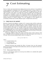
The isometric view of a pulse jet collector is shown in Figure 7.4. In this
unit, the gas inlet plenum is shown to the lower left and the cleaned gas
outlet is at the upper right, as part of a discharge plenum. The cutaway
shows the bags arranged in rows in the collector. The bag access is through
the top of this design. The rectangular sections at the top of the collector are
doors that are removed for bag and Venturi access.
Pulse jet collectors can be configured in a variety of ways. In some cases,
the gas inlet must be located up high. Figure 7.5 is of a pulse jet collector
designed with a high gas entry inlet. It is also equipped with a “walk-in”
type clean air plenum (the chamber located above the Venturis).
© 2002 by CRC Press LLC
Figure 7.4
Pulse jet bag-
house (Bionomic Industries
Inc.).
Figure 7.5
Pulse jet collector with high gas inlet
(Steelcraft, Corp.).
© 2002 by CRC Press LLC
Figure 7.6 shows a similar collector, but equipped with a low level gas
inlet.
Pulse jets have the ability to blast dirty tacky product off the bag. If the
particulate is moderately heavy or in clumps, it will drop into the hopper.
If it is light or floats easily it can get pulled right back onto the bag imme-
diately after the short duration cleaning pulse. Pulse jet self-cleaning cylin-
drical cartridge dust collectors use nominally 6- to 14-inch diameter
×
26-
inch long pleated filters. Typical designs are shown in Figures 7.7 and 7.8.
They were originally thought of as clean air filters because the filter design
and cellulose media type provided very high cleaning efficiency. They were
and still are used to clean ambient air or as final filters (after filters) following
heavy duty conventional fabric filter grade collectors. The pleats provided
much more filter area than a round 4- or 6-inch diameter tubular bag. The
filters less cages were short, easy to handle. The collector holding them could
be compact. Filter service could be done in clean air outside the collector on
the side of the unit. The problem was initially as cartridge units started to
be sold as true front line industrial collectors, the tight pleats would plug
up due to heavy dust loading and blind the filters prematurely. To solve this
problem the perforated metal around the periphery of the filters was
Figure 7.6
Low gas inlet pulse jet collector
(Steelcraft, Corp.).
© 2002 by CRC Press LLC
removed and pleat spacing was opened up so dust could be blown out of
the pleats easier and off the filter. Heavy duty spun bond polyester media
became popular. Filters were made with filter bag geometry allowing for
replacement of round filter bags in other type collectors with pleated filters
(more area) in the 4- to 6-inch diameter range. Currently many styles of self-
cleaning pleated filters are used in industrial processing. They are compact,
service easily, and can tolerate moderate loadings at high levels of cleaning
efficiency. They use compressed air for cleaning energy like pulse jet bag-
houses. Although they are still not the best for heavy loadings and aggressive
dusts, pleated filters continue to gain in the industrial marketplace. The fact
is nothing cleans easier than a smooth, round shape.
There are many types and versions of dust collectors within the various
types. This is because there is a myriad of different applications and certain
designs are best suited for certain applications. In selecting a collector for a
given job it’s critical to understand the details of the process completely. It’s
also critical to understand how the collector works in detail so a match can
be made.
Basically the best dust collector for the job will require the least overall
cleaning energy and cleaning cycles to perform. It will operate at low pres-
sure differential over the filters, holding fan energy down, and will provide
long efficient filter life and infrequent service.
This tells us that when the dirty air enters the collector the dust/partic-
ulate should take the shortest path to the hopper discharge and out. The
Figure 7.7
Cartridge collector (Steelcraft, Corp.).
© 2002 by CRC Press LLC
filters should see only the lighter particulate/dusts that will build up a
permeable filter cake to be cleaned off occasionally.
The prime considerations in collector design are inlet location, and veloc-
ity and direction of dirty air flow inside the collector. For example, if the
inlet is located below the filters, especially in a pyramid or conical hopper
all the air must go upward directly impinging particulate into the filters. As
the air/dust flows up between the filters, the air velocity (rising) increases
carrying the particulate up again and again into the filters. The dust has a
hard time getting down past the inlet blast of air into and out of the hopper.
On the other hand if the dirty air inlet is located near the top of the filters,
the dirty air flow must go downward directly toward the hopper or at worst
horizontally onto the side of the filters. When filters need cleaning the
dust/particulate cake simply drops off into a quiet hopper less any potential
for air pushing it upward back onto the filter media.
Sizing fabric filters starts with an air-to-cloth ratio that field experience
has shown will work on a certain application. The air (cubic feet per
minute) to cloth (media area) calculation gives us the face or
impact velocity
of dirty air as it hits the filter media. Lets assume we have a ventilation
Figure 7.8
Side access cartridge collector (American Air Filter).
© 2002 by CRC Press LLC
process requiring 7200 ACFM and the suggested ratio is 6/1. 7200/6 =
1200 ft. cloth required in the dust collector (nominally). 7200/1200 = 6
CFM/ft
2
or 6 ft/min face velocity. As you can see this provides us with a
relative value for the volume and velocity of dirt and air flowing through
the surface of the media. The higher the gas velocity, the harder it is to
push the dust off because you are pushing the dust back into the on-
coming gas stream.
When using a compartmentalized off-line cleaning system, air-to-cloth
ratio is a much less important factor as no process air is flowing into the
filters. Cleaning off line is very easy at any air-to-cloth ratio.
Let us assume, again, that we are comparing two collectors, both pro-
cessing 7200 CFM. The ratio being considered is nominally 6/1 meaning we
need about 1200 ft
2
of filter media. One collector, the tall unit, needs 60
filters/cages at 6.2-inch diameter
×
12 ft long to get approximately 1200 ft
media. The filters are located on an 8-inch center grid pattern. The housing
in plan is 33.2 ft
2
; the filters in plan, 11.76 ft
2
. The open area between the
filters is 33.2 – 11.76 = 21.44). So, 7200 CFM/21.44 = 336 ft/min velocity. The
other collector, the short one, needs 90 filters/cages
×
8 feet long each. With
all the other parameters and geometry the same, the velocity between filters
is only 233 ft/min. About 30% lower! The tall filter will be cheaper because
it will have fewer filters, cleaning valves, and a smaller housing but the fact
is it will not perform as well as the shorter fatter unit.
One way to determine acceptable can velocity as it relates to air-to-cloth
ratio collector performance is to use an industry rule of thumb for maximum
allowable rising velocity on particulate.
120 ft/min max for up to 10 lb. cu/ft product
240 ft/min max for up to 20 lb. cu/ft product
300 ft/min max for up to 30 lb. cu/ft product
360 ft/min max for up to 50 lb. cu/ft product
400 ft/min max for up to 70 lb. cu/ft product
Using lower velocity is always best. Products that float like ultra fine
light dust, bee’s wings, feathers, and fiberglass fines all need special consid-
eration. Use collectors designed for that service. What we are doing here is
comparing the terminal settling velocity of the dust particle in a relative
sense to the velocity of the air between the filters. Four hundred mesh soft
wood flour at 8 pcf is much harder to drop out in a hopper than 30 mesh
silica sand at 75 pcf. Grain husks, paper trim, and fiber from buffing wheels
act differently than 94 pcf Portland cement. Selecting or specifying a collector
is really a matter of common sense and the experience of the user or man-
ufacturer. In some cases, like dry SO
2
removal we want a coating of soda
bicarbonate on the filters, same goes for pool lime on ultra fine dust or fume.
In these applications, a substantial filter cake provides ultrafiltration. Using
a modular setup with off-line cleaning is a good idea on these continuous
bag coating applications.
© 2002 by CRC Press LLC
Air-to-cloth ratios are only guidelines. Many other factors affect perfor-
mance. For example, the aspect ratio evaluates air-to-cloth ratio as it relates
to dirty air velocities between filters in short or tall form collector. It is a
very important consideration because high velocity in low inlet designs will
not allow dust/particulate to drop down into the hopper.
Operating suggestions
It should be obvious from the previous comments that, to operate a fabric
filter collector efficiently, it must first be sized correctly and then operated
so that the collected dust (particulate) is removed properly. The mechanism
to remove the particulate from the media, and the mechanism to remove the
particulate from the hopper must be kept in good operating condition. If a
shaker type collector is used, the mechanical mechanism to shake the bags
should be inspected and kept properly lubricated. If a reverse air type unit
is used, the reverse air isolation dampers and their actuators should be
periodically inspected and maintained. These dampers and valves are critical
to the reverse air’s proper operation. If a pulse type collector is used in cold
climates, the compressed air supply should be conditioned or dried so that
the fittings and valves do not freeze. The pulse timer (usually electronic)
should be protected from voltage spikes so that its timing circuitry remains
operable.
If the collector is used on a hot source containing acid gases (such as
SO
2
and HCl) and periodically is shut down, the collector should be thor-
oughly insulated and hopper heaters installed as needed. Some collectors
utilize hot air heating systems that recirculate air in the baghouse to uni-
formly distribute the heat. Failure to do so allows the baghouse environment
to pass below the acid dewpoint, which causes localized corrosion and
damage.
For pulse type collectors, various Venturi and cage materials of construc-
tion (MOC) are available. These include coated Venturis, alloy wire cages,
and so on. If the application is corrosive, attention should be paid to the
MOC of the Venturis and cages. If the dust is explosive, special bags with
grounding wires can be installed. Obviously, the grounding system should
be inspected often to make certain that it is operating as intended.
For a hopper discharge problem in which the dust tends to bridge over
the dust outlet, bin activators (shakers) or acoustic horns can often be used
to break up such bridging. Usually, a continuous flow of dust out of the
collector is better than an accumulate and dump type scenario.
On pulse type units, the pulse headers can often be removed from the
top (clean air side) but space must be allowed for their removal. Some
designs allow for the headers to be pulled out laterally. Again, one must
plan ahead for their removal.
If a bag breaks, you usually are in trouble. For that reason, various
vendors offer broken bag detectors that scan the clean air plenum for signs
of particulate. If a broken bag is found, it is not uncommon to replace the
© 2002 by CRC Press LLC
row in which that bag was found as well as the adjacent rows. When one
bag fails, it usually is a sign that others will follow.
To reduce bag injury upon installation, the bag tubesheet holes should
be thoroughly deburred. New bags should be installed vertically (if that was
their original orientation), not on an angle. This prevents the cage from
chaffing the media.
On pulse type units, the bag pulse frequency and duration should be
carefully selected (most vendors have their required settings based upon
experience). The pulse start sequence can often be initiated by a pressure
switch so that a precoat of particulate is allowed to build up first. Every
pulse in some small measure reduces the life of the bag so pulsing should
be done only as needed.
Shaker type collectors often have media tensioning devices that require
initial setup and checking. The collector manufacturer asks that these mea-
sures be followed to get the most use from the media. Unfortunately, these
details are often overlooked.
Fabric filter collectors
provide excellent service when properly applied
to the application and when they are operated as the designer intended.