Kinetics of Materials - R. Balluff S. Allen W. Carter (Wiley 2005) WW Part 13 doc
Bạn đang xem bản rút gọn của tài liệu. Xem và tải ngay bản đầy đủ của tài liệu tại đây (2.67 MB, 40 trang )
466
CHAPTER
19:
NUCLEATION
Therefore, putting these relationships into Eq. 19.12 yields
The lower limit of integration on the right-hand side can be replaced by
oo
without
significant error, and carrying out the integration,
Z,\i
3nN:kT
(19.16)
(1 9.17)
(
19.18)
Equation 19.17 may be interpreted in
a
simple way. If the equilibrium concen-
tration
of critical clusters of size
N,
were present, and if every critical cluster that
grew beyond size
N,
continued to grow without decaying back to
a
smaller size, the
nucleation rate would be equal to
J
=
PcN
exp[-Ag,/(kT)]. However, the actual
concentration of clusters of size
N,
is smaller than the equilibrium concentration,
and many supercritical clusters decay back to smaller sizes. The actual nucleation
rate is therefore smaller and is given by Eq. 19.17, where the first term
(2)
corrects
for
these effects.
This
dimensionless term is often called the
Zeldovich
factor
and
has
a
magnitude typically near 10-l.
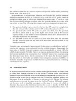
Non-Steady-State Nucleation: The Incubation Time.
Although in principle, non-
steady-state nucleation in single-component systems can be analyzed by solving
the time-dependent nucleation equation (Eq. 19.10) under appropriate initial and
boundary conditions, no exact solutions employing this approach have been
ob-
tained. Instead, various approximate solution have been derived, several of which
have been reviewed by Christian
[3].
Of particular interest is the incubation time
described in Fig. 19.1. During this period, clusters will grow from some initial
distribution, usually essentially free of nuclei, to
a
final steady-state distribution
as
illustrated in Fig. 19.5.
Approximate solutions of the time-dependent nucleation equation discussed by
Christian indicate that the time-dependent nucleation rate in Region I for
a
single-
component system may be approximated by
J(t)
M
Je-t/‘
(
19.19)
where
J
is the final quasi-steady-state rate and
T
is the incubation time [3].
As-
suming that this is the case,
a
reasonably good estimate for the magnitude of
T
may be obtained using
a
physical argument introduced by Russell
[4,
51. Here it is
argued
that the curve of
AGN
vs.
N
is essentially
flat
in the vicinity of
N
=
Nc,
as
illustrated in Fig. 19.6, and that there is
a
range of cluster size,
6,
over which the
change in
A~N
is less than
kT.
Over this range A~N in Eq. 19.10 may be taken
as
constant, and
this
equation then becomes
(19.20)
19.1:
HOMOGENEOUS
NUCLEATION
467
tI
Figure
19.5:
Cluster-size distribution during transient nucleation.
which is of the form of the simple mass diffusion equation when only
a
concentration
gradient is present. In this range, clusters will therefore grow (“move”) in cluster
space by a random-walk process just as during the mass diffusion of particles. Well
away from
N,,
drift arising from the force field of the potential (i.e.,
A~N)
dom-
inates. The transition from predominant random walking to predominant drifting
occurs when the potential deviates from flatness by approximately
kT
on either
side of
N,
(see Fig. 19.6). Because
of
drift, clusters of size
Af
<
(Nc
-
6/2)
have a
high probability
of
shrinking, whereas clusters
of
size
n/
>
(N,
+
6/2)
have
a
high
probability of growing to stable nucleus size. The time required to form significant
numbers
of
nuclei
(i.e.,
the incubation
time)
will therefore
be
approximately the
time required for clusters to random walk the distance
6
in cluster space, provided
that the time required to reach size
Af
<
(Nc
-6/2)
is
shorter than the random-walk
time. Other calculations indicate that this is indeed the case
[3,
61.
By analogy with
the random walk for simple mass diffusion where, according to the one-dimensional
form
of
Eq.
7.35,
(R2)
=
2Dt,
62
2PC
7%-
(19.21)
Figure
19.6:
Variation
of
free
energy
with
size
of
fluctuation
in
the
nucleation
regime.
468
CHAPTER
19:
NUCLEATION
Furthermore, it is shown in Exercise 19.4 that
(
19.22)
and is therefore closely equal to the square of the Zeldovich factor given by Eq. 19.18.
The results above are in reasonably good agreement with other estimates of
r
based
on approximate analytic and numerical solutions of Eq. 19.10
[3,
61.
19.1.2
Classical Theory
of
Nucleation in a Two-Component System without
Strain Energy
Nuclei in two-component systems need not have the same composition as the parent
phase. For example, B-rich
p
particles may precipitate from an A-rich a-phase
matrix. The bulk free-energy change term in Eq. 19.1 is then given by (NIN,)
AG,,
(where the quantity
AGc
is shown in Fig. 17.6) rather than
N(@
-
pa).
The rate
of nucleation of the
p
phase can be determined by using a two-flux analysis where
B
atoms are added to a cluster by a two-step process consisting of a jump of a
B
atom
onto the cluster from a nearest-neighbor matrix site followed by a replacement jump
in the matrix in which a second
B
atom farther out in the matrix jumps into the site
just evacuated by the first
B
atom [6]. The analysis for the steady-state nucleation
rate is similar to that described previously, and the resulting expression for the
rate is similar to Eq. 19.17. However, the
p,
frequency is replaced by an effective
frequency that reduces to the smaller of either the frequency of the matrix+cluster
jumping or the matrix+matrix replacement jumping. (Note that the controlling
rate is always the slower rate in
a
two-step process.) The concentration of
B
atoms
in the vicinity of the nucleus is expected to be close to its average concentration in
the matrix. Further details are given by Russell [6].
19.1.3
Effect
of
Elastic Strain Energy
When clusters form in solids, an elastic-misfit strain energy is generally present
because of volume and/or shape incompatibilities between the cluster and the ma-
trix. This energy must be added to the bulk chemical free energy in the expression
for
AGN.
Since the strain-energy term is always positive,
it
acts, along with the
interfacial energy term, as a barrier to the nucleation. The magnitude of the elastic-
energy term generally depends upon factors such as the cluster shape, the mismatch
between the cluster and the matrix (see below), and whether the interface between
the matrix and cluster is coherent, semicoherent, or incoherent,
as
described in
Section B.6.
The elastic energy of a
p
cluster in an
a
matrix can be calculated by carrying
out the following four-stage process [7]:
Assume the cluster and the matrix to be linearly elastic continua. Cut the
cluster (modeled
as
an elastic inclusion) out
of
the
a
matrix, leaving a cavity
behind, and relax all stresses in both the inclusion and matrix. The inclusion
will then have a generally different shape than the cavity. The homogeneous
strain required to transform the cavity shape to the inclusion shape is called
the
transformation strain,
E:.
19
I
HOMOGENEOUS
NUCLEATION
469
(ii) Apply surface tractions to the inclusion
so
that it fits back into the cavity.
The tractions necessary to accomplish this,
-agnj,
will be those required to
produce the strains
-E$.
(iii) Insert the inclusion back into the cavity and join the inclusion and matrix
along the inclusion/matrix interface in a manner that reproduces the type
of interface (i.e., coherent, semicoherent, or incoherent) that existed initially
between the
p
cluster and the matrix.
(iv) Remove the applied tractions by applying equal and opposite tractions (i.e.,
a$nj).
This step restores the system to its original state. The tractions
ognj
that act on the system at the
a//?
interface will give rise to ‘‘constrained” dis-
placements
w,C,
and thus strains
E:~,
in both the inclusion and the matrix
which can be computed using the strain-displacement relationships of elastic-
ity theory. Corresponding stresses
atj
can then be computed from Hooke’s
law. The final strains and stresses are then
c,Cj
and
atj
in the matrix and
(&,Cj
-
&$)
and
(otj
-
a$)
in the particle. Finally, the elastic energy can be
calculated from a knowledge of these stresses and strains, since for any elastic
body the elastic energy is given by
1/2
sv
aij&ij
dV.
In problems of this type, the quantities that are given are the inclusion shape,
the stress-free transformation strains
E;,
the elastic properties of the two phases,
and the degree of coherence between the inclusion and the matrix. When the
elastic properties of the inclusion and matrix are the same, the system is said
to be
elastically homogeneous.
Otherwise, it is
elastically inhomogeneous.
The
main difficulty is the calculation of the constrained strains,
EC
Having these, the
calculation of the elastic strain energy in the inclusion and matrix is straightforward.
The original reference to such calculations is Eshelby
[7].
An overview is given by
Christian
[3].
Some of the main results are given below for simple shapes such
as
spheres,
discs, and needles which can be derived from a general ellipsoid of revolution by
varying the relative lengths of its semiaxes. Only the limiting cases when the
alp
interfaces are completely coherent or completely incoherent are included. Inclusions
with semicoherent interfaces and interfaces where various patches possess different
degrees of coherence will exhibit intermediate behavior which is much more com-
plicated. Also, results for faceted interfaces are not included. In most cases, the
energy of a faceted cluster can reasonably be approximated by using the result for a
smoothly shaped cluster whose shape best approximates that of the faceted cluster.
Incoherent Clusters.
As described in Section
B.l,
for incoherent interfaces all of
the lattice registry characteristic of the reference structure (usually taken
as
the
crystal structure of the matrix in the case of phase transformations) is absent and
the interface’s core structure consists of all “bad material.” It is generally assumed
that any shear stresses applied across such an interface can then be quickly relaxed
by interface sliding (see Section
16.2) and that such an interface can therefore
sustain only normal stresses. Material inside an enclosed, truly incoherent inclusion
therefore behaves like
a
fluid under hydrostatic pressure. Nabarro used isotropic
elasticity to find the elastic strain energy of an incoherent inclusion as a function
of its shape
[8].
The transformation strain was taken to be purely. dilational, the
particle was assumed incompressible, and the shape was generalized to that of an
470
CHAPTER
19:
NUCLEATION
ellipsoid of revolution with semiaxes
a, a,
c
so
that its shape was given by
x2
y2
z2
-+-+-=I
a2
a2
c2
(19.23)
The shape could therefore be varied between that of a thin disc (c
<<
a)
and that
of a needle
(c
>>
a).
The strain energy (per unit volume of inclusion) is expressed
in the form
(19.24)
where
E
is the dilational transformation strain and
E(c/a)
is a dimensionless shape-
dependent function that has the form sketched in Fig.
19.7.
From this plot, and the
dependence of
AgE
on E(c/a) given in
Eq.
19.24,
it is apparent that the elastic strain
energy of an incoherent particle can be made arbitrarily small
if
the particle
has
the
form of a thin disc. Of course, such a shape would have very large interfacial area
and corresponding interfacial free energy. The preferred shape for the nucleation is
therefore that which minimizes the sum of the strain and interfacial energies.
AsE
=
6pe2
E
-
(2
SDhere
Figure
19.7:
of
aspect ratio
cia.
Elastic strain energy function
E(c/a)
for
an
incoherent ellipsoid inclusion
Coherent Clusters.
As
described in Section
B.6,
for coherent interfaces all of the
coherence (lattice registry) of the reference lattice is retained. For
a
+
p
phase
transformations, the reference lattice is generally taken
as
the a-phase lattice, and
the interface will contain an array of coherency dislocations
as
in Fig.
B.8,
which
accounts for the surrounding stress field.
A
further example showing a spherical
p
cluster enclosed by a coherent interface is illustrated in Fig.
19.8~.
As
long as the
a/@
interface remains coherent during the growth of a
p
cluster, any shear stresses
across it will be unrelaxed, since no interface sliding is possible in complete contrast
to the case of the incoherent interface discussed above.
Eshelby treated systems that are both elastically homogeneous and elastically
isotropic
[7].
Some results for the ellipsoidal inclusion described by
Eq.
19.23
are
given below.
Case
1.
Pure dilational transformation strain with
&Zz
=
E&
=
&T2.
In an elastically homogeneous system, the elastic strain energy per unit vol-
ume of the inclusion
AgE
is independent of inclusion shape and is given by
(19.25)
19.1:
HOMOGENEOUS NUCLEATION
471
(4
Figure
19.8:
Interfacial structure for
(a)
coherent and
(b)
semicoherent interfaces
between matrix phase
Q
and particle phase
0.
The reference structure
is
the crystal lattice.
Only coherency dislocations are present in (a); in (b), anticoherency dislocations relieve the
elastic strain around the particle.
where
v
is Poisson’s ratio and
p
is the shear mod~lus.~ Another feature of this
case is that purely dilational strain centers do not interact elastically,
so
that
the strain fields of preexisting inclusions do not affect the strain energy of new
ones that form. This is sometimes referred to
as
the Bitter-Crum theorem
[9].
Finally, there is the degree of accommodation-this refers to the fraction of
the total elastic strain energy residing in the matrix. For this example, it can
be shown that two-thirds of AgE always resides in the matri~.~
The case of a pure dilational transformation strain in an inhomogeneous elas-
tically isotropic system has been treated by Barnett et al.
[lo].
For this case,
the elastic strain energy does depend on the shape of the inclusion. Results
are shown in Fig.
19.9,
which shows the ratio of Ag,(inhomo) for the inhomo-
geneous problem to Ag,(homo)
for
the homogeneous case, vs.
c/a.
It is seen
that when the inclusion is stiffer than the matrix, Ag,(inhomo) is
a
minimum
01234567
I
cla
+
Needle
-a
8
Disc
SDhere
Figure
9.9:
Effect of elastic inhomogeneity on elastic strain energy of
a
coheren
-
ellipsoidal inclusion of aspect ratio
c/a.
Stress-free transformationstrains are
E:~
=
&rv
=
&Tz.
From
Barnett
et
al.
[lo].
31t is noted that
Eqs.
19.24
and
19.25
do not agree exactly for the case of
a
sphere. Equation
19.25
correctly contains the factor
(1
+
v)/[3(1
-
u)]
%
2/3,
introduced by Eshelby
as
an image term to
make the surface of the matrix traction-free
[7].
4Further discussion of accommodation can be found in Christian’s text, p.
465 [3].
472
CHAPTER
19:
NUCLEATION
for a spherical inclusion and, when the inclusion is less stiff than the matrix,
it
is
a minimum for a disc.
The elastic energy
of
inhomogeneous, anisotropic, ellipsoidal inclusions can be
studied using Eshelby’s
equivalent-inclusion method.
Chang and Allen stud-
ied coherent ellipsoidal inclusions in cubic crystals and determined energy-
minimizing shapes under
a
variety of conditions, including the presence of
applied uniaxial stresses
[
111.
Case
2.
Unequal dilational strains:
€Zx
=
E~)
€TV
=
E~)
and
€Tz
=
E,.
Here
(19.26)
€2
+
EP
+
2V€,EV
-[xc/(32a)][13
(€2
+
E;)
+
2
(16v
-
1)
E,E~
-8
(1
+
2~)
(E~
+
E~)
E~
-
8~21
In this case the second and third terms become vanishingly small for a disc as
it gets very thin, but the first term, which is independent of shape, remains.
In addition, it may be seen that Eq. 19.25 is a special case of Eq. 19.26.
Case
3.
Pure shear transformation strain:
€T3
=
=
512;
all
other
E;
=
0.
Here
np2-u
2c
ASE
=
S-
81-v
a
(
19.27)
Thus, for this case,
AgE becomes vanishingly small for a disc
as
it gets very
thin.
Case
4.
Invariant-plane strain with
€T3
=
&TI
=
S/2,
ET,
=
E~,
and
all
other
An
invariant-plane strain
consists of a simple shear on a plane, plus a normal
strain perpendicular to the plane of shear (see Section 24.1 and Fig. 24.1).
This is a combination of Cases
2
and 3. The expression for Ag, then follows
directly from Eqs. 19.26 and 19.27, with the result that
AgE is proportional
to
cia.
AgE is therefore minimized for a disc-shaped inclusion lying in the
plane of shear.
The term
invariant-plane strain
comes from the fact that the plane
of
shear
in an invariant plane strain is both undistorted and unrotated. Hence the
plane of shear is
a
plane of “exact” matching of the coherent inclusion and
the matrix. In martensitic transformations, this matching is met closely on a
macroscopic but not
a
microscopic scale (see Section 24.3).
€$,
=
0.
Additional factors that should often be considered in the treatment of strain
energies (although commonly ignored) are: elastic anisotropy, which can be consid-
erable, even for cubic crystals; elastic inhomogeneity, which can be treated by the
Eshelby equivalent-inclusion method
[12]
;
nonellipsoidal inclusion shapes; and elas-
tic interactions between inclusions that can be significant, producing, for example,
alignment of adjacent precipitates along elastically soft directions in anisotropic
crystals
[13].
19.1:
HOMOGENEOUS NUCLEATION
473
19.1.4
Both the interfacial energy and any strain energy associated with the formation
of the critical nucleus act
as
barriers to homogeneous nucleation. Both energies
are generally functions of the nucleus shape, and
to
find the nucleus of minimum
energy, it is necessary to find the shape that minimizes the sum of these energies.
As
mentioned above, in the simple case where there is no strain energy, such
as
during
solidification, the shape is given by the Wulff shape (described in Section C.3.1).
However, in solid/solid transformations such
as
precipitation, where strain energy
is generally present, the problem becomes considerably more complex.
The many variables that play
a
role include the anisotropic interfacial energy,
which will be affected by the degree of coherency, and the elastic strain energy
variables, which include the transformation strain, the degree of coherency, and the
elastic properties (including elastic anisotropy).
No
analytical treatments of this
complex minimization problem therefore exist. However,
it
is generally anticipated
that the interfacial energy will be the dominant factor in most cases. Because the
strain energy is proportional to the nucleus volume while the interfacial energy is
proportional to the nucleus area, the interfacial energy should tend to dominate at
the large surface-to-volume ratio characteristic of the small critical nucleus.
Both interfacial energy and strain energy have been incorporated in an analy-
sis that gives some quantitative insight into the role that strain energy may play
in determining the critical nucleus shape [14]. The nucleus is again taken to be
ellipsoidal,
so
that the strain energy can be expressed
as
a
function of
c/a,
as,
for example, in Fig. 19.9. For simplicity, the interfacial energy is assumed to be
isotropic. The free energy to form an ellipsoidal cluster may then be written
Nucleus
Shape
of
Minimum
Energy
where AgB is the bulk free-energy change per unit volume in the transformation,
AgE is a function of
t
where
t
=
c/a,
and
A(<)
is
a shape factor given by
(2t2/4-)
tanh-'
4-
(C
<
1)
i
(25/Jm)
sin-'
4-
(t
>
1)
A(t)
=
2
(t
=
1)
(19.29)
The energy of the critical nucleus
is
now found by minimizing AG with respect
to
a
and
5.
The first minimization produces the results
and
(19.30)
(19.31)
Equation 19.31 may be divided by the expression AG(1)
=
16~~~/[3(Ag~)~], which
is the form Eq. 19.31 would assume if the cluster were a sphere
(5
=
1)
and the
strain energy were zero. Therefore,
(19.32)
474
CHAPTER
19:
NUCLEATION
To find the effect of the strain energy on nucleus shape, the ratio
AG(<)/AG(l)
from Eq.
19.32
is now plotted vs.
<
for various fixed values of the energy ratio
AgE(l)/AgB,
where
AgE(l)
is the strain energy for the spherical nucleus
(E
=
1).
Some results are shown in Fig.
19.10
for a coherent case corresponding to the
lowest curve in Fig.
19.9,
where the elastic energy decreased as the nucleus became
disc-like. The minima in the curves correspond to the critical nuclei of minimum
energy, and the critical nuclei remain spherical until the elastic energy is larger
than about
85%
of the absolute bulk free-energy change.
E
then decreases and
the nucleus becomes progressively more disc-like. Similar results were found for
other cases
[14].
In general, the nucleus shape will not be strongly affected by the
strain energy until
lAgEI
becomes comparable to
IAgBI.
But in most cases,
AG(<)
will be
so
large that no significant homogeneous nucleation is possible. Therefore,
strain energy will not affect the nucleus shape significantly in most actual cases.
However, there will be exceptional cases where the interfacial energy is particularly
small, as in the case of coherent clusters with close lattice matching, where
AG(l),
and therefore
AG(<),
are small enough so that significant nucleation can occur in
the presence of strain energies large enough to affect the nucleus shape.
Lo.50
,
, ,
,
1
"
0.0
0.2
0.4
0.6
0.8
1.0
1.2
1.4
1.6
f-
Figure
19.10:
Free
energy
to form ellipsoidal
nucleus,
Ag((),
as
a
function
of
the
aspect
ratio
(
=
c/a
for various
fixed
values
of the ratio
-Ag,(l)/AgB. Ag(()
is
normalized
by
AG(l),
the value
AG(<)
would assume for
a
spherical nucleus
(6
=
1)
in
the absence of any
strain
energy.
Age(l)
is
the strain energy for a spherical nucleus. The elastic
energy
as
a
function
of
(
corresponds to the lowest
curve
in
Fig.
19.9.
After
Lee
et
al.
[14].
19.1.5
More Complete Expressions for the Classical Nucleation Rate
With the background above, more complete expressions for the classical nucleation
rate can be explored.
Single-Component System with Isotropic Interfaces and
No
Strain Energy.
This rela-
tively simple case could, for example, correspond to the nucleation of
a
pure solid
in a liquid during solidification. For steady-state nucleation, Eq.
19.16
applies with
AG,
given by Eq.
19.4
and it is necessary only to develop an expression for
Pc.
In
a
condensed system, atoms generally must execute a thermally activated jump over a
19.1.
HOMOGENEOUS NUCLEATION
475
local energy barrier in order to join the critical nucleus from the matrix. Therefore,
,&
=
z,Xs
v,
exp[-GF/(kT)]
so
that
(19.33)
Here,
zcXg
is the number of sites in the matrix from which atoms can jump onto
the critical nucleus,
vc
is the effective vibrational frequency for such a jump, and
GT
is the free energy of activation for the jump.
Two-Component System with Isotropic Interfaces and Strain Energy Present.
An ex-
ample of this case is the solid-state precipitation of
a
B-rich
P
phase in an A-rich
a-phase matrix. For steady-state nucleation, Eq. 19.16 again applies. However,
for a generalized ellipsoidal nucleus, the expression for
AG
will have the form of
Eq. 19.28. Also,
P
must be replaced by an effective frequency, as discussed in
Section 19.1.2.
For nuclei that are coherent with the surrounding crystal, the lattice is continuous
across the
cr/P
interface. The jumps controlling the
Pc
frequency factor will then be
essentially matrix-crystal jumps and
Pc
will be equal to the product of the number
of solute atoms surrounding the nucleus in the matrix,
zcXS,
and the solute atom
jump rate,
r,
in the
a
crystal. The jump frequency can reasonably be approximated
by
r
M
*Dl/a2
(see Eq. 7.52, where
*DI
is the solute tracer diffusivity and
a
is the
jump distance). Therefore,
(19.34)
For an incoherent nucleus, the jump rate across the cluster/matrix interface will
be much faster than the lattice jump rate. Therefore, the
pc
frequency factor is
controlled by the lattice-replacement jumping and Eq. 19.34 holds.
In many cases,
AGN
may be affected by the presence of supersaturated lattice
vacancies resulting from the rapid cooling necessary to induce the precipitation.
Incoherent interfaces are generally efficient sources for vacancies (in contrast to the
coherent interfaces considered above), and in cases where
€Zx
is positive, excess
vacancies will annihilate themselves at the cluster/matrix interfaces and therefore
eliminate the elastic strain energy that would otherwise have developed [6].
Fur-
thermore, the excess vacancies may continue to annihilate beyond this point until
the rate of buildup of elastic strain energy due to their annihilation
is
just equal to
the rate at which energy is given up by the vacancy annihilation. In such a case,
the excess vacancies provide a driving force aiding the nucleation and
AGN
takes
the form
AGN
=
flN(Ag~
+
Agv)
+
777fll3
(19.35)
where
SZ
is the atomic volume and
Agv
is the free-energy change due to the vacancy
annihilation. For an elastically homogeneous spherical cluster where the transfor-
mation strain in the absence of any vacancy relaxation would be a uniform dilation,
eTx,
it may be shown (Exercise 19.5) that
where
E
is Young’s modulus. On the other hand, when
€rX
is negative,
Agv
will
be positive and excess vacancies will hinder the nucleation.
476
CHAPTER
19:
NUCLEATION
19.1.6 Nonclassical Models for the Critical Nucleus
When the cluster interface is sufficiently diffuse that it occupies much of the cluster
volume, the classical nucleation model breaks down. This will be the case, for
example, in a precipitation system when the composition is near a spinodal and the
interface becomes diffuse,
as
described in Section 18.2.2. It is then no longer possible
to separate the nucleus energy into volume and interfacial terms, and the nucleus
must be modeled
as
a
single inhomogeneous body. The problem becomes one of
determining the energy of a small critical cluster (nucleus) that is inhomogeneous in
both composition and structure. In the special case when the precipitate and matrix
have the same well-matched structures, the nucleus will be coherent with respect to
a
reference structure that can be taken to be either the matrix or precipitate lattice
and there will be only compositional inhomogeneity with which to contend. The
Cahn-Hilliard gradient-energy continuum approach to the energy of inhomogeneous
systems described in Section 18.2 can then be used [15, 161. When there is a
difference in structure, a discrete atomistic calculation will be required.
An extensive formulation of classical and nonclassical models for homogeneous
nucleation,
as
well
as
experimental tests of their validity, have been carried out for
the Co-Cu precipitation system in which coherent Co-rich nuclei form [15].
19.1.7 Discussion
According to the classical model, the rate of nucleation during precipitation is sen-
sitive to the magnitude of the interfacial energy because the critical nucleus energy,
AG,, varies
as
y3
(Eq.
19.4) and the nucleation rate varies
as
exp[-AG,/(kT)]
(Eq. 19.17). The interfacial energy of incoherent solid/solid interfaces is typicaliy
about 500 mJ m-', whereas that of an interface that is coherent is lower by a factor
of
3
or more. Homogeneous nucleation is therefore expected only in cases where the
nucleus interface is coherent and the interfacial energy is relatively low. Otherwise,
heterogeneous nucleation will predominate. This is consistent with experimental
results obtained by Aaronson and Lee [17].
The nucleation rate is also sensitive to the magnitude of the driving energy
since, according to Eq. 19.4, AG, is proportional to the inverse square of this
quantity. When the temperature is changed and the system becomes metastable,
the driving force increases with continued temperature change until the rate of
nucleation increases explosively,
as
indicated in Fig. 19.11.
It is often useful to estimate values of AG, that may be required to produce an
observable nucleation rate.
For
example, for the nucleation of a solid in a liquid,
Eq. 19.33 applies and reasonable values for the various factors in the equation
exp[-Gy/(kT)]
x
and
J
x
1
~m-~s-'. Therefore, AG,
x
76kT and AG,
must be no larger than approximately 76kT for observable rates of nucleation to
occur.
The explosive onset of nucleation has made the experimental measurement of
nucleation rates difficult,
as
measurable rates can be obtained only under a very
limited range of experimental conditions. An additional difficulty has been counting
the actual number of particles formed, since substantial concurrent particle coars-
ening often occurs (see Fig. 19.1). A common procedure has therefore been to find
the driving force (which is relatively easy to quantify) that is necessary to produce
are: (AG,/~TN,~~T)'/~
x
lo-';
z,Xz
x
10';
v,
x
10
13
s
-1
;
N
1023
cm-3;
19.2:
HETEROGENEOUS NUCLEATION
477
Driving
force
+
Figure
19.11:
Dependence
of
the nucleation rate
J
on the driving force
for
nucleation.
measurable amounts of nucleation and then to look for consistency between the
value of
AG,
obtained from the data and that predicted from theory. Since the
nucleation rate is
so
sensitive to the value of
AG,,
many of the other factors in
the overall expression for the nucleation rate need not be known with high preci-
sion. The various approximations used above to obtain expressions for these factors
therefore do not lead to serious errors.
Despite these difficulties, Aaronson and LeGoues have measured the rate of the
homogeneous nucleation of coherent Co-rich particles in the Co-Cu system by elec-
tron microscopy and compared their results with predictions of both the classical
model and two nonclassical models
[15].
Even though the thickness of the critical
nucleus interface was roughly half the nucleus radius,
as
discussed in Section
23.4.1,
relatively good agreement was obtained between the predictions of all three mod-
els. Furthermore, the predicted absolute nucleation rate was within
a
few orders of
magnitude of the measured rate. This degree of agreement must be considered
as
relatively good in view of the many uncertainties involved.
19.2
H
ET E
RO
G E
N
E
0
US
NU
C
L
EAT
I0
N
Heterogeneous nucleation occurs in competition with homogeneous nucleation. Het-
erogeneous nucleation in solids is favored by the presence of special sites in the
material that are capable of significantly lowering
AG,.
Homogeneous nucleation
is favored by the fact that the number of sites for homogeneous nucleation is gen-
erally equal to the number of atomic sites in the specimen and is therefore
fur
greater than the number of heterogeneous sites. The mechanism with the faster
kinetics dominates. We shall consider two types of heterogeneous nucleation pro-
cesses: nucleation
at
grain boundaries in polycrystalline solids and nucleation on
dislocations.
19.2.1
Grain boundaries are two-dimensional (planar) defects separating three-dimensional
grains. Grain edges are one-dimensional (linear) defects found
at
the intersection
of three grain boundaries. Grain corners are zero-dimensional (point) defects where
four grains touch and where four grain edges meet (see Fig.
15.16).
The number
Nucleation on Grain Boundaries, Grain Edges, and Grain Corners
478
CHAPTER
19:
NUCLEATION
of each type of site per unit volume in a polycrystal decreases
as
its dimensionality
decreases.
Our treatment of nucleation on defects in polycrystalline materials follows that
first developed by Cahn [18]. We employ the simple classical model for the critical
nucleus and assume isotropic interfacial energies. Consider the nucleation of a
@-phase particle on a grain boundary between two grains of an a-phase matrix.
Since
yaa
and
yap
are isotropic, the nucleus will have the shape of two truncated
spheres joined in the plane of the grain boundary (referred to
as
a
lenticular
shape),
as
in Fig. 19.12. (Exercise 19.11 proves this nucleus shape, and Exercise 19.12
treats the related geometry of nucleation on a flat substrate.)
A
circular patch of
grain boundary is eliminated but is replaced by the two spherical cap-shaped
a/@
interfaces. If the energy of this nucleus is lower than that
of
a spherical nucleus
homogeneously nucleated within an a-phase grain, the boundary will act
as
an
effective heterogeneous nucleation site.
The dihedral angle
+
is given by Young’s equation:
yaa
=
2yap cos+ (19.37)
(19.38)
Note the limiting physical situations implied by Eq. 19.38. When
yaa
goes to zero,
the grain boundary loses its ability to catalyze the reaction, and homogeneous
nucleation will be favored
(+
=
7r/2).
When
yaa
rises to
2y@,
the grain boundary
will be a perfect catalyxer of the reaction, because the grain boundary can be
replaced by
a
continuous film of the
,6
phase with no increase in energy
(+
=
0).
In this instance, the nucleation barrier vanishes,
a
situation called
barrierless
nucleation.
The
@
phase is said to
completely wet
the grain boundary when
yaa
2
The nucleation barrier for the lenticular particle shown in Fig. 19.12 can be
274
*
derived using the geometric relations for its volume
V
and interfacial area
A:
2n~3
v=-
3 (2-3cos++cos3+)
and
The semithickness
c
and radius r of the particle are given by
A
=
4rR2
(1
-
cos
+)
(19.39)
(19.40)
r
=
Rsin+ (19.41)
lnterphase
boundary
Figure
19.12:
situated on
a
grain boundary in phase
a.
Geometrical parameters defining size and shape
of
a lenticular
p
particle
19.2
HETEROGENEOUS NUCLEATION
479
and
C=
R(~-cos$)
(19.42)
The free-energy change AGE for nucleation on a boundary site can then be
expressed as
(19.43)
Note that in deriving Eq. 19.43, the quantity
yaa
has been eliminated, using
Eq. 19.37.
It
should be apparent from Eq. 19.43 that the value of the critical
radius R, for heterogeneous nucleation on
a
grain boundary is equal to that for
homogeneous nucleation under the same conditions. The term in square brackets
in Eq. 19.43 is equal to one-half the free-energy change for homogeneous nucleation.
So the ratio of the critical free-energy change
AGF
for boundary nucleation to that
for homogeneous nucleation
AG,"
is
(19.44)
This ratio is the same as that of the volume of the grain boundary particle to that
of a sphere having the same radius of curvature. The dihedral angle
1c,
is the sole
parameter in determining this ratio.
Relations similar to Eq. 19.44 can be derived for the nucleation barrier for grain
edges and corners, AGf and As:, respectively
[18].
The extent to which the
heterogeneous. sites are favored relative to homogeneous nucleation and to each
other can be seen by plotting the ratios AG,"/AG,", AGflAG,", and
AG:/AG,"
vs. cosq, as shown in Fig. 19.13.
0
0.5
1
1.5
2
Figure
19.13:
Ratio of critical free-energy change for heterogeneous nucleation on grain
boundaries, ed es, and corners,
Ag,,
to that for homogeneous nucleation,
AG,",
HS
a
function
of dihedral anae
$.
From
Cahn
[lS].
Figure 19.13 demonstrates that for a given value of
q,
AG, decreases as the
dimensionality of the heterogeneous site decreases. However, the number
of
sites
available for nucleation also decreases
as
the dimensionality decreases. Thus, the
kinetic equations for nucleation theory must be used to predict which mechanism
will dominate. To accomplish this, some assumptions about the polycrystalline
microstructure must be made. Let:
L
=
average grain diameter
15
=
grain boundary thickness
480
CHAPTER
19:
NUCLEATION
n
=
number of atoms per unit volume
nB
=
n(6/L)
=
number of boundary sites per unit volume
nE
=
n(6/L)2
=
number
of
edge sites per unit volume
nc
=
n(6/L)3
=
number of corner sites per unit volume
The densities of the heterogeneous sites can then be approximated by
We now compare the rate of boundary nucleation to the rate of homogeneous nu-
cleation, using Eq. 19.17:
The ratio
of
these rates is
Thus,
Defining
Rg
=
kTln(L/6), the rates
JB
and
JH
are equal when
Rg
=
kT
In
(5)
=
AGF
-
AG,"
(19.45)
(19.46)
(19.47)
(19.48)
(19.49)
and the homogeneous nucleation rate
is
higher when
Rg
>
AG,"
-
AG,".
Similar
analyses yield conditions for which each type of heterogeneous nucleation will be
dominant, with the results summarized in Table 19.1.
Table
19.1:
Boundaries, Edges, and Corners
Conditions
for
Heterogeneous Nucleation at Grain
Dominant Mode Conditions
Homogeneous nucleation
Boundary nucleation
Edge nucleation
Corner nucleation
RB
>
AG,"
-
AG,"
As,"
-
AG,"
>
RB
>
AG,"
-
AG,"
AGE
-
AG,"
>
RB
>
AG,"
-
A@
As,"
-
A62
>
RB
The results can bc prcsented graphically,
as
in
Fig.
19.14.
The
plot shows the
kinetically dominant type
of
nucleation
as
a function of grain size (via
RE),
AGE,
and
r**/r"P.
By setting the nucleation rate,
J,
at
a
fixed value, a curve such
as
abcde
can be plotted to indicate, for given value of
L/6,
the dominant modes of
nucleation at the designated nucleation rate
at
various values of
r*"/r*P.
19
2
HETEROGENEOUS NUCLEATION
481
Homogeneous
0.3
3i
0
0.5
1
1.5“
2
yaa/yap
=
2
cos
l/l
Figure
19.14:
Re imes in which grain corner, edge. boundary, and homogeneous
nucleation are predictecf
to
be dominant.
From
Cahn
[18].
19.2.2
Nucleation on Dislocations
Dislocations in crystals have an excess line energy per unit length that is associated
with the elastic strain field of the dislocation and the bad material in its core. In
many cases, the formation of a particle of the new phase at the dislocation can
reduce this energy, enabling it to act
as
a favorable site for heterogeneous nucleation.
The original treatment of heterogeneous incoherent nucleation on dislocations was
by Cahn [19]. The general topic, including coherent nucleation on dislocations, has
been reviewed by
Larch6
[20].
Incoherent Nucleation.
Consider first incoherent nucleation on dislocations
[
191.
For linearly elastic isotropic materials, the energy per unit length
El
inside a cylin-
der of radius
T
having a dislocation at its center is given by
and
EL
=
-I.(&)
Pb2
(screw dislocation)
4n
Pb2
(edge dislocation)
47~
(1
-
v)
In
(k)
El
=
(19.50)
(19.51)
where
b
is the Burgers vector and
R,
is the usual effective core radius.
Poisson’s ratio
v
is approximately
0.3
for many solids,
so
to a fair approximation,
the energy difference between edge and screw dislocations can be ignored. Following
Cahn.
El=-ln(&)
Bb
2
(19.52)
where
B
x
pbl(2n).
Allowing the entire region inside a radius
T
to transform to incoherent
@
will allow
essentially all of the dislocation energy originally inside the transformed region to
be “released.” Thus, the dislocation catalyzes incoherent nucleation by eliminating
some of the dislocation’s total energy. It is important to note that the dislocation
will still effectively exist in the material along with its strain energy outside the
transformed region, even though the incoherent
@
has replaced the core region. For
example, a Burgers circuit around the dislocation in the matrix material surround-
ing the incoherent @-phase cylinder will still have a closure failure equal to
b.
On
482
CHAPTER
19:
NUCLEATION
forming the incoherent cylinder of radius
r,
the total free energy change per unit
length is
(terms independent of
r)
(19.53)
Bb
2
AG’(r) =m2Ag~+2.1rry-
-lnr+
Extreme values of
AG’(r)
are given by the condition
Bb
br
2r
=
2./r(rAg~
+
7)
-
-
=
0
8
AG‘
(r )
(19.54)
Plotting
AG’(r)
vs.
r
in Fig.
19.15,
two types of behavior are evident, depending
on the value of the parameter,
a,
where
(19.55)
For
a
>
1,
nucleation
is
barrierless-i.e., the transformation is controlled solely by
growth kinetics. However, for
a
c
1,
a
barrier exists. The local minimum of
AG’(r)
at point
A
in the plot corresponds to a metastable cylinder of
p
of radius
ro
forming
along the dislocation line. (In
a
sense, this is analogous to the Cottrell atmosphere
described in Section
3.5.2.)
In Eq.
19.54,
the metastable cylinder’s radius
is
(19.56)
The nucleation barrier for
a
c
1
is then related to the difference in
AG’(r)
between the states
A
and
B
in Fig.
19.15,
where the radius
rc
corresponding to the
unstable state
at
B
is given from Eq.
19.54
as
(19.57)
However, the dislocation is practically infinitely long compared to the size of any
realistic critical nucleus.
If
the nucleus were of uniform radius along a long length
of the dislocation,
AGc
would be very large.
A
critical nucleus will form from
a
local
fluctuation in the form of
a
“bulge” of the cylinder associated with the metastable
state
A,
as
illustrated in Fig.
19.16.
The problem is thus to find the particular
bulged-out shape that corresponds to a
minimum
activation barrier for nucleation.
tl
B
r0
rc
r
Fi
ure
19.16:
cyfndrical precipitate along the core
of
a
dislocation.
From
Cahn
[lQ].
Possible free energy vs. size behavior
for
the formation of
an
incoherent
19
2.
HETEROGENEOUS NUCLEATION
483
Figure
19.16:
dislocation.
Possible shape
for incoherent critical nucleus forming along the core of
a
Let the function
r(t)
specify the shape of the nucleus. The energy to go from
the metastable state
A
to the unstable state
B
(see Fig. 19.15) can be expressed
AG
=
[AG'
(r)
-
AG'
(TO)]
dt
(19.58)
J
From earlier equations,
7rAgB(r2-Tz)
-"I.(:)
2
+2ry
[r/q-rO]}
dt
(19.59)
The unknown shape
r(
t)
is determined by minimizing
AG
using variational calcu-
lus techniques. The solution to the Euler equation
for
this problem is somewhat
complicated, requiring some substitutions and lengthy algebra [19].
From
the re-
sulting equations, one can plot the ratio of the activation barrier for nucleation
on dislocations
AGp
to that for homogeneous nucleation
As:
vs.
a,
in
a
manner
analogous to the plot given in Fig. 19.13, which compared nucleation on various
sites in polycrystals. The resulting plot in Fig. 19.17 shows
a
dramatic decrease in
the relative value
of
AGf
as
cy
-,
1.
Cahn also considered briefly the nucleation kinetics and showed that for reason-
able values of the parameters in the theory, nucleation on dislocations in solids can
be copious [19]. Typically, this occurs when
a
is in the range 0.4-0.7.
"
0
0.2
0.4
0.6
0.8
1.0
a
Figure
19.17:
at dislocations with increasing values
of
the parameter
a
(see
Eq.
19.55).
From
Cahn
[19].
Lowering of the activation barrier for heterogeneous incoherent nucleation
484
CHAPTER
19.
NUCLEATION
Coherent Nucleation.
The elastic interaction between the strain field of the nucleus
and the stress field in the matrix due to the dislocation provides the main catalyzing
force for heterogeneous nucleation of coherent precipitates on dislocations. This
elastic interaction is absent for incoherent precipitates.
For
coherent particles with dilational strains, there is a strong interaction with
the elastic stress field of edge dislocations
[20].
If a particle has a positive dilational
transformation strain
(&
+
E&,
+
&FZ
>
0),
it can relieve some
of
the dislocation’s
strain energy by forming in the region near the core that is under tensile strain.
Conversely, when this strain is negative, the particle will form on the compressive
side. Interactions with screw dislocations are generally considerably weaker, but
can be important for transformation strains with a large shear component. Deter-
minations of the various strain energies use Eshelby’s method of calculating these
quantities
[20].
Bibliography
1.
F.K. LeGoues, H.I. Aaronson, Y.W. Lee, and G.J. Fix. Influence of crystallography
upon critical nucleus shapes and kinetics of homogeneous f.c.c f.c.c. nucleation. I. The
classical theory regime. In
International Conference on Solid-Solid Phase Transfor-
mations,
pages 427-431, Warrendale, PA, 1982. The Minerals, Metals and Materials
Society.
2. D.T. Wu. Nucleation theory.
Solid State Phys.,
50:37-187, 1997.
3. J.W. Christian.
The Theory
of
Transformations
in
Metals and Alloys.
Pergamon
4. K.C. Russell. Linked flux analysis of nucleation in condensed phases.
Acta Metall.,
5. K.C. Russell. Grain boundary nucleation kinetics.
Acta Metall.,
17(8):1123-1131,
6. K.C. Russell. Nucleation in solids: The induction and steady-state effects.
Adv.
7. J.D. Eshelby. On the determination of the elastic field of an ellipsoidal inclusion, and
8.
F.R.N. Nabarro. The influence of elastic strain on the shape of particles segregating
9.
F.
Bitter. On impurities in metals.
Phys. Rev.,
37(11):1527-1547, 1931.
10.
D.M. Barnett, J.K. Lee, H.I. Aaronson, and K.C. Russell. The strain energy
of
coherent ellipsoidal precipitates.
Scnpta Metall.,
8(12):1447-1450, 1974.
11.
S.M.
Allen and J.C. Chang. Elastic energy changes accompanying the gamma-prime
rafting in nickel-base superalloys.
J.
Mater. Res.,
6(9):1843-1855, 1991.
12. J.D. Eshelby. Elastic inclusions and inhomogeneities. In I.N. Sneddon and R. Hill,
editors,
Progress
in
Solid Mechanics,
volume 2, pages 89-140, Amsterdam, 1961.
Nort h-Holland.
13. A.J. Ardell and R.B. Nicholson. On the modulated structure of aged Ni-A1.
Acta
Metall.,
14(10):1295-1310, 1966.
14.
J.K. Lee,
D.M.
Barnett, and H.I. Aaronson. The elastic strain energy of coherent
ellipsoidal precipitates in anisotropic crystalline solids.
Metall. Trans. A,
8(6):963-
970, 1977.
15. H.I. Aaronson and F.K. LeGoues. An assessment of studies on homogeneous diffusional
nucleation kinetics in binary metallic alloys.
Metall. Tk-ans. A,
23(7):1915-1945, 1992.
Press, Oxford, 1975.
16( 5):761-769, 1968.
1969.
Colloid Interface Sci.,
13(3-4):205-318, 1980.
related problems.
Proc. Roy. SOC. A,
241(1226):376-396, 1957.
in an alloy.
Proc. Phys. SOC.,
52(1):90-104, 1940.
EXERCISES
485
16.
17.
18.
19.
20.
J.W. Cahn and J.E. Hilliard. F'ree energy of
a
non-uniform system-111. Nucleation
in
a
two-component incompressible fluid.
J.
Chem. Phys.,
31(3):688-699, 1959.
H.I. Aaronson and J.K. Lee. The Kinetic Equations
of
Solid-rSolid
Nucleation The-
ory
and Comparisons with Experimental Observations, pages
165-229.
The Minerals,
Metals and Materials Society, Warrendale, PA, 2nd edition,
1999.
J.W. Cahn.
Acta Metall.,
4(5):449459, 1956.
J.W. Cahn. Nucleation on dislocations. Acta Metall.,
5(3):16+172, 1957.
F.C.
Larch& Nucleation and precipitation on dislocations. In F.R.N. Nabarro, editor,
Dislocations in
Solids,
volume
4,
pages
137-152,
Amsterdam,
1979.
North-Holland.
The kinetics of grain boundary nucleated reactions.
EXE
RClS
ES
19.1
An equilibrium temperaturecomposition diagram
for
an
A-B
alloy is shown
in Fig.
19.18a.
A nucleation study is carried out
at
800
K
using an alloy
of
30
at.
%
B.
The alloy is initially homogenized
at
1200
K,
then quenched to
800
K
where the steady-state homogeneous nucleation rate is determined to
be
10'
m-3
s-'.
Since
this
rate is
so
small
as
to be barely detectable, it is
desired to change the alloy composition (i-e., increase the supersaturation)
so
that with the same heat treatment the nucleation rate is increased to
1021
m-3
s-l.
Estimate the new alloy composition required to achieve this
at
800
K.
Use the free energy
vs.
composition curves in Fig.
19.18b,
and
assume that the interphase boundary energy per unit area,
7,
is
75
mJ m-2.
List important assumptions in your analysis.
-
3
1200
-
f
ElOOO-
c"
800-
v
-
B
I
I1
I
I1
I
Ill
0 0.2 0.4
0.6 0.8
1
0 0.2
0.4
0.6
0.8
1
Atomic
fraction
B
(4
Atomic
fraction
B
(b)
Figure
19.18:
AgB,
vs.
atomic fraction of component
B
at
T
=
800
K.
(a)
Equilibrium diagram for
A-B
alloy.
(b)
Plot
of
free-energy density,
Solution.
Important assumptions include that the interfacial free energy is isotropic,
that elastic strain energy
is
unimportant, and that the nucleation rates mentioned are for
steady-state nucleation.
The
critical barrier to nucleation,
Ap,,
can be calculated for
the
0.3
atomic fraction
B
alloy using the
tangent-to-curve
construction on the curves
in Fig.
19.18b
to provide the value
AgB
=
-9
x
10'
Jm-3
for the chemical driving
force for this supersaturation at
800
K.
AgC
is given for a spherical critical nucleus by
486
CHAPTER
19:
NUCLEATION
Note that at this temperature,
kT
=
1.38
x
x
800
=
1.10
x
lo-",
50
that
at 800
K
and
XB
=
0.3, AG,
%
79kT.
Based on the criterion that
for
significant
nucleation
AG,
5
76kT
(Section
19.1.7),
it
is reasonable that the nucleation rate is
"barely detectable" in the alloy with
XB
=
0.3.
The steady-state nucleation rate will be proportional to
exp[-AG,/(kT)]
50
we
know
that at 800
K
and
XB
=
0.3,
lo6
=
~'exp(-79) (19.61)
where the constant
C'
is
equal to
NP.2
in the classical theory
for
steady-state nucleation.
We need to find the critical nucleation barrier necessary to achieve the nucleation rate
of
10".
and this will be
or
1
o6
exp( -79)
loz1
exp[ -AG,/(
kT)]
-=
or
-34.54+79=
-
AGc
kT
In
10-l~
=
-79
+
-
kT
(19.62)
(19.63)
and thus
for
the higher nucleation rate
we
must have
AG,
*:
44.5kT
=
4.91
x
lO-"J.
Next, solve for the chemical driving force required to
get
AG,
down to this value, as
follows:
Finally,
use
the free-energy density vs. composition curves and work the tangent-to-
curve construction in reverse. Using the result that
AgB
=
-12
x
107Jm-3,
the
corresponding tangent to the a-phase curve will be at about
33
at.
%
B.
This calculation serves as a good example of the high sensitivity of nucleation rate to
the degree of supersaturation.
19.2
The data below are typical for
a
metal solid solution that can precipitate
a
phase
0
from
a
matrix phase
a.
Assume that the structures of both phases are
such that
0
could
form by coherent homogeneous nucleation
or,
alternatively,
by incoherent homogeneous nucleation. Also, assume that strain energy can
be neglected during incoherent nucleation but must be taken into account
during coherent nucleation. Using the data below, answer the following:
(a)
Below what temperature does
incoherent
nucleation become
thenody-
(b)
Below what temperature does
coherent
nucleation become
thenody-
(c)
Which type
of
nucleation, coherent or incoherent, do you expect to occur
Data
namically possible?
namically possible?
at 510
K?
Justify your answer.
-yc
=
160 mJ m-2
7'
=
800
mJ m-2
AgE
=
2.6
x
lo9
J
m-3
AgB
=
8
x
lo6
(T
-
900K)
J
m
-3
K-'
(coherent interface)
(incoherent interface)
(coherent particle)
(driving force for precipitation)
Solution.
(a) Nucleation becomes thermodynamically possible
if
the thermodynamic driving
For sufficiently large volumes nuclt
force for the transformation is negative.
EXERCISES
487
ated incoherently in the absence of strain energy, and where the interfacial energy
has become unimportant, the total energy change will be negative
if
AgB
<
0.
Therefore, we need
AgB
=
8
x
lo6
(T
-
900
K)
J
m-3
K-’
<
0,
or
T
<
900
K.
(b) For coherent nucleation to be thermodynamically possible,
AgB
+
AgE
<
0.
Therefore, we need
8
x
lo6
(T
-
900
K)
+
2.6
x
lo9
<
0,
or
T
<
575
K.
(c) Assuming that the number of available sites for nucleation is the same for both
coherent and incoherent mechanisms, the nucleation mechanism one expects to
observe will be determined by the critical free-energy barrier,
AG,.
Because the
nucleation rates are proportional to
exp[-AG,/(kT)],
the mechanism with the
lowest value of
AG,
will dominate and be observable
if
AG,
5
76kT,
approxi-
mately.
Assuming spherical nuclei,
A&
=
167ry3/[3(Ags
+
Ag,)’],
where
(19.65)
y
=
yi,
AgE
=
0
y
=
yc,
AgE
#
0
(incoherent nucleation)
(coherent nucleation)
Using the given data, at
T
=
510K, AgB
=
-3.12
x
lo9
Jm-3.
With this,
AGc
=
8.81
x
lO-”J
(incoherent nucleation)
(19.66)
(
AG,
=
2.54
x
lO-”J
(coherent nucleation)
and, similarly,
AGC/(76kT)
=
1.65
>
1
AGC/(76kT)
=
0.475
<
1
(incoherent nucleation)
(coherent nucleation)
(19.67)
Consequently,
coherent
nucleation is expected.
19.3
Martensitic transformations involve a shape deformation that
is
an invariant-
plane strain (simple shear plus a strain normal to the plane of shear). The
elastic coherency-strain energy associated with the shape change is often min-
imized if the martensite forms
as
thin plates lying in the plane of shear. Such a
morphology can be approximated by an oblate spheroid with semiaxes
(r,
r,
c),
with T
>>
c.
The volume
V
and surface area
S
for an oblate spheroid are given
by the relations
(19.68)
V
=
-r
c
and
S
=
2rr2
47r
2
3
The coherency strain energy per unit volume transformed is
Ac
ASE
=
1-
(19.69)
(a)
Find expressions for the size and shape parameters for a coherent critical
nucleus of martensite. Use the data below to calculate values for these
parameters.
(b)
Find the expression for the activation barrier for the formation of a
coherent critical nucleus of martensite. Use the data below to calculate
the value of this quantity.
(c)
Comment on the likelihood of coherent nucleation of martensite under
these conditions.
488
CHAPTER
19:
NUCLEATION
(d)
Make
a
sketch of the free-energy surface
AG(r,
c)
and indicate the loca-
tion of the critical nucleus configuration
(T~,
c,)
on the surface.
Data
AgB
=
-170 MJ m-3
y
=
150 mJ m-'
A
=
2.4
x
lo3
MJ m-3
(chemical driving force at observed transformation
temperature)
(interphase boundary energy per unit area)
(strain energy proportionality factor)
Solution.
(a) Write the
free
energy to form
a
nucleus in the usual way as the sum of
a
bulk
free-energy term, a strain-energy term, and an interfacial-energy term
so
that
(
19.70)
Now
AG
=
AG(c,
T)
and the critical values of
c
and
T
are then found by applying
the simultaneous conditions
4
4
3
3
AG
=
-TT'CA~B
+
-TTC~A
+
2~r'r
Substituting Eq. 19.70 into Eqs. 19.71 and solving for
rC
and cc yields
(19.71)
(19.72)
Using the data provided, these quantities evaluate to
(19.73)
C
T
rC
=
50nm cc
=
1.5nm
-
=
0.035
(b)
Substituting Eqs. 19.72 into Eq. 19.70 then yields
32~ A2y3
AgC
=
-~
(AgB)4
Using the data provided, this quantity
is
equal to
AG,
=
7.8
x
J
(19.74)
(19.75)
(c) Nucleation would proceed at observable rates
if
A&
5
76kT. Assuming
a
nucle-
ation temperature of
350
K,
=
1.6
x
105
(19.76)
7.8
x
J
-
A
Gc
kT
1.38
x
J
K-l
x
350K
which
is
huge compared to 76!
So
homogeneous nucleation would be very unlikely.
Note that the size parameter
rC
is
particularly large and thus the critical nucleus
volume
is
large, consistent with the large value of
A&.
(d) The saddle point on the free-energy surface,
(rC,cc),
is
indicated in Fig. 19.19.
EXERCISES
489
Figure
19.19:
Saddle
point
on
free-energy surface.
19.4
Derive
Eq.
19.22;
i.e.,
1
1
a2A(7~
-= (w)
62
8kT
N=Nc
Solution.
Approximate the curve of
AGN
vs.
n/
in Fig.
19.6
by a circle of radius
R.
Then
kT
=
R
-
(19.77)
Expanding Eq.
19.77
and neglecting the higher-order terms,
1
11
P-mz
The standard expression for the curvature,
1/R,
is
(19.78)
(19.79)
Combining Eqs.
19.78
and
19.79,
the desired result is then obtained.
19.5
Derive
Eq.
19.36
for
the free-energy change due to the annihilation
of
excess
vacancies
at
nucleating incoherent clusters during precipitation.
Hint:
The chemical potential
of
excess vacancies is given by
Eq.
3.66.
Solution.
First, calculate the energy change contributed by the excess vacancies which
are eliminated to relieve the strain due to the dilatation
$1.
If
V
is the cluster volume,
AV
=
3€TIV.
The number of vacancies required is then
N
=
3ETlV/n
and the
free-energy change due to the removal of these vacancies is therefore
(19.80)
Next,
calculate the free-energy change due to the destruction
of
the additional vacancies
which are removed to the point where the rate of buildup of elastic strain due to
their annihilation is just equal
to
the rate at which energy is given up by the vacancy
annihilation.
If
N
vacancies are destroyed in this fashion, the volume of matrix removed
490
CHAPTER
19:
NUCLEATION
is
Nn
and the dilational strain that
is
induced is then
Nn/3V.
Using
Eq.
19.25,
the
strain energy that is created is
(19.81)
The energy released
by
the annihilated vacancies is
As;
=
NkTln(Xv/XGq),
and the
total energy change is then
(19.82)
AG"
is minimized when
aAG"/aN
=
0,
and carrying out this operation, the minimum
value
is
(19.83)
Adding
Eqs.
19.80
and
19.83,
the total energy change (per unit cluster volume) is then
finally
2
(19.84)
3zn 9(1
-
Y)
Ag
=
kTln
n
19.6
Figure
19.20
shows
a
cross section through the center of
a
critical nucleus
that has cylindrical symmetry around the vertical
axis
EF.
AB
and
CD
are
the traces of
flat
facets that possess the interfacial energy (per unit area)
yf,
and AC and
BD
are the traces of the spherical portion of the interface that
possesses the corresponding energy
y.
E
/
F
Figure
19.20:
Critical nucleus shape.
(a)
Construct
a
Wulff plot that is consistent with the critical nucleus shape
(b)
Show that the free energy to form this critical nucleus can be written
(Wulff shape) in Fig.
19.20.
1
AQ,(sphere)
2
A&
=
-
(3
cos
a
-
coS3
a)
(19.85)
where Ag,(sphere) is the free energy to form
a
critical nucleus for the
same transformation but which is spherical and possesses the interfacial
energy
y.
Assume the classical model for the nucleus.